2010 NISSAN TIIDA valve
[x] Cancel search: valvePage 313 of 3745

AT-296
< SERVICE INFORMATION >
REPAIR FOR COMPONENT PARTS
DISASSEMBLY
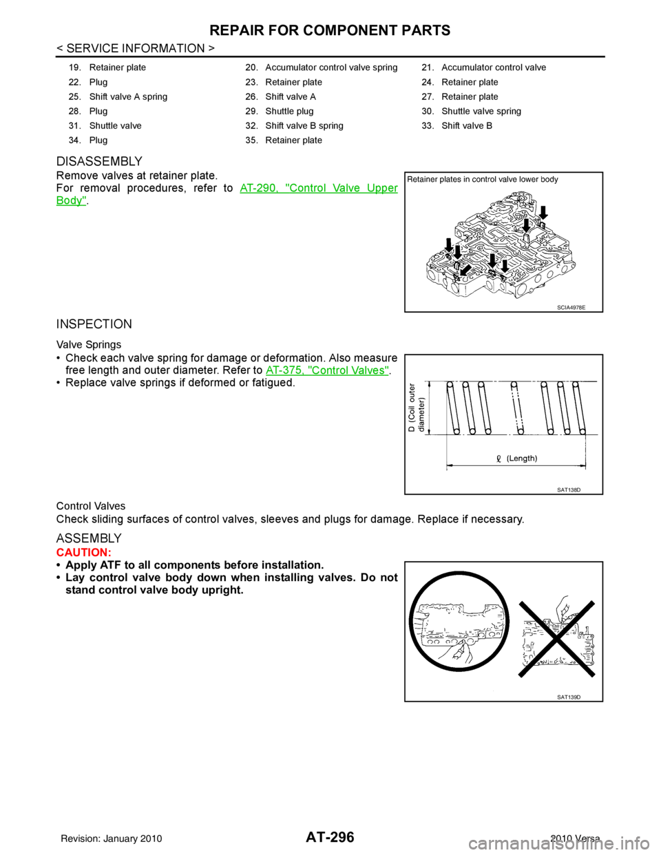
Remove valves at retainer plate.
For removal procedures, refer to AT-290, "
Control Valve Upper
Body".
INSPECTION
Valve Springs
• Check each valve spring for damage or deformation. Also measure
free length and outer diameter. Refer to AT-375, "
Control Valves".
• Replace valve springs if deformed or fatigued.
Control Valves
Check sliding surfaces of control valves, sl eeves and plugs for damage. Replace if necessary.
ASSEMBLY
CAUTION:
• Apply ATF to all components before installation.
• Lay control valve body down wh en installing valves. Do not
stand control valve body upright.
19. Retainer plate 20. Accumulator control valve spring 21. Accumulator control valve
22. Plug 23. Retainer plate24. Retainer plate
25. Shift valve A spring 26. Shift valve A27. Retainer plate
28. Plug 29. Shuttle plug 30. Shuttle valve spring
31. Shuttle valve 32. Shift valve B spring33. Shift valve B
34. Plug 35. Retainer plate
SCIA4978E
SAT138D
SAT139D
Revision: January 20102010 Versa
Page 314 of 3745

REPAIR FOR COMPONENT PARTSAT-297
< SERVICE INFORMATION >
DE
F
G H
I
J
K L
M A
B
AT
N
O P
Install control valves.
For installation procedures, refer to AT-290, "
Control Valve Upper
Body".
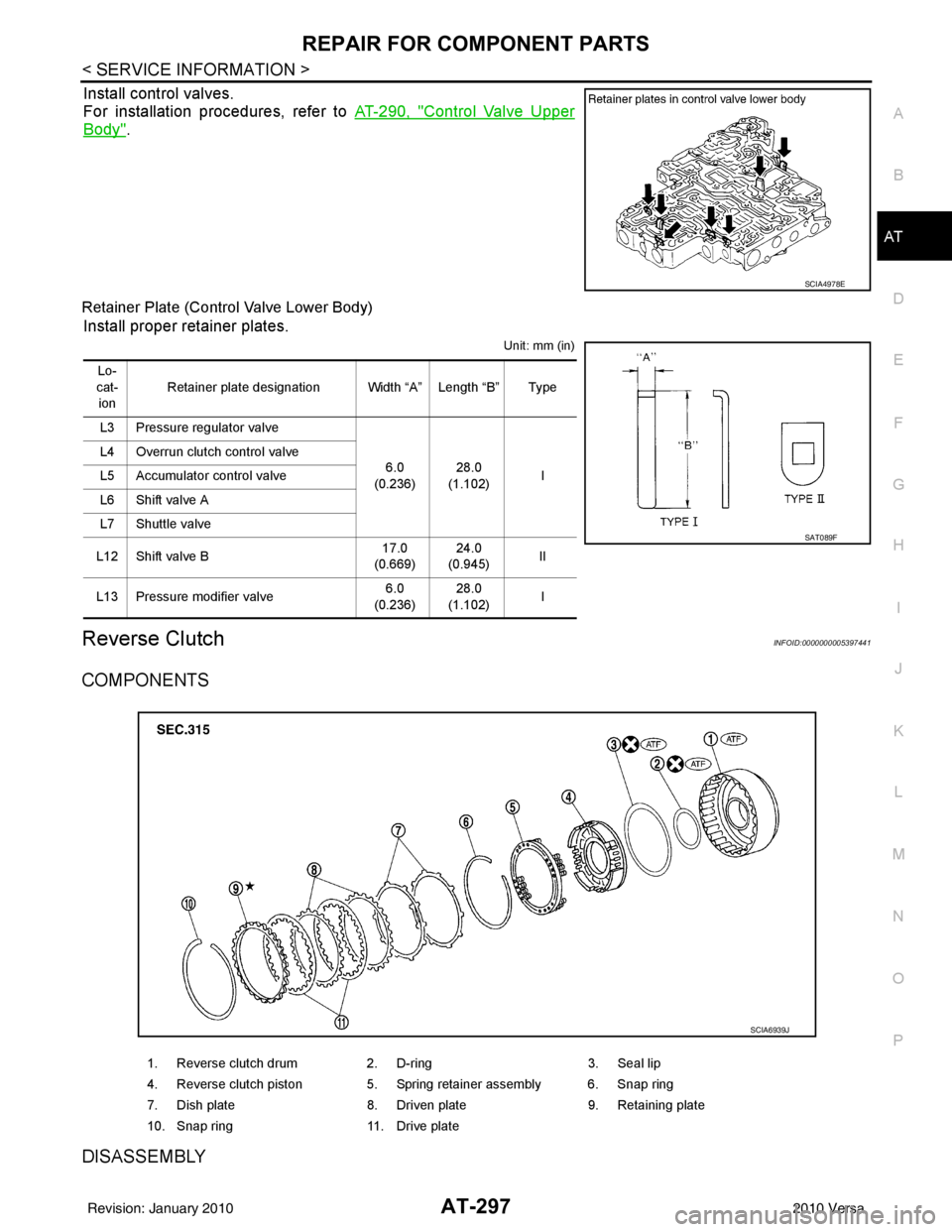
Retainer Plate (Control Valve Lower Body)
Install proper retainer plates.
Unit: mm (in)
Reverse ClutchINFOID:0000000005397441
COMPONENTS
DISASSEMBLY
SCIA4978E
Lo-
cat- ion Retainer plate designation Width “A” Length “B” Type
L3 Pressure regulator valve 6.0
(0.236) 28.0
(1.102) I
L4 Overrun clutch control valve
L5 Accumulator control valve
L6 Shift valve A
L7 Shuttle valve
L12 Shift valve B 17.0
(0.669) 24.0
(0.945) II
L13 Pressure modifier valve 6.0
(0.236) 28.0
(1.102) I
SAT089F
1. Reverse clutch drum
2. D-ring 3. Seal lip
4. Reverse clutch piston 5. Spring retainer assembly 6. Snap ring
7. Dish plate 8. Driven plate 9. Retaining plate
10. Snap ring 11. Drive plate
SCIA6939J
Revision: January 20102010 Versa
Page 386 of 3745

ASSEMBLYAT-369
< SERVICE INFORMATION >
DE
F
G H
I
J
K L
M A
B
AT
N
O P
28. Install lip seals (1) for band servo oil holes on transaxle case.
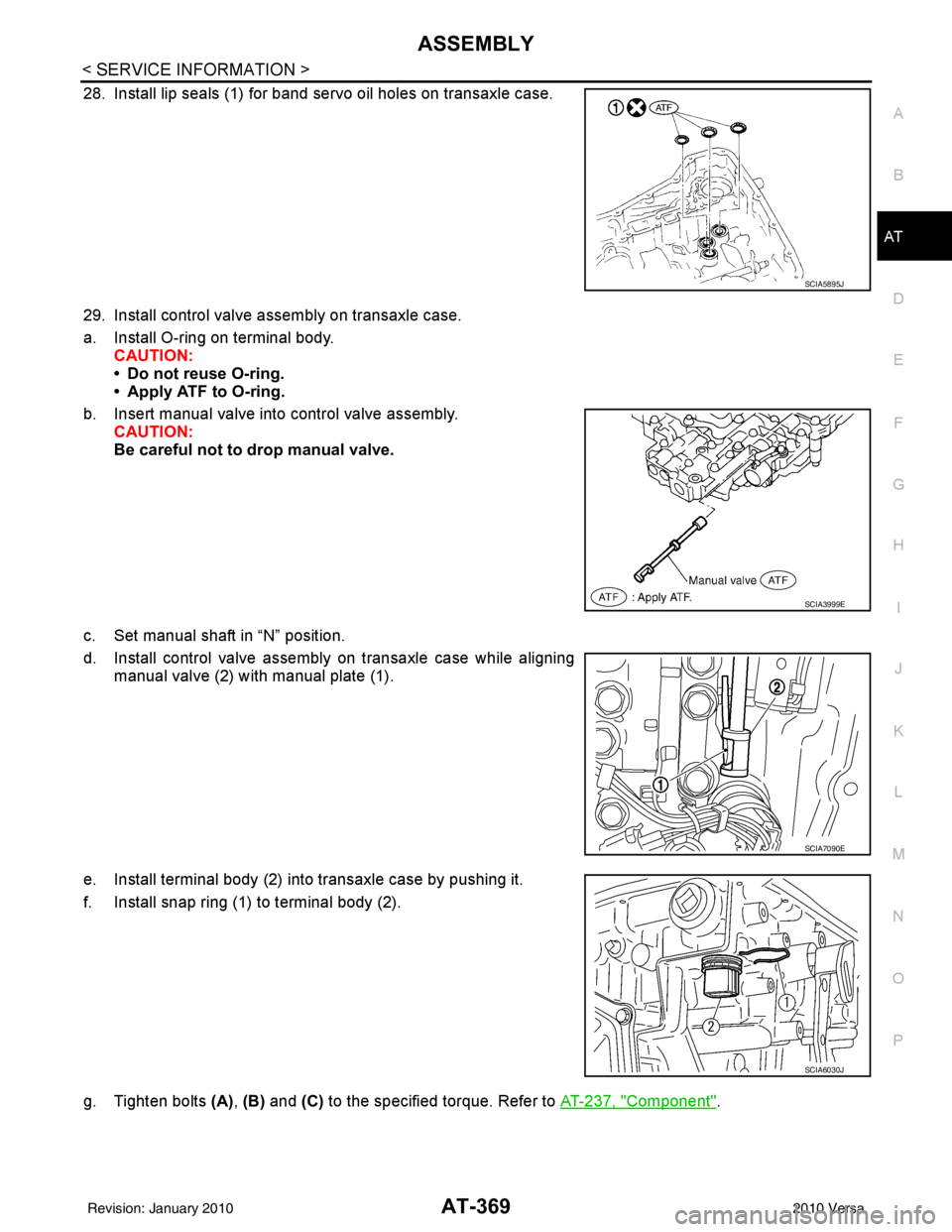
29. Install control valve assembly on transaxle case.
a. Install O-ring on terminal body. CAUTION:
• Do not reuse O-ring.
• Apply ATF to O-ring.
b. Insert manual valve into control valve assembly. CAUTION:
Be careful not to drop manual valve.
c. Set manual shaft in “N” position.
d. Install control valve assembly on transaxle case while aligning manual valve (2) with manual plate (1).
e. Install terminal body (2) into transaxle case by pushing it.
f. Install snap ring (1) to terminal body (2).
g. Tighten bolts (A), (B) and (C) to the specified torque. Refer to AT-237, "
Component".
SCIA5895J
SCIA3999E
SCIA7090E
SCIA6030J
Revision: January 20102010 Versa
Page 392 of 3745

SERVICE DATA AND SPECIFICATIONS (SDS)AT-375
< SERVICE INFORMATION >
DE
F
G H
I
J
K L
M A
B
AT
N
O P
Unit: mm (in)
OUTER DIAMETER AND INNER DIAMETER OF BEARING RACES AND ADJUSTING SHIMS
HR16DE Engine Models
Unit: mm (in)
MR18DE Engine Models
Unit: mm (in)
OUTER DIAMETER OF SNAP RINGS
Unit: mm (in)
INNER DIAMETER OF SNAP RINGS
Unit: mm (in)
Control ValvesINFOID:0000000005397461
CONTROL VALVE SPRINGS
Location Outer diameter Inner diameter
J 72.0 (2.835) 55.5 (2.185)
K, L 82.0 (3.228) 59.0 (2.323)
M 78.5 (3.091) 62.4 (2.457)
LocationOuter diameter Inner diameter
M 48.0 (1.890) 33.0 (1.299)
N 29.0 (1.142) 25.0 (0.984)
O 34.3 (1.350) 26.1 (1.028)
P 79.5 (3.130) 72.0 (2.835)
LocationOuter diameter Inner diameter
N 48.0 (1.890) 33.0 (1.299)
O 34.3 (1.350) 26.1 (1.028)
P 68.0 (2.677) 60.0 (2.632)
Q 72.0 (2.835) 61.0 (2.402)
Location Outer diameter
1 142.0 (5.59)
2
3
162.3 (6.39)
4
5
7 113.0 (4.45)
8 135.4 (5.33)
9 126.0 (4.96)
Location Inner diameter
6 32.0 (1.260)
10 63.5 (2.500)
Revision: January 20102010 Versa
Page 393 of 3745

AT-376
< SERVICE INFORMATION >
SERVICE DATA AND SPECIFICATIONS (SDS)
Unit: mm (in)
AccumulatorINFOID:0000000005397462
RETURN SPRINGS
Unit: mm (in)
Unit: mm (in)
O-RINGS
Unit: mm (in)
Clutches and BrakesINFOID:0000000005397463
REVERSE CLUTCH
Locationspring designation Free length (l) Outer diameter (D)
Upper body L14 Pilot valve spring
38.98 (1.5346)8.9 (0.350)
L15 1–2 accumulator valve spring
20.5 (0.807)6.95 (0.2736)
1–2 accumulator piston spring 55.66 (2.1913)19.5 (0.768)
L16 1st reducing valve spring 27.0 (1.063)7.0 (0.276)
L17 3–2 timing valve spring 23.0 (0.906)6.65 (0.2618)
L18 Overrun clutch reducing valve spring37.5 (1.476)7.0 (0.276)
L19 Torque converter relief valve spring 33.3 (1.311)9.0 (0.354)
L20 Torque converter clutch control valve spring 53.01 (2.0870)6.5 (0.256)
L21 Cooler check valve spring 28.04 (1.1039)7.15 (0.2815)
Lower body L3 Pressure regulator valve spring
45.0 (1.772)15.0 (0.591)
L4 Overrun clutch control valve spring 21.7 (0.854)7.0 (0.276)
L5 Accumulator control valve spring 22.0 (0.866)6.5 (0.256)
L6 Shift valve A spring 21.7 (0.854)7.0 (0.276)
L7 Shuttle valve spring 51.0 (2.008)5.65 (0.2224)
L12 Shift valve B spring 21.7 (0.854)7.0 (0.276)
L13 Pressure modifier valve spring
32.0 (1.260)6.9 (0.272)
Pressure modifier piston spring 30.5 (1.201)9.8 (0.386)
— Line pressure relief valve spring 17.02 (0.6701)8.0 (0.315)
— Torque converter pressure holding spring 9.0 (0.354)7.3 (0.287)
Location Free length (L1)
Servo release accumulator 62.8 (2.472)
LocationLength (L2)
N-D accumulator 46.5 (1.831)
LocationInner diameter (Small) Inner diameter (Large)
Servo release accumulator 26.9 (1.059)44.2 (1.740)
N-D accumulator 34.6 (1.362)39.4 (1.551)
Number of drive plates 2
Number of driven plates 2
Drive plate thickness [mm (in)] Standard
2.0 (0.079)
Allowable limit 1.8 (0.071)
Driven plate thickness [mm (in)] Standard 2.0 (0.079)
Clearance [mm (in)] Standard
0.5 - 0.8 (0.020 - 0.031)
Allowable limit 1.2 (0.047)
Revision: January 20102010 Versa
Page 396 of 3745

SERVICE DATA AND SPECIFICATIONS (SDS)AT-379
< SERVICE INFORMATION >
DE
F
G H
I
J
K L
M A
B
AT
N
O P
Unit: mm (in)
Output ShaftINFOID:0000000005397470
SEAL RING CLEARANCE
SEAL RING
Unit: mm (in)
TURNING TORQUE (FOR HR16DE ENGINE MODELS)
END PLAY (FOR MR18DE ENGINE MODELS)
Bearing RetainerINFOID:0000000005397471
SEAL RING CLEARANCE
Total End PlayINFOID:0000000005397472
Reverse Clutch End PlayINFOID:0000000005397473
Removal and InstallationINFOID:0000000005397474
Shift Solenoid ValvesINFOID:0000000005397475
Return spring Free length
2nd servo return sp ring 32.5 (1.280)
OD servo return sp ring 38.52 (1.5165)
Output shaft seal ring clearance [mm (in)]Standard 0.10 - 0.25 (0.0039 - 0.0098)
Allowable limit
0.25 (0.0098)
Outer diameter Inner diameter Width
29.5 (1.161) 26.2 (1.031)1.95 (0.0768)
Turning torque of output shaft ·m (kg-m, in-lb) 0.25 - 0.88 (0.03 - 0.08, 3 - 7)
Output shaft end play mm (in) 0 - 0.5 (0 - 0.020)
Bearing retainer seal ring clearance [mm (in)]Standard 0.10 - 0.27 (0.0039 - 0.0106)
Allowable limit
0.27 (0.0106)
Total end play [mm (in)] 0.25 - 0.55 (0.0098 - 0.0217)
Reverse clutch end play [mm (in)] 0.65 - 1.0 (0.0256 - 0.039)
Engine HR16DE MR18DE
Distance between end of converter housing and torque converter [mm (in)] 16.2 (0.638)14.4 (0.567)
Gear position 1234
Shift solenoid valve A ON (Closed)OFF (Open)OFF (Open)ON (Closed)
Shift solenoid valve B ON (Closed)ON (Closed) OFF (Open)OFF (Open)
Revision: January 20102010 Versa
Page 397 of 3745

AT-380
< SERVICE INFORMATION >
SERVICE DATA AND SPECIFICATIONS (SDS)
Solenoid Valves
INFOID:0000000005397476
A/T Fluid Temperature SensorINFOID:0000000005397477
Remarks: Specification data are reference values.
Output Speed SensorINFOID:0000000005397478
Dropping ResistorINFOID:0000000005397479
Input Speed SensorINFOID:0000000005397480
Solenoid valve designation Resistance (Approx.)Terminal
Shift solenoid valve A 20 - 30 Ω 2
Shift solenoid valve B 5 - 20 Ω1
Overrun clutch solenoid valve 20 - 30 Ω 3
Line pressure solenoid valve 2.5 - 5.0 Ω 4
Torque converter clutch solenoid valve 5 - 20 Ω 5
Condition Specification (Approx.)
Cold [20 °C (68 °F)]
↓
Hot [80 °C (176 °F)] 1.5V
↓
0.5V 2.5 k
Ω
↓
0.3 k Ω
Condition Judgment standard
When driving at 20 km/h (12 MPH) 150 Hz (Approx.)
Resistance 12Ω (Approx.)
Condition Judgment standard
When driving at 20 km/h (12 MPH) 360 Hz (Approx.)
Revision: January 20102010 Versa
Page 849 of 3745

BR-1
BRAKES
C
DE
G H
I
J
K L
M
SECTION BR
A
B
BR
N
O P
CONTENTS
BRAKE SYSTEM
SERVICE INFORMATION .. ..........................2
PRECAUTIONS .............................................. .....2
Precaution for Supplemental Restraint System
(SRS) "AIR BAG" and "SEAT BELT PRE-TEN-
SIONER" ............................................................. ......
2
Precaution Necessary for Steering Wheel Rota-
tion After Battery Disconnect ............................... ......
2
Precaution for Brake System ....................................3
PREPARATION ...................................................4
Special Service Tool ........................................... ......4
Commercial Service Tool ..........................................4
NOISE, VIBRATION AND HARSHNESS
(NVH) TROUBLESHOOTING .............................
5
NVH Troubleshooting Chart ................................ ......5
BRAKE PEDAL .............................................. .....6
Inspection and Adjustment .................................. ......6
Removal and Installation ...........................................7
BRAKE FLUID ................................................ .....9
On Board Inspection ........................................... ......9
Drain and Refill ..........................................................9
Bleeding Brake System .............................................9
BRAKE TUBE AND HOSE ................................11
Hydraulic Circuit .................................................. ....11
Front Brake Tube and Hose ....................................12
Rear Brake Tube and Hose ....................................12
Inspection After Installation .....................................13
DUAL PROPORTIONING VALVE .....................14
Removal and Installation .........................................14
Inspection ............................................................ ....14
BRAKE MASTER CYLINDER ........................ ....15
On-Board Inspection ........................................... ....15
Removal and Installation ..................................... ....15
Disassembly and Assembly .....................................16
BRAKE BOOSTER ...........................................20
On Board Inspection ............................................ ....20
Removal and Installation .........................................21
VACUUM LINES ...............................................23
Component ..............................................................23
Removal and Installation .........................................23
Inspection ................................................................23
FRONT DISC BRAKE .......................................25
On Board Inspection ............................................ ....25
Component ..............................................................25
Removal and Installation of Brake Pad ...................26
Removal and Installation of Brake Caliper Assem-
bly ........................................................................ ....
30
Disassembly and Assembly of Brake Caliper As-
sembly .....................................................................
31
Brake Burnishing Procedure ....................................34
REAR DRUM BRAKE .......................................35
Component .......................................................... ....35
Removal and Installation of Drum Brake Assembly
....
36
Removal and Installation of Wheel Cylinder ............39
Disassembly and Assembly of Wheel Cylinder .......39
SERVICE DATA AND SPECIFICATIONS
(SDS) .................................................................
40
General Specification ..............................................40
Brake Pedal .............................................................41
Check Valve ............................................................41
Brake Booster ..........................................................42
Front Disc Brake ......................................................42
Rear Drum Brake .....................................................42
Revision: January 20102010 Versa