Page 221 of 3745
AT-204
< SERVICE INFORMATION >
TROUBLE DIAGNOSIS FOR SYMPTOMS
- Overrun clutch solenoid valve
3. Disassemble A/T. Refer to AT-257, "
Disassembly" .
4. Check the following.
- Overrun clutch assembly. Refer to AT-307, "
Forward and Overrun Clutches" .
- Low & reverse brake assembly. Refer to AT-314, "
Low & Reverse Brake" .
OK or NG
OK >> GO TO 10.
NG >> Repair or replace damaged parts.
10.CHECK SYMPTOM
Check again. Refer to AT-62, "
Cruise Test - Part 3" .
OK or NG
OK >> INSPECTION END
NG >> GO TO 11.
11 .CHECK TCM
1. Check TCM input/output signals. Refer to AT-75, "
TCM Terminal and Reference Value" .
2. If NG, recheck TCM pin terminals for damage or loose connection with harness connector.
OK or NG
OK >> INSPECTION END
NG >> Repair or replace damaged parts.
TCM Self-Diagnosis Does Not ActivateINFOID:0000000005397412
SYMPTOM:
OD OFF indicator lamp does not come on in TCM sel f-diagnostic procedure even if the lamp circuit is
good.
DESCRIPTION
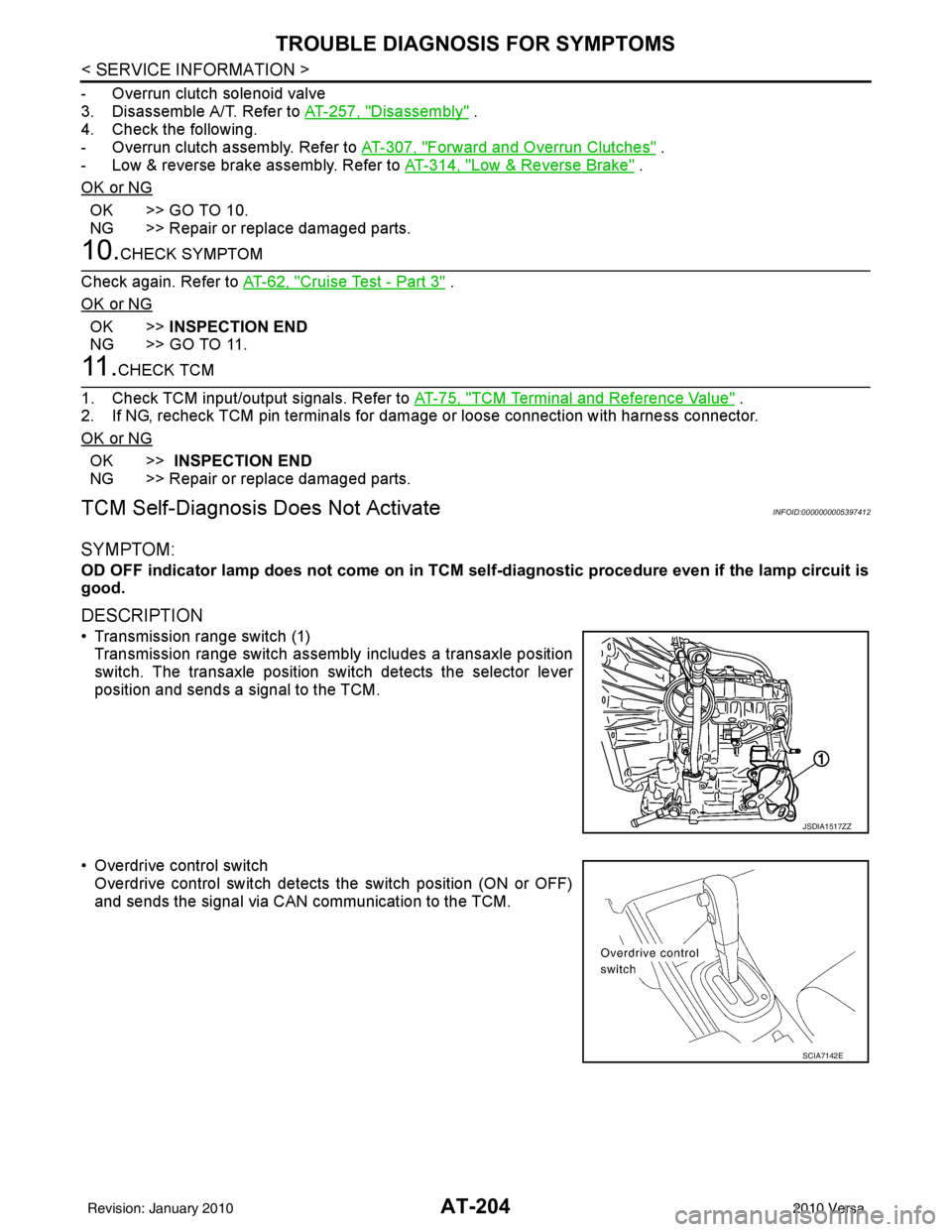
• Transmission range switch (1) Transmission range switch assembly includes a transaxle position
switch. The transaxle position swit ch detects the selector lever
position and sends a signal to the TCM.
• Overdrive control switch Overdrive control switch detects the switch position (ON or OFF)
and sends the signal via CAN communication to the TCM.
JSDIA1517ZZ
SCIA7142E
Revision: January 20102010 Versa
Page 239 of 3745
AT-222
< SERVICE INFORMATION >
ON-VEHICLE SERVICE
ON-VEHICLE SERVICE
Control Valve Assembly and AccumulatorsINFOID:0000000005397424
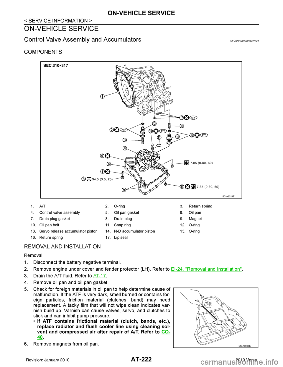
COMPONENTS
REMOVAL AND INSTALLATION
Removal
1. Disconnect the battery negative terminal.
2. Remove engine under cover and fender protector (LH). Refer to EI-24, "
Removal and Installation".
3. Drain the A/T fluid. Refer to AT- 1 7
.
4. Remove oil pan and oil pan gasket.
5. Check for foreign materials in oil pan to help determine cause of malfunction. If the ATF is very dark, smell burned or contains for-
eign particles, friction material (clutches, band) may need
replacement. A tacky film that will not wipe clean indicates var-
nish build up. Varnish can cause valves, servo, and clutches to
stick and can inhibit pump pressure.
•If ATF contains frictional ma terial (clutch, bands, etc.),
replace radiator and flush cool er line using cleaning sol-
vent and compressed air after repair of A/T. Refer to CO-
40.
6. Remove magnets from oil pan.
1. A/T 2. O-ring 3. Return spring
4. Control valve assembly 5. Oil pan gasket6. Oil pan
7. Drain plug gasket 8. Drain plug9. Magnet
10. Oil pan bolt 11. Snap ring 12. O-ring
13. Servo release accumulator piston 14. N-D accumulator piston 15. O-ring
16. Return spring 17. Lip seal
SCIA8024E
SCIA8025E
Revision: January 20102010 Versa
Page 240 of 3745
ON-VEHICLE SERVICEAT-223
< SERVICE INFORMATION >
DE
F
G H
I
J
K L
M A
B
AT
N
O P
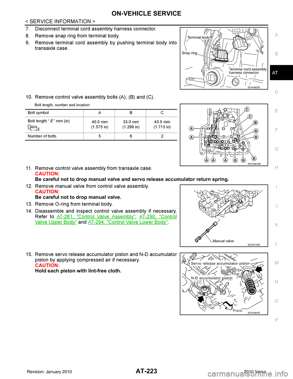
7. Disconnect terminal cord assembly harness connector.
8. Remove snap ring from terminal body.
9. Remove terminal cord assembly by pushing terminal body into transaxle case.
10. Remove control valve assembly bolts (A), (B) and (C).
Bolt length, number and location:
11. Remove control valve assembly from transaxle case. CAUTION:
Be careful not to drop manual valve and servo release accumulato r return spring.
12. Remove manual valve from control valve assembly. CAUTION:
Be careful not to drop manual valve.
13. Remove O-ring from terminal body.
14. Disassemble and inspect control valve assembly if necessary. Refer to AT-281, "
Control Valve Assembly", AT-290, "Control
Valve Upper Body" and AT-294, "Control Valve Lower Body".
15. Remove servo release accumulator piston and N-D accumulator piston by applying compressed air if necessary.
CAUTION:
Hold each piston with lint-free cloth.
SCIA4853E
Bolt symbol ABC
Bolt length “ ” mm (in) 40.0 mm
(1.575 in) 33.0 mm
(1.299 in) 43.5 mm
(1.713 in)
Number of bolts 562
WCIA0649E
SCIA3150E
SCIA4854E
Revision: January 20102010 Versa
Page 241 of 3745
AT-224
< SERVICE INFORMATION >
ON-VEHICLE SERVICE
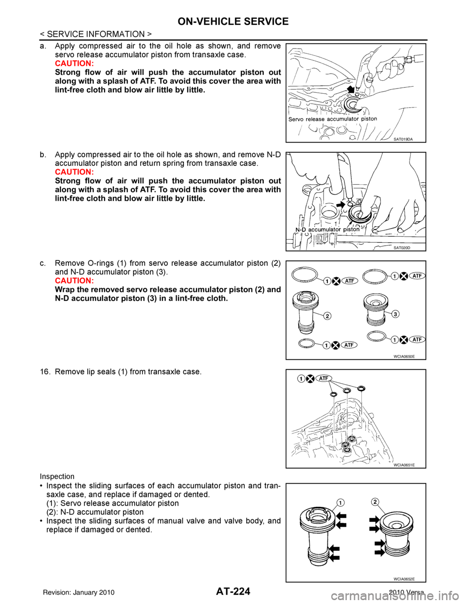
a. Apply compressed air to the oil hole as shown, and removeservo release accumulator piston from transaxle case.
CAUTION:
Strong flow of air will push the accumulator piston out
along with a splash of ATF. To avoid this cover the area with
lint-free cloth and blow air little by little.
b. Apply compressed air to the oil hole as shown, and remove N-D accumulator piston and return spring from transaxle case.
CAUTION:
Strong flow of air will push the accumulator piston out
along with a splash of ATF. To avoid this cover the area with
lint-free cloth and blow air little by little.
c. Remove O-rings (1) from servo release accumulator piston (2) and N-D accumulator piston (3).
CAUTION:
Wrap the removed servo release accumulator piston (2) and
N-D accumulator piston (3) in a lint-free cloth.
16. Remove lip seals (1) from transaxle case.
Inspection
• Inspect the sliding surfaces of each accumulator piston and tran- saxle case, and replace if damaged or dented.
(1): Servo release accumulator piston
(2): N-D accumulator piston
• Inspect the sliding surfaces of manual valve and valve body, and replace if damaged or dented.
SAT019DA
SAT020D
WCIA0650E
WCIA0651E
WCIA0652E
Revision: January 20102010 Versa
Page 242 of 3745
ON-VEHICLE SERVICEAT-225
< SERVICE INFORMATION >
DE
F
G H
I
J
K L
M A
B
AT
N
O P
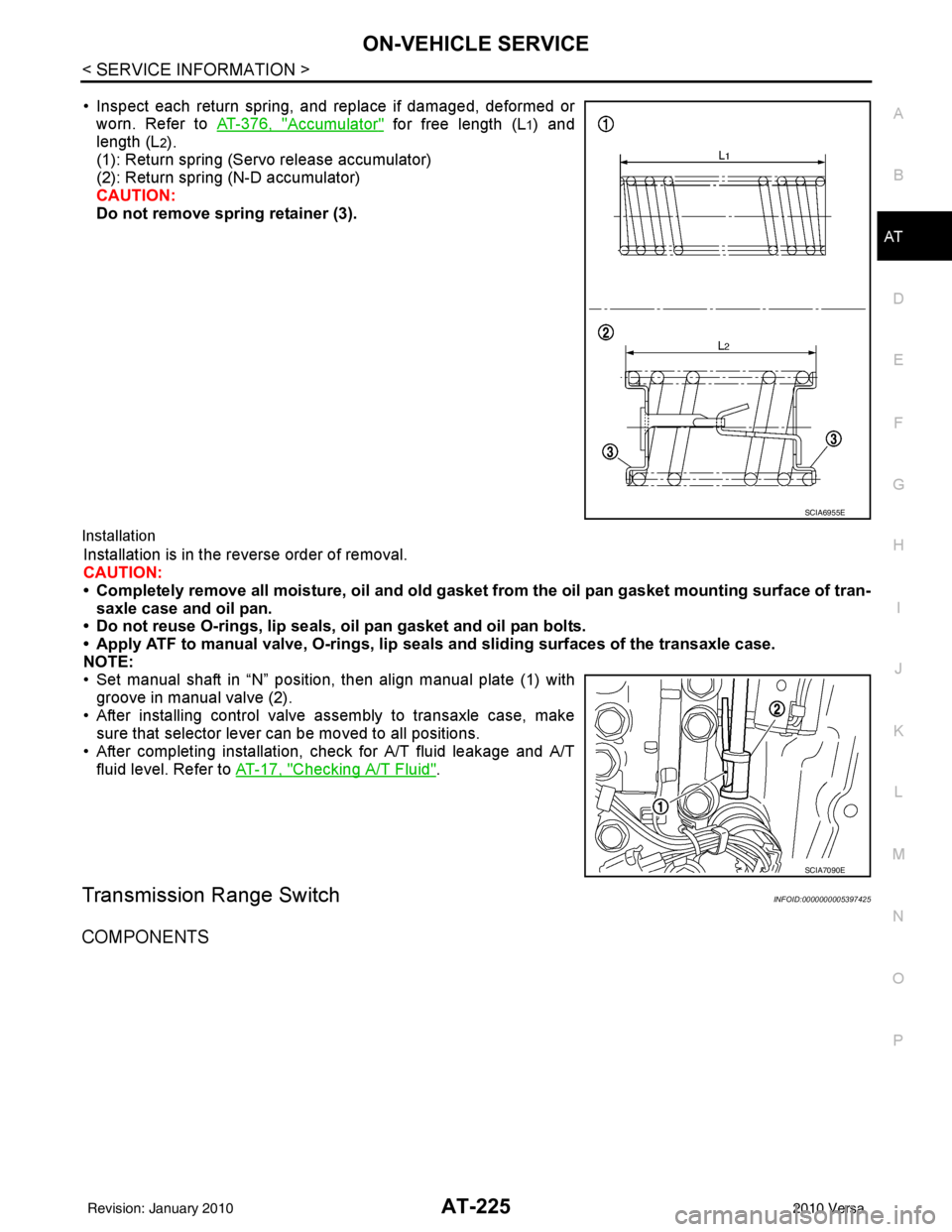
• Inspect each return spring, and replace if damaged, deformed or worn. Refer to AT-376, "
Accumulator" for free length (L1) and
length (L
2).
(1): Return spring (Servo release accumulator)
(2): Return spring (N-D accumulator)
CAUTION:
Do not remove spring retainer (3).
Installation
Installation is in the reverse order of removal.
CAUTION:
• Completely remove all moisture, oil and old gasket from the oil pan gasket mounting surface of tran-
saxle case and oil pan.
• Do not reuse O-rings, lip seals, oil pan gasket and oil pan bolts.
• Apply ATF to manual valve, O-rings, lip seals and sliding surfaces of the transaxle case.
NOTE:
• Set manual shaft in “N” position, then align manual plate (1) with groove in manual valve (2).
• After installing control valve assembly to transaxle case, make sure that selector lever can be moved to all positions.
• After completing installation, check for A/T fluid leakage and A/T fluid level. Refer to AT-17, "
Checking A/T Fluid".
Transmission Range SwitchINFOID:0000000005397425
COMPONENTS
SCIA6955E
SCIA7090E
Revision: January 20102010 Versa
Page 260 of 3745

OVERHAULAT-243
< SERVICE INFORMATION >
DE
F
G H
I
J
K L
M A
B
AT
N
O P
MR18DE ENGINE MODELS
16. Servo release accumulator piston 17. Return spring
18. Control valve assembly
19. Oil pan gasket 20. Oil pan 21. Drain plug gasket
22. Drain plug 23. Magnet 24. Oil pan bolt
25. Snap ring 26. O-ring 27. O-ring
28. N-D accumulator piston 29. Return spring 30. O-ring
31. Lip seal 32. Input speed sensor 33. O-ring
34. Retaining pin 35. Detent spring 36. Retaining pin
37. Manual shaft 38. Manual shaft oil seal 39. Manual plate
40. Parking rod plate 41. Parking rod 42. OD servo piston retainer
43. Snap ring 44. O-ring 45. OD servo piston
46. D-ring 47. Servo release accumulator piston 48. O-ring
49. E-ring 50. Spring retainer 51. OD servo return spring
52. D-ring 53. Band servo piston 54. Band servo thrust washer
55. Band servo piston stem 56. 2nd servo return spring 57. Transmission range switch
58. Parking shaft 59. Return spring 60. Output gear adjusting spac-
er
61. Output gear bearing 62. Output gear 63. Side cover gasket
64. Side cover 65. Side cover bolt 66. Lock nut
67. Idler gear 68. Idler gear bearing 69. Reduction pinion gear ad-
justing shim
70. Parking actuator support 71. Parking pawl 72. LH differential side oil seal
73. Output speed sensor
: Apply Genuine Anaerobic Liquid Gasket or equivalent.
Revision: January 20102010 Versa
Page 266 of 3745
OVERHAULAT-249
< SERVICE INFORMATION >
DE
F
G H
I
J
K L
M A
B
AT
N
O P
1. Snap ring 2. Governor cap3. O-ring
4. Lock nut 5. Anchor end pin6. Transaxle case
7. Reduction pinion gear bearing 8. Reduction pinion gear 9. Brake band
10. Snap ring 11. Radial needle bearing12. Seal ring
13. Bearing retainer 14. O-ring15. Servo release accumulator piston
16. Return spring 17. Control valve assembly18. Oil pan gasket
SCIA7959E
Revision: January 20102010 Versa
Page 276 of 3745
DISASSEMBLYAT-259
< SERVICE INFORMATION >
DE
F
G H
I
J
K L
M A
B
AT
N
O P
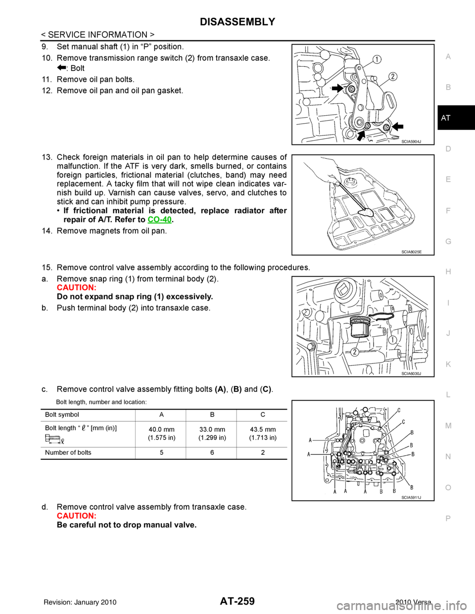
9. Set manual shaft (1) in “P” position.
10. Remove transmission range switch (2) from transaxle case. : Bolt
11. Remove oil pan bolts.
12. Remove oil pan and oil pan gasket.
13. Check foreign materials in oil pan to help determine causes of malfunction. If the ATF is very dark, smells burned, or contains
foreign particles, frictional material (clutches, band) may need
replacement. A tacky film that will not wipe clean indicates var-
nish build up. Varnish can cause valves, servo, and clutches to
stick and can inhibit pump pressure.
•If frictional material is detected, replace radiator after
repair of A/T. Refer to CO-40
.
14. Remove magnets from oil pan.
15. Remove control valve assembly according to the following procedures.
a. Remove snap ring (1) from terminal body (2). CAUTION:
Do not expand snap ring (1) excessively.
b. Push terminal body (2) into transaxle case.
c. Remove control valve assembly fitting bolts (A), (B) and ( C).
Bolt length, number and location:
d. Remove control valve assembly from transaxle case.
CAUTION:
Be careful not to drop manual valve.
SCIA5904J
SCIA8025E
SCIA6030J
Bolt symbol ABC
Bolt length “ ” [mm (in)] 40.0 mm
(1.575 in) 33.0 mm
(1.299 in) 43.5 mm
(1.713 in)
Number of bolts 562
SCIA5911J
Revision: January 20102010 Versa