2010 JAGUAR XFR Interior
[x] Cancel search: InteriorPage 2171 of 3039
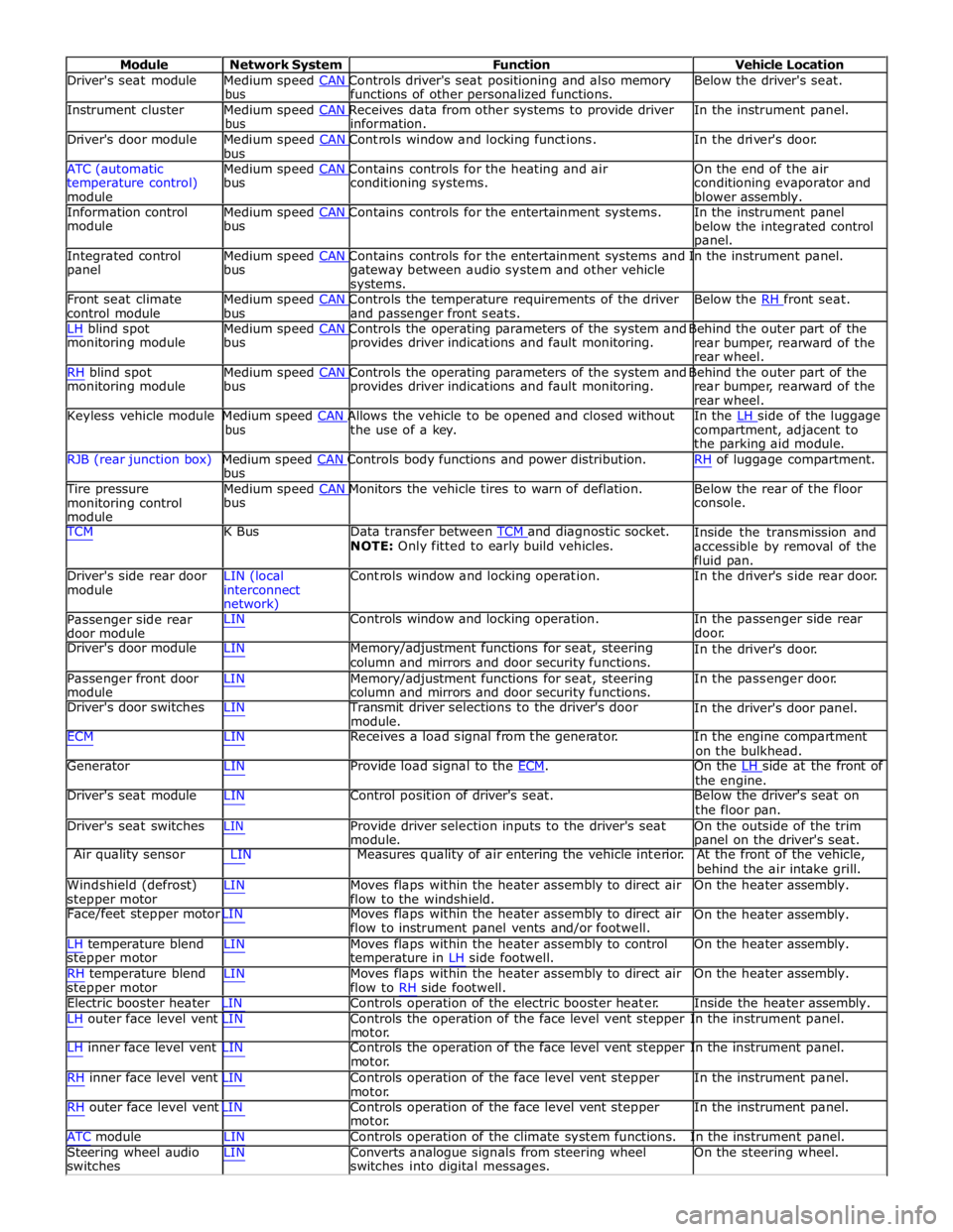
Module Network System Function Vehicle Location
Driver's seat module Medium speed CAN Controls driver's seat positioning and also memory Below the driver's seat. bus functions of other personalized functions.
Instrument cluster Medium speed CAN Receives data from other systems to provide driver In the instrument panel. bus information.
Driver's door module Medium speed CAN Controls window and locking functions. In the driver's door. bus
ATC (automatic Medium speed CAN Contains controls for the heating and air On the end of the air
temperature control)
module bus conditioning systems.
conditioning evaporator and
blower assembly.
Information control Medium speed CAN Contains controls for the entertainment systems. In the instrument panel module bus
below the integrated control
panel.
Integrated control Medium speed CAN Contains controls for the entertainment systems and In the instrument panel. panel bus
gateway between audio system and other vehicle
systems.
Front seat climate Medium speed CAN Controls the temperature requirements of the driver Below the RH front seat. control module bus and passenger front seats.
LH blind spot Medium speed CAN Controls the operating parameters of the system and Behind the outer part of the monitoring module bus provides driver indications and fault monitoring.
rear bumper, rearward of the
rear wheel.
RH blind spot Medium speed CAN Controls the operating parameters of the system and Behind the outer part of the monitoring module bus provides driver indications and fault monitoring.
rear bumper, rearward of the
rear wheel.
Keyless vehicle module Medium speed CAN Allows the vehicle to be opened and closed without In the LH side of the luggage bus the use of a key.
compartment, adjacent to
the parking aid module.
RJB (rear junction box) Medium speed CAN Controls body functions and power distribution. RH of luggage compartment. bus
Tire pressure Medium speed CAN Monitors the vehicle tires to warn of deflation. Below the rear of the floor monitoring control
module bus console.
TCM K Bus Data transfer between TCM and diagnostic socket. NOTE: Only fitted to early build vehicles. Inside the transmission and
accessible by removal of the
fluid pan.
Driver's side rear door
module LIN (local
interconnect
network) Controls window and locking operation. In the driver's side rear door.
Passenger side rear
door module LIN Controls window and locking operation. In the passenger side rear
door.
Driver's door module LIN Memory/adjustment functions for seat, steering
column and mirrors and door security functions. In the driver's door.
Passenger front door
module LIN Memory/adjustment functions for seat, steering
column and mirrors and door security functions. In the passenger door.
Driver's door switches LIN Transmit driver selections to the driver's door
module. In the driver's door panel.
ECM LIN Receives a load signal from the generator. In the engine compartment
on the bulkhead.
Generator LIN Provide load signal to the ECM. On the LH side at the front of the engine.
Driver's seat module LIN Control position of driver's seat. Below the driver's seat on
the floor pan.
Driver's seat switches LIN Provide driver selection inputs to the driver's seat
module. On the outside of the trim
panel on the driver's seat.
Air quality sensor LIN Measures quality of air entering the vehicle interior. At the front of the vehicle,
behind the air intake grill.
Windshield (defrost)
stepper motor LIN Moves flaps within the heater assembly to direct air
flow to the windshield. On the heater assembly.
Face/feet stepper motor LIN Moves flaps within the heater assembly to direct air
flow to instrument panel vents and/or footwell. On the heater assembly.
LH temperature blend
stepper motor
RH temperature blend
stepper motor LIN Moves flaps within the heater assembly to control
temperature in LH side footwell.
LIN Moves flaps within the heater assembly to direct air
flow to RH side footwell. On the heater assembly.
On the heater assembly.
Electric booster heater LIN Controls operation of the electric booster heater. Inside the heater assembly.
LH outer face level vent LIN Controls the operation of the face level vent stepper In the instrument panel.
motor.
LH inner face level vent LIN Controls the operation of the face level vent stepper In the instrument panel.
motor.
RH inner face level vent LIN Controls operation of the face level vent stepper
motor.
RH outer face level vent LIN Controls operation of the face level vent stepper
motor. In the instrument panel.
In the instrument panel.
ATC module LIN Controls operation of the climate system functions. In the instrument panel.
Steering wheel audio
switches LIN Converts analogue signals from steering wheel
switches into digital messages. On the steering wheel.
Page 2172 of 3039
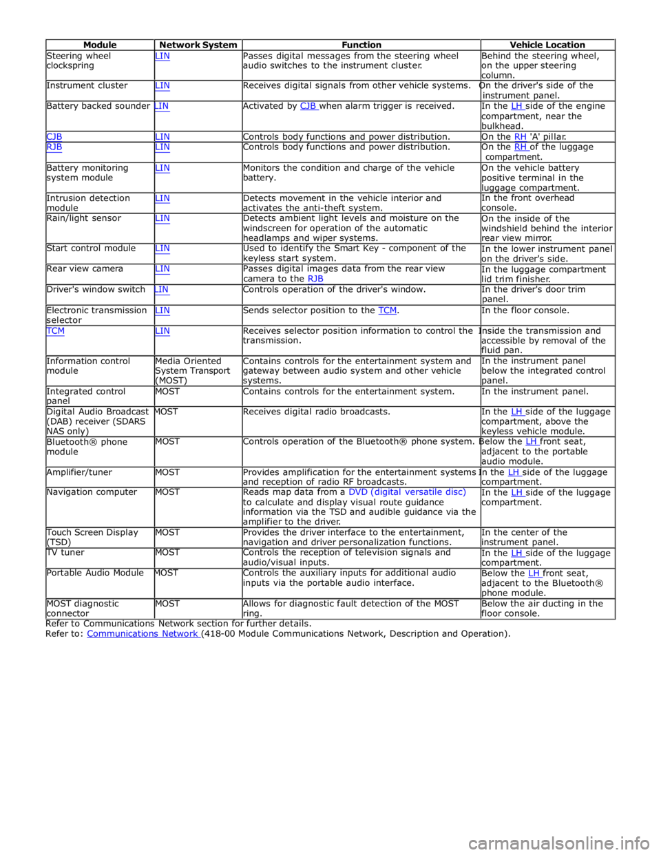
Module Network System Function Vehicle Location
Steering wheel
clockspring LIN Passes digital messages from the steering wheel
audio switches to the instrument cluster. Behind the steering wheel,
on the upper steering
column.
Instrument cluster LIN Receives digital signals from other vehicle systems. On the driver's side of the
instrument panel.
Battery backed sounder LIN Activated by CJB when alarm trigger is received. In the LH side of the engine compartment, near the
bulkhead.
CJB LIN Controls body functions and power distribution. On the RH 'A' pillar.
RJB LIN Controls body functions and power distribution. On the RH of the luggage compartment.
Battery monitoring
system module
Intrusion detection
module LIN Monitors the condition and charge of the vehicle
battery.
LIN Detects movement in the vehicle interior and
activates the anti-theft system. On the vehicle battery
positive terminal in the
luggage compartment.
In the front overhead
console.
Rain/light sensor LIN Detects ambient light levels and moisture on the
windscreen for operation of the automatic
headlamps and wiper systems.
Start control module LIN Used to identify the Smart Key - component of the
keyless start system.
Rear view camera LIN Passes digital images data from the rear view
camera to the RJB On the inside of the
windshield behind the interior
rear view mirror.
In the lower instrument panel
on the driver's side.
In the luggage compartment
lid trim finisher.
Driver's window switch LIN Controls operation of the driver's window. In the driver's door trim
panel.
Electronic transmission
selector LIN Sends selector position to the TCM. In the floor console. TCM LIN Receives selector position information to control the Inside the transmission and
Information control
module
Media Oriented
System Transport
(MOST) transmission.
Contains controls for the entertainment system and
gateway between audio system and other vehicle
systems. accessible by removal of the
fluid pan.
In the instrument panel
below the integrated control
panel.
Integrated control
panel MOST Contains controls for the entertainment system. In the instrument panel.
Digital Audio Broadcast MOST Receives digital radio broadcasts. In the LH side of the luggage (DAB) receiver (SDARS
NAS only)
Bluetooth® phone
module compartment, above the
keyless vehicle module.
MOST Controls operation of the Bluetooth® phone system. Below the LH front seat, adjacent to the portable
audio module.
Amplifier/tuner MOST Provides amplification for the entertainment systems In the LH side of the luggage and reception of radio RF broadcasts.
Navigation computer MOST Reads map data from a DVD (digital versatile disc)
to calculate and display visual route guidance
information via the TSD and audible guidance via the
amplifier to the driver. compartment.
In the LH side of the luggage compartment.
Touch Screen Display
(TSD) MOST Provides the driver interface to the entertainment,
navigation and driver personalization functions. In the center of the
instrument panel.
TV tuner MOST Controls the reception of television signals and
audio/visual inputs.
Portable Audio Module MOST Controls the auxiliary inputs for additional audio
inputs via the portable audio interface. In the LH side of the luggage compartment.
Below the LH front seat, adjacent to the Bluetooth®
phone module.
MOST diagnostic
connector MOST Allows for diagnostic fault detection of the MOST
ring. Below the air ducting in the
floor console.
Refer to Communications Network section for further details.
Refer to: Communications Network (418-00 Module Communications Network, Description and Operation).
Page 2178 of 3039
Published: 11-May-2011
Multifunction Electronic Modules - Remote Keyless Entry (RKE) Module
Diagnosis and Testing
Principles of Operation
For a detailed description of the Remote Keyless Entry system, refer to the relevant Description and Operation sections in the
workshop manual. REFER to: (419-10 Multifunction Electronic Modules)
Module Controlled Functions (Description and Operation), Module Controlled Functions (Description and Operation), Module Controlled Functions (Description and Operation).
Inspection and Verification
CAUTION: Diagnosis by substitution from a donor vehicle is NOT acceptable. Substitution of control modules does not
guarantee confirmation of a fault, and may also cause additional faults in the vehicle being tested and/or the donor vehicle.
1. Verify the customer concern.
2. Visually inspect for obvious signs of damage and system integrity.
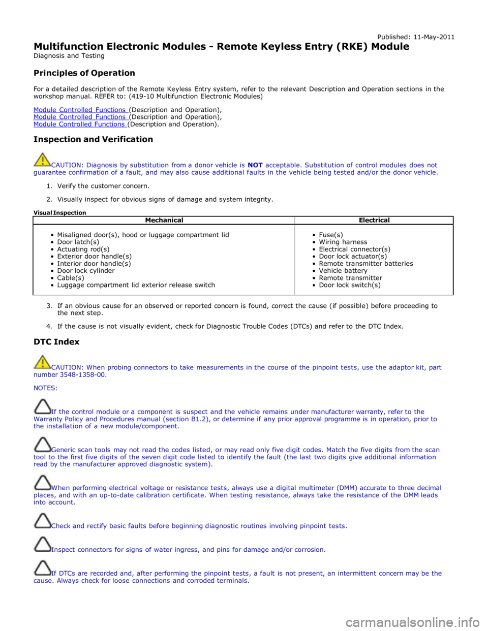
Visual Inspection
Mechanical Electrical
Misaligned door(s), hood or luggage compartment lid
Door latch(s)
Actuating rod(s)
Exterior door handle(s)
Interior door handle(s)
Door lock cylinder
Cable(s)
Luggage compartment lid exterior release switch
Fuse(s)
Wiring harness
Electrical connector(s)
Door lock actuator(s)
Remote transmitter batteries
Vehicle battery
Remote transmitter
Door lock switch(s)
3. If an obvious cause for an observed or reported concern is found, correct the cause (if possible) before proceeding to
the next step.
4. If the cause is not visually evident, check for Diagnostic Trouble Codes (DTCs) and refer to the DTC Index.
DTC Index
CAUTION: When probing connectors to take measurements in the course of the pinpoint tests, use the adaptor kit, part
number 3548-1358-00.
NOTES:
If the control module or a component is suspect and the vehicle remains under manufacturer warranty, refer to the
Warranty Policy and Procedures manual (section B1.2), or determine if any prior approval programme is in operation, prior to
the installation of a new module/component.
Generic scan tools may not read the codes listed, or may read only five digit codes. Match the five digits from the scan
tool to the first five digits of the seven digit code listed to identify the fault (the last two digits give additional information
read by the manufacturer approved diagnostic system).
When performing electrical voltage or resistance tests, always use a digital multimeter (DMM) accurate to three decimal
places, and with an up-to-date calibration certificate. When testing resistance, always take the resistance of the DMM leads
into account.
Check and rectify basic faults before beginning diagnostic routines involving pinpoint tests.
Inspect connectors for signs of water ingress, and pins for damage and/or corrosion.
If DTCs are recorded and, after performing the pinpoint tests, a fault is not present, an intermittent concern may be the
cause. Always check for loose connections and corroded terminals.
Page 2179 of 3039

DTC Description Possible Cause Action B102B00 Passive Key
Response Error - general
failure Using the manufacturer approved diagnostic system, clear
all passive keys, re-learn all passive keys B10C100
Left Front Unlock Pull
Switch
No subtype information Carry out any pinpoint tests associated with this DTC using
the manufacturer approved diagnostic system B10C124
Left Front Unlock Pull
Switch
Signal stuck high - button
stuck in active position Carry out any pinpoint tests associated with this DTC using
the manufacturer approved diagnostic system. Check for
stuck left front unlock switch. Refer to the electrical circuit
diagrams and check left front unlock switch circuit for short
to ground B10C200
Left Rear Unlock Pull
Switch
No subtype information Carry out any pinpoint tests associated with this DTC using
the manufacturer approved diagnostic system B10C224
Left Rear Unlock Pull
Switch
Signal stuck high - button
stuck in active position Carry out any pinpoint tests associated with this DTC using
the manufacturer approved diagnostic system. Check for
stuck left rear unlock switch. Refer to the electrical circuit
diagrams and check left rear unlock switch circuit for short
to ground B10C300
Right Front Unlock
Pull Switch
No subtype information Carry out any pinpoint tests associated with this DTC using
the manufacturer approved diagnostic system B10C324
Right Front Unlock
Pull Switch
Signal stuck high - button
stuck in active position Carry out any pinpoint tests associated with this DTC using
the manufacturer approved diagnostic system. Check for
stuck right front unlock switch. Refer to the electrical circuit
diagrams and check right front unlock switch circuit for
short to ground B10C400
Right Rear Unlock Pull
Switch
No subtype information Carry out any pinpoint tests associated with this DTC using
the manufacturer approved diagnostic system B10C424
Right Rear Unlock Pull
Switch
Signal stuck high - button
stuck in active position Carry out any pinpoint tests associated with this DTC using
the manufacturer approved diagnostic system. Check for
stuck right rear unlock switch. Refer to the electrical circuit
diagrams and check right front unlock switch circuit for
short to ground B10C524 Trunk Unlock Pull
Switch
Signal stuck high - button
stuck in active position Carry out any pinpoint tests associated with this DTC using
the manufacturer approved diagnostic system. Check for
stuck luggage compartment lid unlock switch. Refer to the
electrical circuit diagrams and check luggage compartment
lid unlock switch circuit for short to ground B10C61F
Exterior Trunk
Antenna
Circuit intermittent -
general electrical error Carry out any pinpoint tests associated with this DTC using
the manufacturer approved diagnostic system. Refer to the
electrical circuit diagrams and check exterior luggage
compartment antenna circuits for short to ground, power, open circuit B10C71F
Interior Trunk
Antenna
Circuit intermittent -
general electrical error Carry out any pinpoint tests associated with this DTC using
the manufacturer approved diagnostic system. Refer to the
electrical circuit diagrams and check interior luggage
compartment antenna circuits for short to ground, power, open circuit B10C81F
Interior Center
Antenna
Circuit intermittent -
general electrical error Carry out any pinpoint tests associated with this DTC using
the manufacturer approved diagnostic system. Refer to the
electrical circuit diagrams and check interior center antenna
circuits for short to ground, power, open circuit B10C91F Interior Front Antenna
Circuit intermittent -
general electrical error Carry out any pinpoint tests associated with this DTC using
the manufacturer approved diagnostic system. Refer to the
electrical circuit diagrams and check interior front antenna
circuits for short to ground, power, open circuit B10CA1F
Left Rear Door Handle
Antenna
Circuit intermittent -
general electrical error Carry out any pinpoint tests associated with this DTC using
the manufacturer approved diagnostic system. Refer to the
electrical circuit diagrams and check left rear door handle
antenna circuits for short to ground, power, open circuit B10CB1F
Right Rear Door
Handle Antenna
Circuit intermittent -
general electrical error Carry out any pinpoint tests associated with this DTC using
the manufacturer approved diagnostic system. Refer to the
electrical circuit diagrams and check right rear door handle
antenna circuits for short to ground, power, open circuit B10CC24
Left Front Latch
Clutch Switch
Signal stuck high - button
stuck in active position Check for stuck left front door latch clutch switch. Refer to
the electrical circuit diagrams and check left front door
latch clutch switch circuit for short to ground B10CD24
Left Rear Latch Clutch
Switch
Signal stuck high - button
stuck in active position Check for stuck left rear door latch clutch switch. Refer to
the electrical circuit diagrams and check left rear door latch
clutch switch circuit for short to ground
Page 2187 of 3039
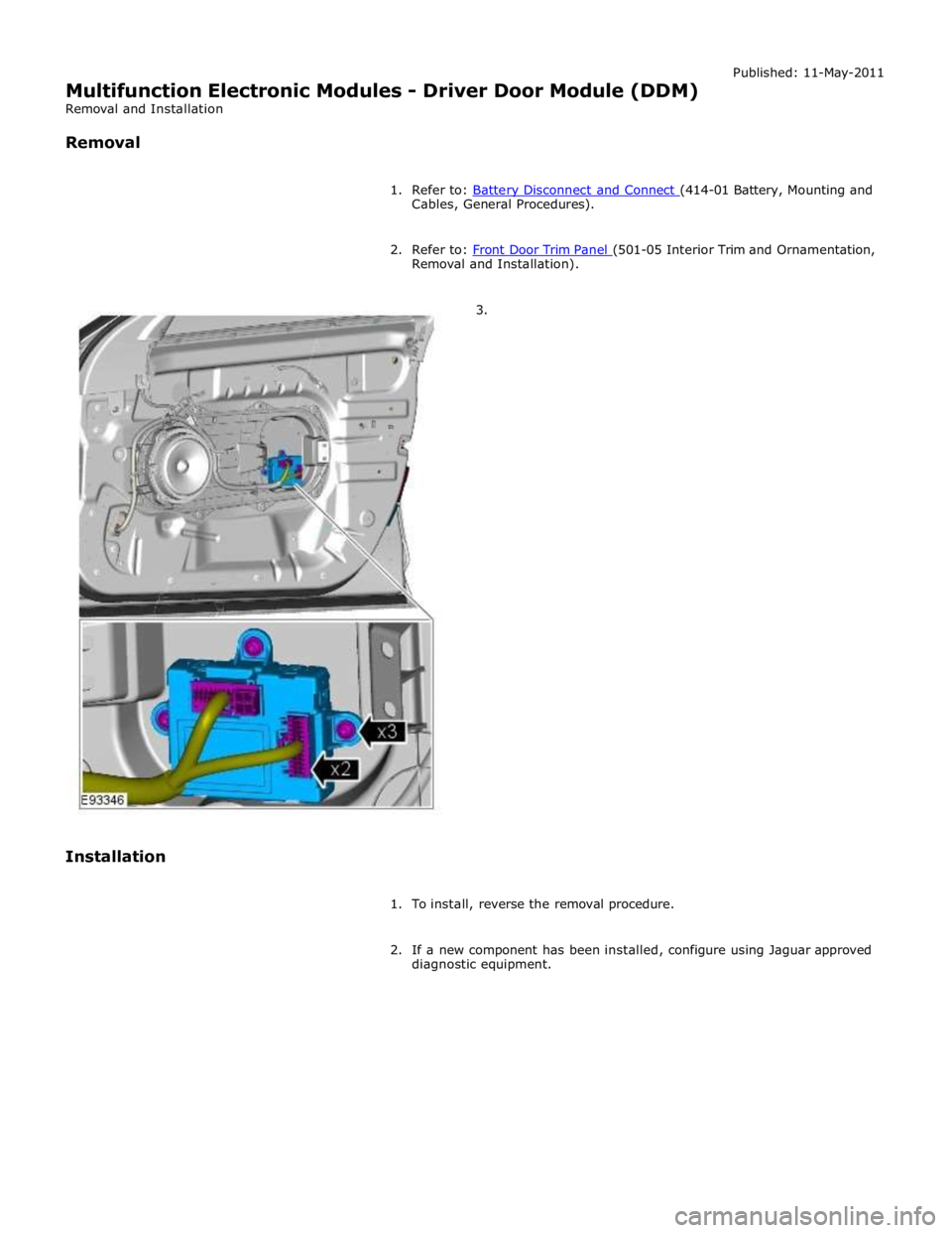
Cables, General Procedures).
2. Refer to: Front Door Trim Panel (501-05 Interior Trim and Ornamentation, Removal and Installation).
3.
Installation
1. To install, reverse the removal procedure.
2. If a new component has been installed, configure using Jaguar approved
diagnostic equipment.
Page 2189 of 3039
Published: 11-May-2011
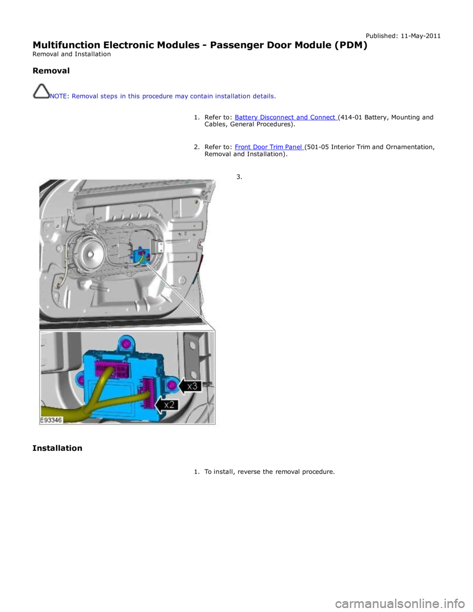
Multifunction Electronic Modules - Passenger Door Module (PDM)
Removal and Installation
Removal
NOTE: Removal steps in this procedure may contain installation details.
1. Refer to: Battery Disconnect and Connect (414-01 Battery, Mounting and Cables, General Procedures).
2. Refer to: Front Door Trim Panel (501-05 Interior Trim and Ornamentation, Removal and Installation).
3.
Installation
1. To install, reverse the removal procedure.
Page 2190 of 3039
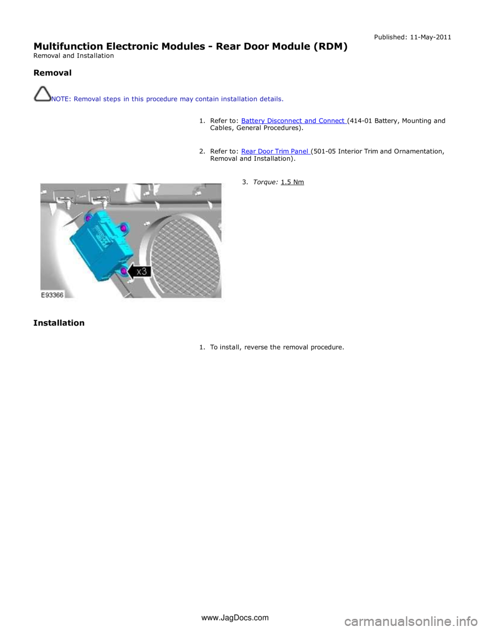
Multifunction Electronic Modules - Rear Door Module (RDM)
Removal and Installation
Removal
NOTE: Removal steps in this procedure may contain installation details. Published: 11-May-2011
1. Refer to: Battery Disconnect and Connect (414-01 Battery, Mounting and Cables, General Procedures).
2. Refer to: Rear Door Trim Panel (501-05 Interior Trim and Ornamentation, Removal and Installation).
Installation
3. Torque: 1.5 Nm
1. To install, reverse the removal procedure. www.JagDocs.com
Page 2218 of 3039
(100-00 General Information, Description and Operation) /
Body Repairs (501-25A Body Repairs - General Information, Description and Operation) /
Corrosion Protection (501-25B Body Repairs - Corrosion Protection, Description and Operation) /
Body and Frame (501-26 Body Repairs - Vehicle Specific Information and Tolerance Checks, Description and Operation).
3. Disconnect the battery ground cable.
For additional information, refer to: Battery Disconnect and Connect (414-01 Battery, Mounting and Cables, General Procedures).
4. Remove the loadspace trim panel RH.
For additional information, refer to: Loadspace Trim Panel RH (501-05 Interior Trim and Ornamentation, Removal and Installation).
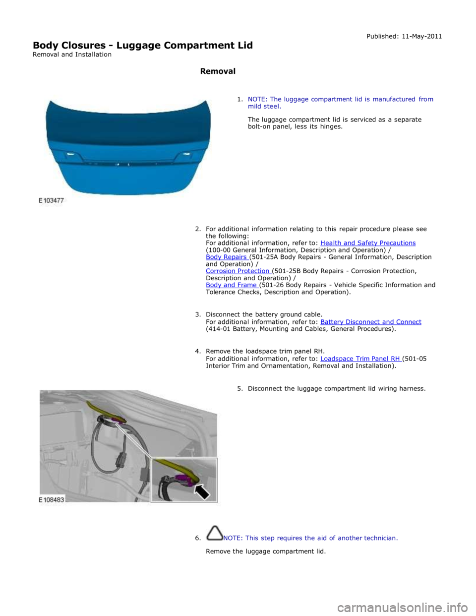
5. Disconnect the luggage compartment lid wiring harness.
6. NOTE: This step requires the aid of another technician.
Remove the luggage compartment lid.