2010 JAGUAR XFR Module
[x] Cancel search: ModulePage 2333 of 3039

DTC Description Possible Cause Action B1C0024
Seat Recline Up
Switch
Signal stuck high Check for a stuck switch. Refer to the electrical circuit
diagrams and check driver seat switch pack to seat
module LIN circuit for short, open circuit and seat
recline up circuit for short to ground B1C0124
Seat Recline Down
Switch
Signal stuck high Check for a stuck switch. Refer to the electrical circuit
diagrams and check driver seat switch pack to seat
module LIN circuit for short, open circuit and check seat
recline down circuit for short to ground B1C0224 Memory Store Switch
Signal stuck high Check for a stuck switch. Refer to the electrical circuit
diagrams and check driver seat switch pack to seat
module LIN circuit for short, open circuit B1C0324 Memory #1 Switch
Signal stuck high Check for a stuck switch. Refer to the electrical circuit
diagrams and check driver seat switch pack to seat
module LIN circuit for short, open circuit B1C0424 Memory #2 Switch
Signal stuck high Check for a stuck switch. Refer to the electrical circuit
diagrams and check driver seat switch pack to seat
module LIN circuit for short, open circuit B1C0524 Memory #3 Switch
Signal stuck high Check for a stuck switch. Refer to the electrical circuit
diagrams and check driver seat switch pack to seat
module LIN circuit for short, open circuit U001088
Medium speed Can
communication Bus
Bus off Carry out any pinpoint tests associated with this DTC
using the manufacturer approved diagnostic system.
Refer to the electrical circuit diagrams and check CAN
network to climate controlled seat module for short, open circuit U014000
Lost communication
with CJB
Lost communication with CJB Carry out any pinpoint tests associated with this DTC
using the manufacturer approved diagnostic system.
Check CJB for related DTCs and refer to the relevant
DTC Index U014200
Lost communication
with RJB
Lost communication with RJB Carry out any pinpoint tests associated with this DTC
using the manufacturer approved diagnostic system.
Check RJB for related DTCs and refer to the relevant
DTC Index U015500
Lost
communications
with instrument
cluster
Lost communications with
instrument cluster Carry out any pinpoint tests associated with this DTC
using the manufacturer approved diagnostic system.
Refer to the electrical circuit diagrams and check CAN
network to climate controlled seat module and
instrument cluster for short, open circuit U019900
Lost communication
with Driver Door
Module (DDM)
Lost communication with DDM Carry out any pinpoint tests associated with this DTC
using the manufacturer approved diagnostic system U030000
Internal control
module software
incompatibility
Invalid configuration message is
received Re-configure the RJB using the manufacturer approved
diagnostic system. Clear the DTC and retest. If the DTC
is still logged suspect the DSM/PSM, refer to the new
module installation note at the top of the DTC Index U1A1449
CAN Initialisation
failure
Internal electronic failure Install a new DSM, refer to the new module installation
note at the top of the DTC Index U1A4C68
Build/end of line
mode active
Manufacturing mode has not
been removed Place DSM in to customer mode using manufacturer
approved diagnostic system U300049 Control module
Internal electronic failure Install a new DSM, refer to the new module installation
note at the top of the DTC Index U300055
Stored vehicle
configuration data
does not match
Incorrect car configuration data
received Re-configure the RJB using the manufacturer approved
diagnostic system. Clear DTC and re-test. If the DTC
remains suspect the DSM, refer to the new module
installation note at the top of the DTC Index U300087 Control Module
Missing message Re-configure the RJB using the manufacturer approved
diagnostic system. Check DSM for DTCs and refer to the
DTC Index. Check CAN network integrity using the
manufacturer approved diagnostic system U300146
Control module
improper shutdown
Calibration/parameter memory
failure Check for DTCs that could indicate power failure to the
module and refer to the DTC Index U300281
Vehicle
Identification
Number (VIN)
Vehicle/component mis-match.
Corrupt VIN data being
transmitted, module previously
installed to other vehicle Install original module, check for DTCs and refer to
relevant DTC Index U300316 Battery Voltage
Circuit voltage below threshold Carry out any pinpoint tests associated with this DTC
using the manufacturer approved diagnostic system
Page 2337 of 3039
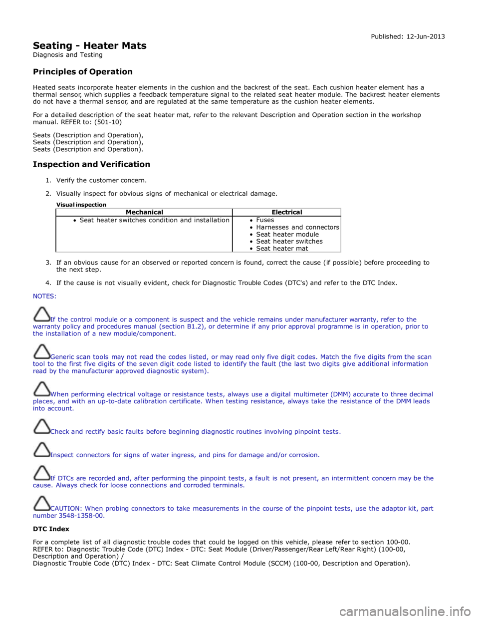
Seating - Heater Mats
Diagnosis and Testing
Principles of Operation Published: 12-Jun-2013
Heated seats incorporate heater elements in the cushion and the backrest of the seat. Each cushion heater element has a
thermal sensor, which supplies a feedback temperature signal to the related seat heater module. The backrest heater elements
do not have a thermal sensor, and are regulated at the same temperature as the cushion heater elements.
For a detailed description of the seat heater mat, refer to the relevant Description and Operation section in the workshop
manual. REFER to: (501-10)
Seats (Description and Operation),
Seats (Description and Operation),
Seats (Description and Operation).
Inspection and Verification
1. Verify the customer concern.
2. Visually inspect for obvious signs of mechanical or electrical damage.
Visual inspection
Mechanical Electrical Seat heater switches condition and installation Fuses
Harnesses and connectors
Seat heater module
Seat heater switches
Seat heater mat
3. If an obvious cause for an observed or reported concern is found, correct the cause (if possible) before proceeding to
the next step.
4. If the cause is not visually evident, check for Diagnostic Trouble Codes (DTC's) and refer to the DTC Index.
NOTES:
If the control module or a component is suspect and the vehicle remains under manufacturer warranty, refer to the
warranty policy and procedures manual (section B1.2), or determine if any prior approval programme is in operation, prior to
the installation of a new module/component.
Generic scan tools may not read the codes listed, or may read only five digit codes. Match the five digits from the scan
tool to the first five digits of the seven digit code listed to identify the fault (the last two digits give additional information
read by the manufacturer approved diagnostic system).
When performing electrical voltage or resistance tests, always use a digital multimeter (DMM) accurate to three decimal
places, and with an up-to-date calibration certificate. When testing resistance, always take the resistance of the DMM leads
into account.
Check and rectify basic faults before beginning diagnostic routines involving pinpoint tests.
Inspect connectors for signs of water ingress, and pins for damage and/or corrosion.
If DTCs are recorded and, after performing the pinpoint tests, a fault is not present, an intermittent concern may be the
cause. Always check for loose connections and corroded terminals.
CAUTION: When probing connectors to take measurements in the course of the pinpoint tests, use the adaptor kit, part
number 3548-1358-00.
DTC Index
For a complete list of all diagnostic trouble codes that could be logged on this vehicle, please refer to section 100-00.
REFER to: Diagnostic Trouble Code (DTC) Index - DTC: Seat Module (Driver/Passenger/Rear Left/Rear Right) (100-00,
Description and Operation) /
Diagnostic Trouble Code (DTC) Index - DTC: Seat Climate Control Module (SCCM) (100-00, Description and Operation).
Page 2339 of 3039
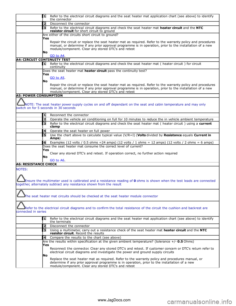
1 Refer to the electrical circuit diagrams and the seat heater mat application chart (see above) to identify the connector 2 Disconnect the connector 3 Refer to the electrical circuit diagrams and check the seat heater mat heater circuit and the NTC resistor circuit for short circuit to ground Are either of the circuits short circuit to ground?
Yes
Repair the circuit or replace the seat heater mat as required. Refer to the warranty policy and procedures
manual, or determine if any prior approval programme is in operation, prior to the installation of a new
module/component. Clear any stored DTC's and retest
No
GO to A4. A4: CIRCUIT CONTINUITY TEST 1 Refer to the electrical circuit diagrams and check the seat heater mat ( heater circuit ) for circuit continuity Does the seat heater mat heater circuit pass the continuity test?
Yes
GO to A5. No
Repair the circuit or replace the seat heater mat as required. Refer to the warranty policy and procedures
manual, or determine if any prior approval programme is in operation, prior to the installation of a new module/component. Clear any stored DTC's and retest A5: POWER CONSUMPTION
NOTE: The seat heater power supply cycles on and off dependant on the seat and cabin temperature and may only
switch on for 5 seconds in 30 seconds 1 Reconnect the connector 2 Operate the vehicle air conditioning on full for 10 minutes to reduce the in vehicle ambient temperature 3 Refer to the electrical circuit diagrams and check the seat heater mat ( heater circuit ) using a current clamp 4 Operate the seat heater on full power 5 Use the chart above to calculate typical value (V/R=I) (Volts divided by Resistance equals Current in Amps) 6 Examples (12 volts / 0.5 ohms =24 amps) (12 volts / 1 ohms = 12 amps) (12 volts / 2 ohms = 6 amps) Does the seat heater mat consume the correct level of current?
Yes
Clear any stored DTC's and retest. If operation correct, no further action required
No
GO to A6. A6: RESISTANCE CHECK NOTES:
Ensure the multimeter used is calibrated and a resistance reading of 0 ohms is shown when the test leads are connected
together, alternately subtract any resistance shown from the result
The seat heater mat circuits should be checked at the seat heater module connector
Refer to the electrical circuit diagrams and to confirm the total resistance of the circuit the cushion and backrest are
connected in series 1 Refer to the electrical circuit diagrams and the seat heater mat application chart (see above) to identify the terminals 2 Disconnect the connector 3 Using a multimeter, carry out a resistance check of the seat heater mat heater circuit and the NTC resistor circuit. Record the results 4 Compare the results to the chart (see above) Are the results within specification at the given ambient temperature? (tolerance +/- 0.5 Ohms)
Yes
Reconnect the connector. Clear any stored DTC's and retest. If customer concern or DTC's return refer to
electrical circuit diagrams and investigate the power and ground supply circuits
No
Replace the seat heater mat as required. Refer to the warranty policy and procedures manual, or
determine if any prior approval programme is in operation, prior to the installation of a new module/component. Clear any stored DTC's and retest www.JagDocs.com
Page 2340 of 3039
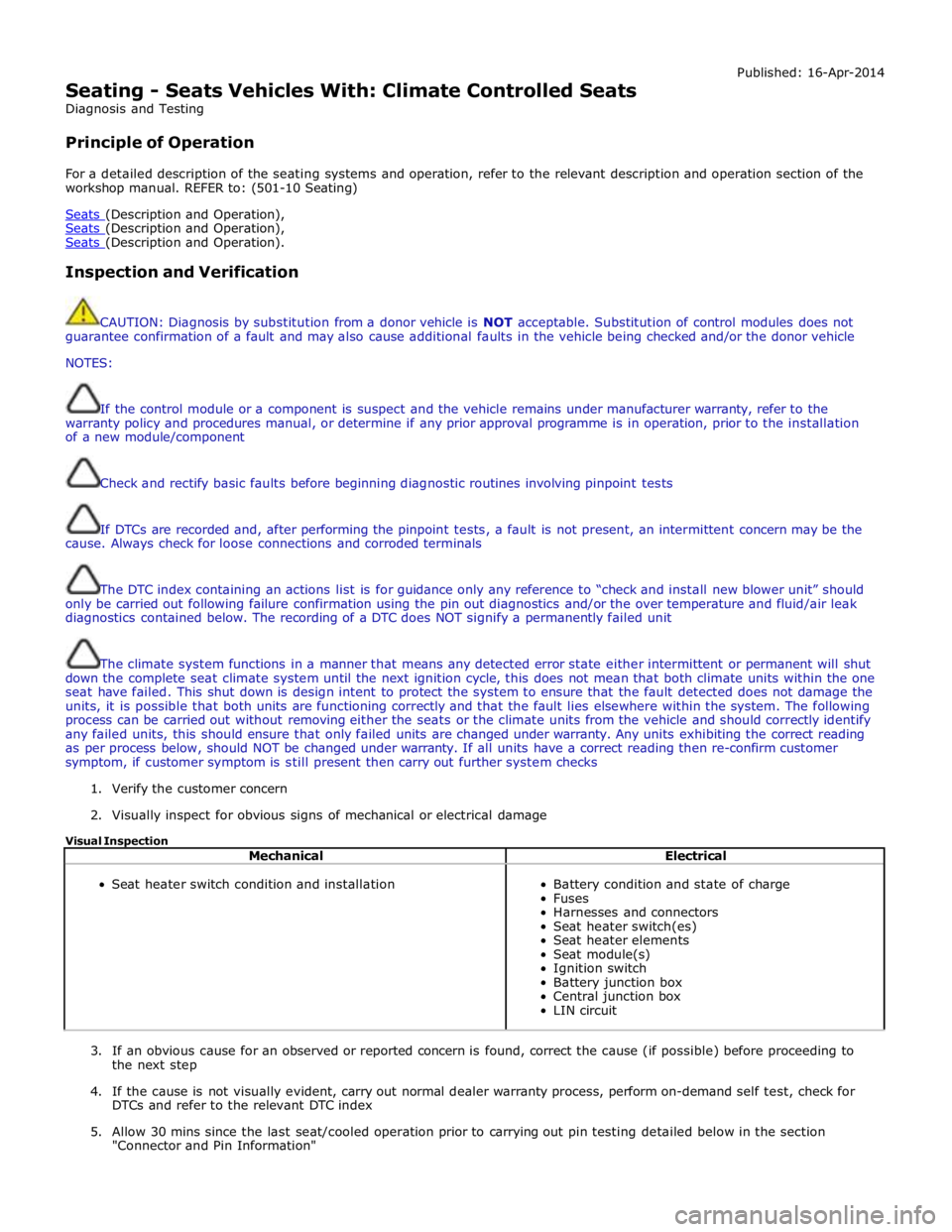
Seating - Seats Vehicles With: Climate Controlled Seats
Diagnosis and Testing
Principle of Operation Published: 16-Apr-2014
For a detailed description of the seating systems and operation, refer to the relevant description and operation section of the
workshop manual. REFER to: (501-10 Seating)
Seats (Description and Operation), Seats (Description and Operation), Seats (Description and Operation).
Inspection and Verification
CAUTION: Diagnosis by substitution from a donor vehicle is NOT acceptable. Substitution of control modules does not
guarantee confirmation of a fault and may also cause additional faults in the vehicle being checked and/or the donor vehicle
NOTES:
If the control module or a component is suspect and the vehicle remains under manufacturer warranty, refer to the
warranty policy and procedures manual, or determine if any prior approval programme is in operation, prior to the installation
of a new module/component
Check and rectify basic faults before beginning diagnostic routines involving pinpoint tests
If DTCs are recorded and, after performing the pinpoint tests, a fault is not present, an intermittent concern may be the
cause. Always check for loose connections and corroded terminals
The DTC index containing an actions list is for guidance only any reference to “check and install new blower unit” should
only be carried out following failure confirmation using the pin out diagnostics and/or the over temperature and fluid/air leak
diagnostics contained below. The recording of a DTC does NOT signify a permanently failed unit
The climate system functions in a manner that means any detected error state either intermittent or permanent will shut
down the complete seat climate system until the next ignition cycle, this does not mean that both climate units within the one
seat have failed. This shut down is design intent to protect the system to ensure that the fault detected does not damage the
units, it is possible that both units are functioning correctly and that the fault lies elsewhere within the system. The following
process can be carried out without removing either the seats or the climate units from the vehicle and should correctly identify
any failed units, this should ensure that only failed units are changed under warranty. Any units exhibiting the correct reading
as per process below, should NOT be changed under warranty. If all units have a correct reading then re-confirm customer
symptom, if customer symptom is still present then carry out further system checks
1. Verify the customer concern
2. Visually inspect for obvious signs of mechanical or electrical damage
Visual Inspection
Mechanical Electrical
Seat heater switch condition and installation
Battery condition and state of charge
Fuses
Harnesses and connectors
Seat heater switch(es)
Seat heater elements
Seat module(s)
Ignition switch
Battery junction box
Central junction box
LIN circuit
3. If an obvious cause for an observed or reported concern is found, correct the cause (if possible) before proceeding to
the next step
4. If the cause is not visually evident, carry out normal dealer warranty process, perform on-demand self test, check for
DTCs and refer to the relevant DTC index
5. Allow 30 mins since the last seat/cooled operation prior to carrying out pin testing detailed below in the section
"Connector and Pin Information"
Page 2341 of 3039
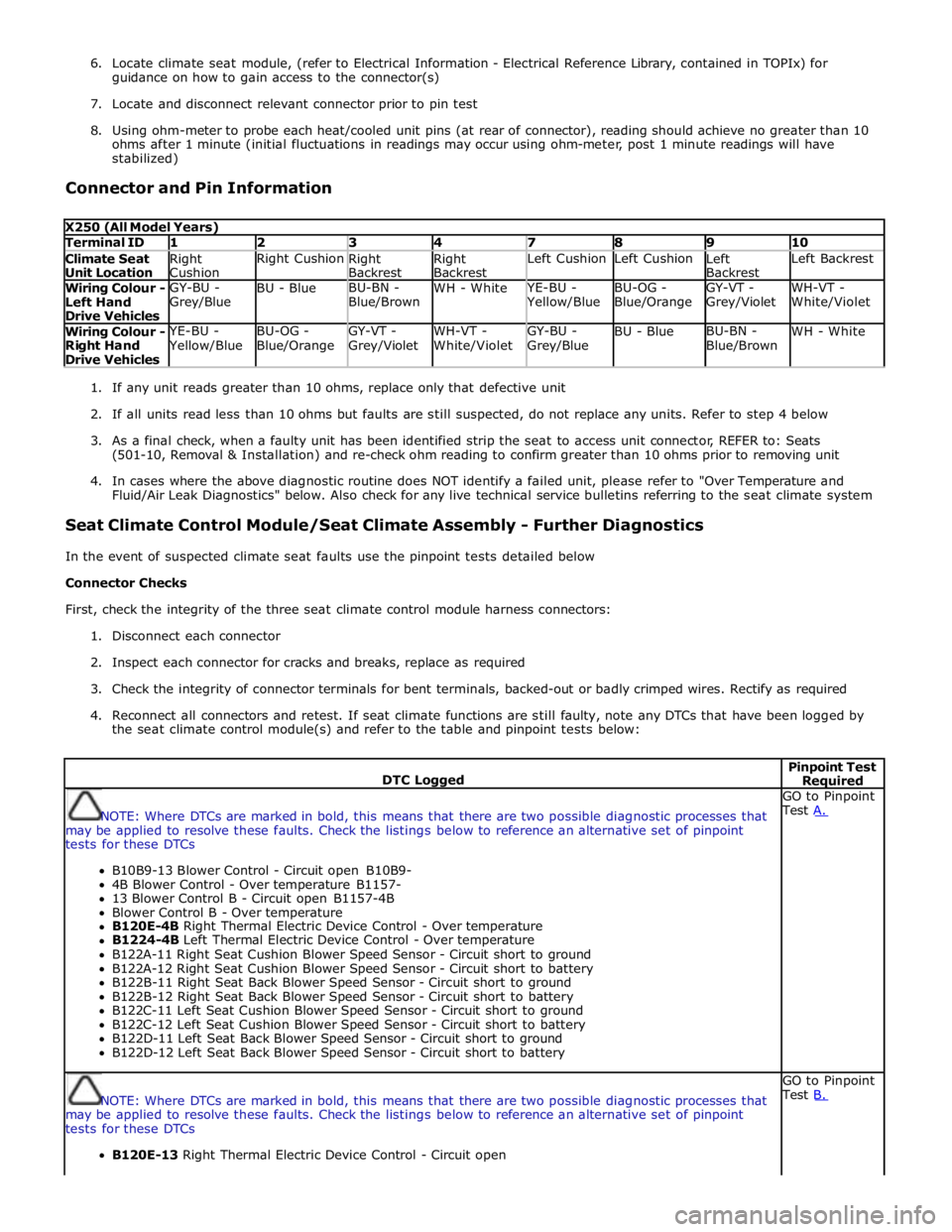
6. Locate climate seat module, (refer to Electrical Information - Electrical Reference Library, contained in TOPIx) for
guidance on how to gain access to the connector(s)
7. Locate and disconnect relevant connector prior to pin test
8. Using ohm-meter to probe each heat/cooled unit pins (at rear of connector), reading should achieve no greater than 10
ohms after 1 minute (initial fluctuations in readings may occur using ohm-meter, post 1 minute readings will have
stabilized)
Connector and Pin Information
X250 (All Model Years) Terminal ID 1 2 3 4 7 8 9 10 Climate Seat
Unit Location Right
Cushion Right Cushion
Right
Backrest Right
Backrest Left Cushion Left Cushion
Left
Backrest Left Backrest Wiring Colour -
Left Hand
Drive Vehicles GY-BU -
Grey/Blue BU - Blue BU-BN -
Blue/Brown WH - White YE-BU - Yellow/Blue BU-OG -
Blue/Orange GY-VT -
Grey/Violet WH-VT -
White/Violet Wiring Colour -
Right Hand
Drive Vehicles YE-BU - Yellow/Blue BU-OG -
Blue/Orange GY-VT -
Grey/Violet WH-VT -
White/Violet GY-BU -
Grey/Blue BU - Blue BU-BN -
Blue/Brown WH - White
1. If any unit reads greater than 10 ohms, replace only that defective unit
2. If all units read less than 10 ohms but faults are still suspected, do not replace any units. Refer to step 4 below
3. As a final check, when a faulty unit has been identified strip the seat to access unit connector, REFER to: Seats
(501-10, Removal & Installation) and re-check ohm reading to confirm greater than 10 ohms prior to removing unit
4. In cases where the above diagnostic routine does NOT identify a failed unit, please refer to "Over Temperature and
Fluid/Air Leak Diagnostics" below. Also check for any live technical service bulletins referring to the seat climate system
Seat Climate Control Module/Seat Climate Assembly - Further Diagnostics
In the event of suspected climate seat faults use the pinpoint tests detailed below
Connector Checks
First, check the integrity of the three seat climate control module harness connectors:
1. Disconnect each connector
2. Inspect each connector for cracks and breaks, replace as required
3. Check the integrity of connector terminals for bent terminals, backed-out or badly crimped wires. Rectify as required
4. Reconnect all connectors and retest. If seat climate functions are still faulty, note any DTCs that have been logged by
the seat climate control module(s) and refer to the table and pinpoint tests below:
DTC Logged Pinpoint Test Required
NOTE: Where DTCs are marked in bold, this means that there are two possible diagnostic processes that
may be applied to resolve these faults. Check the listings below to reference an alternative set of pinpoint
tests for these DTCs
B10B9-13 Blower Control - Circuit open B10B9-
4B Blower Control - Over temperature B1157-
13 Blower Control B - Circuit open B1157-4B
Blower Control B - Over temperature
B120E-4B Right Thermal Electric Device Control - Over temperature
B1224-4B Left Thermal Electric Device Control - Over temperature
B122A-11 Right Seat Cushion Blower Speed Sensor - Circuit short to ground
B122A-12 Right Seat Cushion Blower Speed Sensor - Circuit short to battery
B122B-11 Right Seat Back Blower Speed Sensor - Circuit short to ground
B122B-12 Right Seat Back Blower Speed Sensor - Circuit short to battery
B122C-11 Left Seat Cushion Blower Speed Sensor - Circuit short to ground
B122C-12 Left Seat Cushion Blower Speed Sensor - Circuit short to battery
B122D-11 Left Seat Back Blower Speed Sensor - Circuit short to ground
B122D-12 Left Seat Back Blower Speed Sensor - Circuit short to battery GO to Pinpoint
Test A.
NOTE: Where DTCs are marked in bold, this means that there are two possible diagnostic processes that
may be applied to resolve these faults. Check the listings below to reference an alternative set of pinpoint
tests for these DTCs
B120E-13 Right Thermal Electric Device Control - Circuit open GO to Pinpoint
Test B.
Page 2342 of 3039
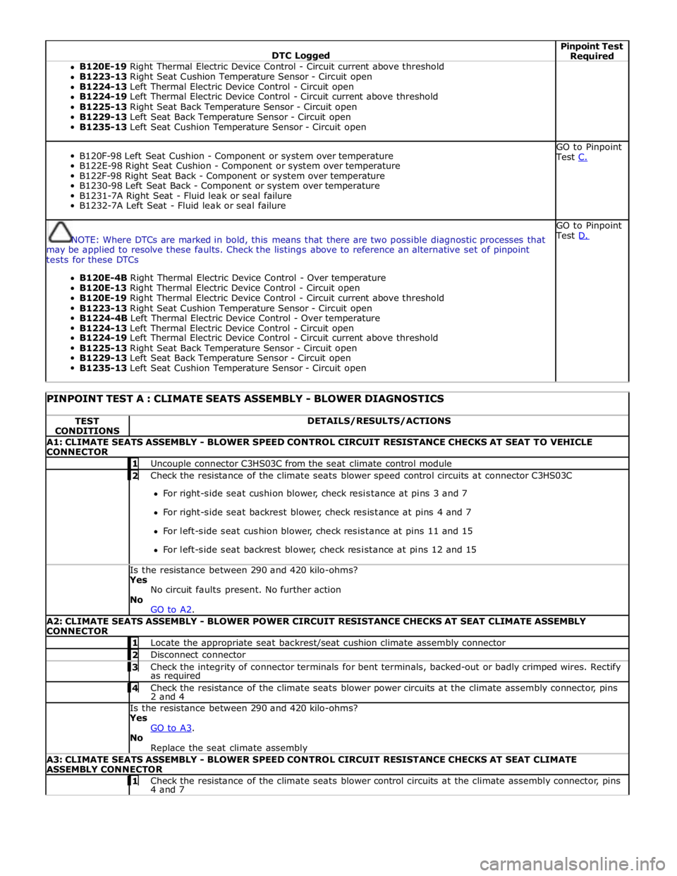
DTC Logged Pinpoint Test Required B120E-19 Right Thermal Electric Device Control - Circuit current above threshold
B1223-13 Right Seat Cushion Temperature Sensor - Circuit open
B1224-13 Left Thermal Electric Device Control - Circuit open
B1224-19 Left Thermal Electric Device Control - Circuit current above threshold
B1225-13 Right Seat Back Temperature Sensor - Circuit open
B1229-13 Left Seat Back Temperature Sensor - Circuit open
B1235-13 Left Seat Cushion Temperature Sensor - Circuit open
B120F-98 Left Seat Cushion - Component or system over temperature
B122E-98 Right Seat Cushion - Component or system over temperature
B122F-98 Right Seat Back - Component or system over temperature
B1230-98 Left Seat Back - Component or system over temperature
B1231-7A Right Seat - Fluid leak or seal failure
B1232-7A Left Seat - Fluid leak or seal failure GO to Pinpoint
Test C.
NOTE: Where DTCs are marked in bold, this means that there are two possible diagnostic processes that
may be applied to resolve these faults. Check the listings above to reference an alternative set of pinpoint
tests for these DTCs
B120E-4B Right Thermal Electric Device Control - Over temperature
B120E-13 Right Thermal Electric Device Control - Circuit open
B120E-19 Right Thermal Electric Device Control - Circuit current above threshold
B1223-13 Right Seat Cushion Temperature Sensor - Circuit open
B1224-4B Left Thermal Electric Device Control - Over temperature
B1224-13 Left Thermal Electric Device Control - Circuit open
B1224-19 Left Thermal Electric Device Control - Circuit current above threshold
B1225-13 Right Seat Back Temperature Sensor - Circuit open
B1229-13 Left Seat Back Temperature Sensor - Circuit open
B1235-13 Left Seat Cushion Temperature Sensor - Circuit open GO to Pinpoint
Test D.
PINPOINT TEST A : CLIMATE SEATS ASSEMBLY - BLOWER DIAGNOSTICS TEST
CONDITIONS DETAILS/RESULTS/ACTIONS A1: CLIMATE SEATS ASSEMBLY - BLOWER SPEED CONTROL CIRCUIT RESISTANCE CHECKS AT SEAT TO VEHICLE
CONNECTOR 1 Uncouple connector C3HS03C from the seat climate control module 2 Check the resistance of the climate seats blower speed control circuits at connector C3HS03C For right-side seat cushion blower, check resistance at pins 3 and 7
For right-side seat backrest blower, check resistance at pins 4 and 7
For left-side seat cushion blower, check resistance at pins 11 and 15
For left-side seat backrest blower, check resistance at pins 12 and 15 Is the resistance between 290 and 420 kilo-ohms? Yes
No circuit faults present. No further action
No
GO to A2. A2: CLIMATE SEATS ASSEMBLY - BLOWER POWER CIRCUIT RESISTANCE CHECKS AT SEAT CLIMATE ASSEMBLY
CONNECTOR 1 Locate the appropriate seat backrest/seat cushion climate assembly connector 2 Disconnect connector 3 Check the integrity of connector terminals for bent terminals, backed-out or badly crimped wires. Rectify as required 4 Check the resistance of the climate seats blower power circuits at the climate assembly connector, pins 2 and 4 Is the resistance between 290 and 420 kilo-ohms? Yes
GO to A3. No
Replace the seat climate assembly A3: CLIMATE SEATS ASSEMBLY - BLOWER SPEED CONTROL CIRCUIT RESISTANCE CHECKS AT SEAT CLIMATE
ASSEMBLY CONNECTOR 1 Check the resistance of the climate seats blower control circuits at the climate assembly connector, pins 4 and 7
Page 2343 of 3039
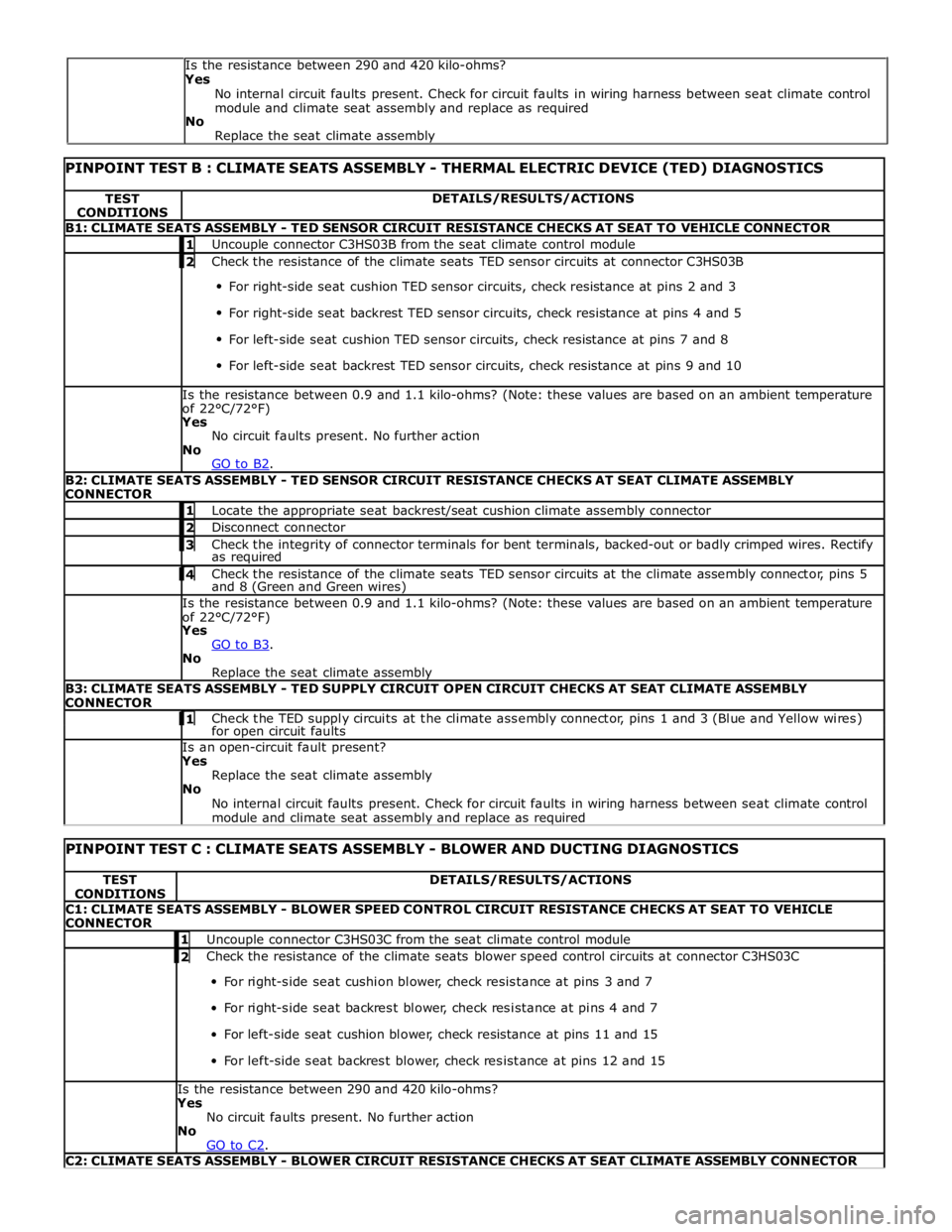
PINPOINT TEST B : CLIMATE SEATS ASSEMBLY - THERMAL ELECTRIC DEVICE (TED) DIAGNOSTICS TEST
CONDITIONS DETAILS/RESULTS/ACTIONS B1: CLIMATE SEATS ASSEMBLY - TED SENSOR CIRCUIT RESISTANCE CHECKS AT SEAT TO VEHICLE CONNECTOR 1 Uncouple connector C3HS03B from the seat climate control module 2 Check the resistance of the climate seats TED sensor circuits at connector C3HS03B For right-side seat cushion TED sensor circuits, check resistance at pins 2 and 3
For right-side seat backrest TED sensor circuits, check resistance at pins 4 and 5
For left-side seat cushion TED sensor circuits, check resistance at pins 7 and 8
For left-side seat backrest TED sensor circuits, check resistance at pins 9 and 10 Is the resistance between 0.9 and 1.1 kilo-ohms? (Note: these values are based on an ambient temperature
of 22°C/72°F) Yes
No circuit faults present. No further action
No
GO to B2. B2: CLIMATE SEATS ASSEMBLY - TED SENSOR CIRCUIT RESISTANCE CHECKS AT SEAT CLIMATE ASSEMBLY
CONNECTOR 1 Locate the appropriate seat backrest/seat cushion climate assembly connector 2 Disconnect connector 3 Check the integrity of connector terminals for bent terminals, backed-out or badly crimped wires. Rectify as required 4 Check the resistance of the climate seats TED sensor circuits at the climate assembly connector, pins 5 and 8 (Green and Green wires) Is the resistance between 0.9 and 1.1 kilo-ohms? (Note: these values are based on an ambient temperature
of 22°C/72°F) Yes
GO to B3. No
Replace the seat climate assembly B3: CLIMATE SEATS ASSEMBLY - TED SUPPLY CIRCUIT OPEN CIRCUIT CHECKS AT SEAT CLIMATE ASSEMBLY
CONNECTOR 1 Check the TED supply circuits at the climate assembly connector, pins 1 and 3 (Blue and Yellow wires) for open circuit faults Is an open-circuit fault present? Yes
Replace the seat climate assembly
No
No internal circuit faults present. Check for circuit faults in wiring harness between seat climate control
module and climate seat assembly and replace as required
PINPOINT TEST C : CLIMATE SEATS ASSEMBLY - BLOWER AND DUCTING DIAGNOSTICS TEST
CONDITIONS DETAILS/RESULTS/ACTIONS C1: CLIMATE SEATS ASSEMBLY - BLOWER SPEED CONTROL CIRCUIT RESISTANCE CHECKS AT SEAT TO VEHICLE
CONNECTOR 1 Uncouple connector C3HS03C from the seat climate control module 2 Check the resistance of the climate seats blower speed control circuits at connector C3HS03C For right-side seat cushion blower, check resistance at pins 3 and 7
For right-side seat backrest blower, check resistance at pins 4 and 7
For left-side seat cushion blower, check resistance at pins 11 and 15
For left-side seat backrest blower, check resistance at pins 12 and 15 Is the resistance between 290 and 420 kilo-ohms?
Yes
No circuit faults present. No further action
No
GO to C2. C2: CLIMATE SEATS ASSEMBLY - BLOWER CIRCUIT RESISTANCE CHECKS AT SEAT CLIMATE ASSEMBLY CONNECTOR Is the resistance between 290 and 420 kilo-ohms?
Yes
No internal circuit faults present. Check for circuit faults in wiring harness between seat climate control
module and climate seat assembly and replace as required
No
Replace the seat climate assembly
Page 2344 of 3039

1 Locate the appropriate seat backrest/seat cushion climate assembly connector 2 Disconnect connector 3 Check the integrity of connector terminals for bent terminals, backed-out or badly crimped wires. Rectify as required 4 Check the resistance of the climate seats blower circuits at the climate assembly connector, pins 2 and 4 (Violet and Black wires) Is the resistance between 290 and 420 kilo-ohms?
Yes
GO to C3. No
Replace the seat climate assembly C3: CLIMATE SEATS ASSEMBLY - BLOWER CONTROL CIRCUIT RESISTANCE CHECKS AT SEAT CLIMATE ASSEMBLY
CONNECTOR 1 Check the resistance of the climate seats blower control circuits at the climate assembly connector, pins 4 and 7 (Black and Purple wires) Is the resistance between 290 and 420 kilo-ohms?
Yes
No internal circuit faults present. Check for circuit faults in wiring harness between seat climate control
module and climate seat assembly and replace as required. If no harness faults are found, GO to C4. No
Replace the seat climate assembly C4: CLIMATE SEATS ASSEMBLY - BLOWER DUCTING INSPECTION 1 Check that the ducting is securely attached to the blower and thermal electric device 2 Check the ducting for holes, cuts or tears Is the ducting undamaged and securely attached to the blower and thermal electric device?
Yes
GO to C5. No
Replace the seat climate assembly C5: CLIMATE SEATS ASSEMBLY - EXHAUST AIRFLOW CHECKS 1 Check for blockages or restrictions at the thermal electric device exhaust vent Are blockages or restrictions present?
Yes
Rectify as required
No
GO to C6. C6: CLIMATE SEATS ASSEMBLY - BLOWER AIRFLOW CHECKS 1 Check for blockages or restrictions at the blower air intake 2 Check that the blower fan movement is not restricted Are there any air intake blockages or restrictions to the blower fan movement?
Yes
Rectify as required
No
No further action
PINPOINT TEST D : CLIMATE SEATS ASSEMBLY - THERMAL ELECTRIC DEVICE (TED) AND DUCTING
DIAGNOSTICS TEST
CONDITIONS DETAILS/RESULTS/ACTIONS D1: CLIMATE SEATS ASSEMBLY - TED SENSOR CIRCUIT RESISTANCE CHECKS AT SEAT TO VEHICLE CONNECTOR 1 Uncouple connector C3HS03B from the seat climate control module 2 Check the resistance of the climate seats TED sensor circuits at connector C3HS03B For right-side seat cushion TED sensor circuits, check resistance at pins 2 and 3
For right-side seat backrest TED sensor circuits, check resistance at pins 4 and 5
For left-side seat cushion TED sensor circuits, check resistance at pins 7 and 8
For left-side seat backrest TED sensor circuits, check resistance at pins 9 and 10 Is the resistance between 0.9 and 1.1 kilo-ohms? (Note: these values are based on an ambient temperature
of 22°C/72°F)
Yes
No circuit faults present. No further action
No
GO to D2. D2: CLIMATE SEATS ASSEMBLY - TED SENSOR CIRCUIT RESISTANCE CHECKS AT SEAT CLIMATE ASSEMBLY
CONNECTOR 1 Locate the appropriate seat backrest/seat cushion climate assembly connector 2 Disconnect connector 3 Check the integrity of connector terminals for bent terminals, backed-out or badly crimped wires. Rectify as required www.JagDocs.com