2010 JAGUAR XFR Module
[x] Cancel search: ModulePage 2903 of 3039
and Installation).
5. Disconnect the generator electrical connectors.
6. Remove the right-hand and left-hand front scuff plate trim panels.
For additional information, refer to: Front Scuff Plate Trim Panel (501-05 Interior Trim and Ornamentation, Removal and Installation).
7. Remove the front and rear door weatherstrips.
8. Remove the right-hand and left-hand rear scuff plate trim panels.
For additional information, refer to: Rear Scuff Plate Trim Panel (501-05 Interior Trim and Ornamentation, Removal and Installation).
9. Remove the headliner.
For additional information, refer to: Headliner (501-05 Interior Trim and Ornamentation, Removal and Installation).
10. Remove the side air curtain module.
For additional information, refer to: Side Air Curtain Module (501-20B Supplemental Restraint System, Removal and Installation).
11. Remove the rear seat cushion.
For additional information, refer to: Rear Seat Cushion (501-10 Seating, Removal and Installation).
12. Remove the rear seat backrest.
13. Release and position the roof wiring harness to one side.
14. Remove the roof moulding.
15. Remove the cowl side trim panel.
For additional information, refer to: Cowl Side Trim Panel (501-05 Interior Trim and Ornamentation, Removal and Installation).
16. Remove the front safety belt retractor.
For additional information, refer to: Front Safety Belt Retractor (501-20A Safety Belt System, Removal and Installation).
17. Remove the B-pillar side impact sensor.
For additional information, refer to: B-Pillar Side Impact Sensor (501-20B Supplemental Restraint System, Removal and Installation).
18. Remove the C-pillar side impact sensor.
For additional information, refer to: C-Pillar Side Impact Sensor (501-20B Supplemental Restraint System, Removal and Installation).
19. Release and position the floor covering to one side.
20. Release and position the inner rocker panel wiring harness to one side.
21. Remove the rear wheel and tire.
For additional information, refer to: Wheel and Tire (204-04 Wheels and
Page 2943 of 3039
Rear End Sheet Metal Repairs - Back Panel
Removal and Installation
Removal Published: 11-May-2011
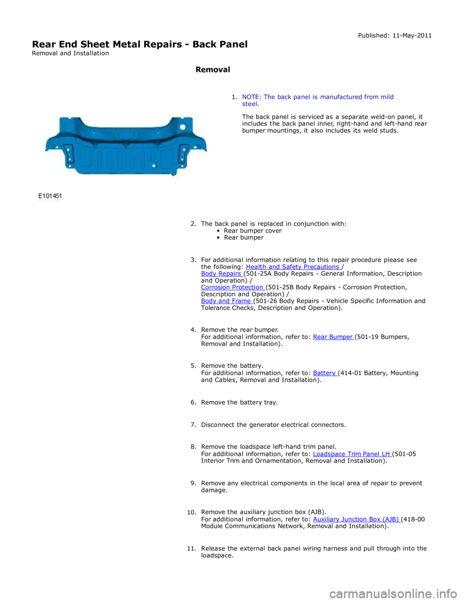
1. NOTE: The back panel is manufactured from mild
steel.
The back panel is serviced as a separate weld-on panel, it
includes the back panel inner, right-hand and left-hand rear
bumper mountings, it also includes its weld studs.
2. The back panel is replaced in conjunction with:
Rear bumper cover
Rear bumper
3. For additional information relating to this repair procedure please see
the following: Health and Safety Precautions / Body Repairs (501-25A Body Repairs - General Information, Description and Operation) /
Corrosion Protection (501-25B Body Repairs - Corrosion Protection, Description and Operation) /
Body and Frame (501-26 Body Repairs - Vehicle Specific Information and Tolerance Checks, Description and Operation).
4. Remove the rear bumper.
For additional information, refer to: Rear Bumper (501-19 Bumpers, Removal and Installation).
5. Remove the battery.
For additional information, refer to: Battery (414-01 Battery, Mounting and Cables, Removal and Installation).
6. Remove the battery tray.
7. Disconnect the generator electrical connectors.
8. Remove the loadspace left-hand trim panel.
For additional information, refer to: Loadspace Trim Panel LH (501-05 Interior Trim and Ornamentation, Removal and Installation).
9. Remove any electrical components in the local area of repair to prevent
damage.
10. Remove the auxiliary junction box (AJB).
For additional information, refer to: Auxiliary Junction Box (AJB) (418-00 Module Communications Network, Removal and Installation).
11. Release the external back panel wiring harness and pull through into the
loadspace.
Page 2949 of 3039
Removal and Installation).
7. Remove the battery.
For additional information, refer to: Battery (414-01 Battery, Mounting and Cables, Removal and Installation).
8. Disconnect the generator electrical connectors.
9. If the left-hand rear quarter panel is to be repaired, remove the
loadspace left-hand trim panel.
For additional information, refer to: Loadspace Trim Panel LH (501-05 Interior Trim and Ornamentation, Removal and Installation).
10. If the right-hand rear quarter panel is to be repaired, remove the
auxiliary junction box (AJB).
For additional information, refer to: Auxiliary Junction Box (AJB) (418-00 Module Communications Network, Removal and Installation).
11. Remove any electrical components in the local area of repair to prevent
damage.
12. Remove the rear muffler.
For additional information, refer to: Rear Muffler (309-00C Exhaust System - V8 5.0L Petrol/V8 S/C 5.0L Petrol, Removal and Installation) /
Rear Muffler (309-00C Exhaust System - V8 5.0L Petrol/V8 S/C 5.0L Petrol, Removal and Installation) /
Rear Muffler (309-00C Exhaust System - V8 5.0L Petrol/V8 S/C 5.0L Petrol, Removal and Installation).
13. Remove the exhaust muffler and tailpipe heatshield.
14. Remove the rear scuff plate trim panel.
For additional information, refer to: Rear Scuff Plate Trim Panel (501-05 Interior Trim and Ornamentation, Removal and Installation).
15. Remove the loadspace trim panel.
For additional information, refer to: Loadspace Trim Panel (501-05 Interior Trim and Ornamentation, Removal and Installation).
16. Remove the forced air extraction grille.
17. Release and lay aside the back panel and loadspace wiring harness.
18. Remove the luggage compartment lid weatherstrip.
19. Remove the rear bumper cover side retainer.
20. Remove the roof moulding.
21. Remove the headliner.
For additional information, refer to: Headliner (501-05 Interior Trim and Ornamentation, Removal and Installation).
22. Remove the side air curtain module.
www.JagDocs.com
Page 2950 of 3039
Supplemental Restraint System, Removal and Installation).
23. Remove the rear window glass.
24. Remove the audio unit antenna amplifier.
For additional information, refer to: Audio Unit Antenna Amplifier (415-01A Information and Entertainment System, Removal and
Installation).
25. If the left-hand rear quarter panel is to be repaired, remove the diversity
antenna module.
26. Remove the C-Pillar side impact sensor.
For additional information, refer to: C-Pillar Side Impact Sensor (501-20B Supplemental Restraint System, Removal and Installation).
27. Remove the rear door striker.
28. Remove the luggage compartment lid.
29. If the right-hand rear quarter panel is to be repaired, drain the fuel tank.
For additional information, refer to: Fuel Tank Draining (310-00 Fuel System - General Information, General Procedures).
30. If the right-hand rear quarter panel is to be repaired, remove the fuel
filler door.
31. If the right-hand rear quarter panel is to be repaired, remove the fuel
tank filler pipe.
For additional information, refer to: Fuel Tank Filler Pipe (310-01 Fuel
Tank and Lines - 3.0L, Removal and Installation) /
Fuel Tank Filler Pipe (310-01 Fuel Tank and Lines - 4.2L, Removal and
Installation).
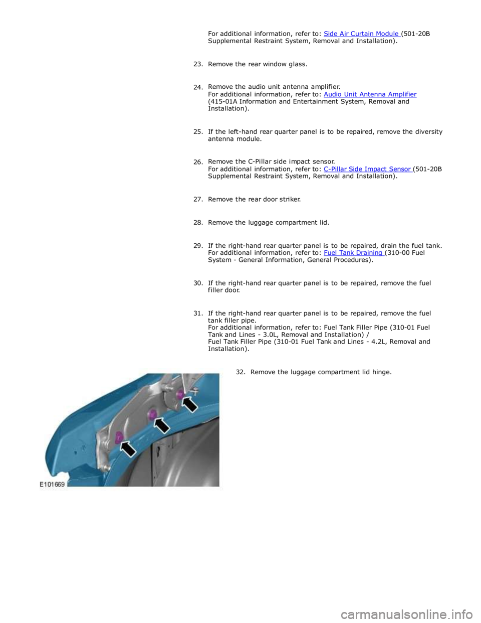
32. Remove the luggage compartment lid hinge.
Page 2964 of 3039
Rear End Sheet Metal Repairs - Rear Bumper Mounting
Removal and Installation
Removal Published: 11-May-2011
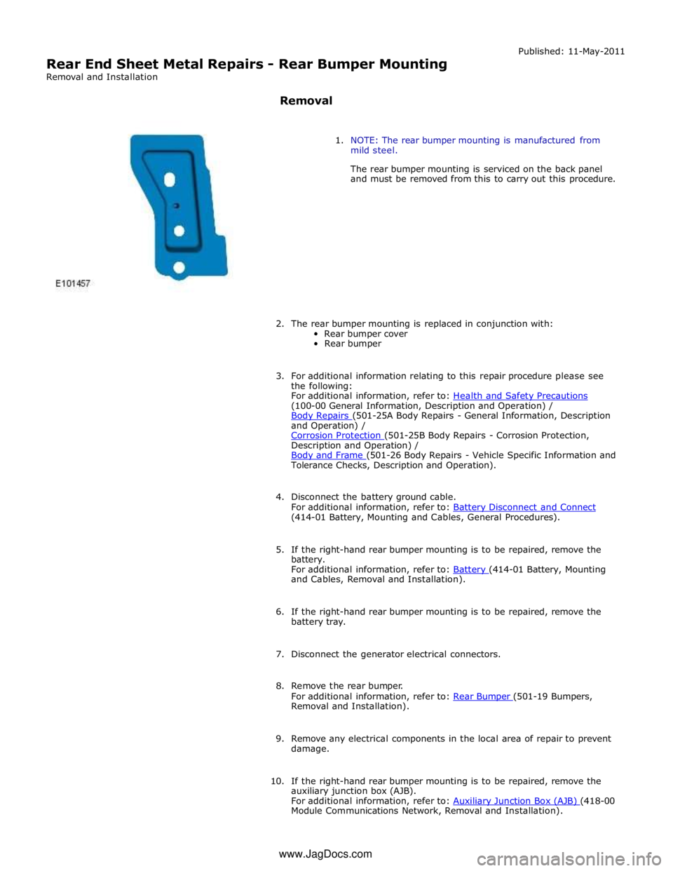
1. NOTE: The rear bumper mounting is manufactured from
mild steel.
The rear bumper mounting is serviced on the back panel
and must be removed from this to carry out this procedure.
2. The rear bumper mounting is replaced in conjunction with:
Rear bumper cover
Rear bumper
3. For additional information relating to this repair procedure please see
the following:
For additional information, refer to: Health and Safety Precautions (100-00 General Information, Description and Operation) /
Body Repairs (501-25A Body Repairs - General Information, Description and Operation) /
Corrosion Protection (501-25B Body Repairs - Corrosion Protection, Description and Operation) /
Body and Frame (501-26 Body Repairs - Vehicle Specific Information and Tolerance Checks, Description and Operation).
4. Disconnect the battery ground cable.
For additional information, refer to: Battery Disconnect and Connect (414-01 Battery, Mounting and Cables, General Procedures).
5. If the right-hand rear bumper mounting is to be repaired, remove the
battery.
For additional information, refer to: Battery (414-01 Battery, Mounting and Cables, Removal and Installation).
6. If the right-hand rear bumper mounting is to be repaired, remove the
battery tray.
7. Disconnect the generator electrical connectors.
8. Remove the rear bumper.
For additional information, refer to: Rear Bumper (501-19 Bumpers, Removal and Installation).
9. Remove any electrical components in the local area of repair to prevent
damage.
10. If the right-hand rear bumper mounting is to be repaired, remove the
auxiliary junction box (AJB).
For additional information, refer to: Auxiliary Junction Box (AJB) (418-00 Module Communications Network, Removal and Installation). www.JagDocs.com
Page 2982 of 3039
12.
13.
14.
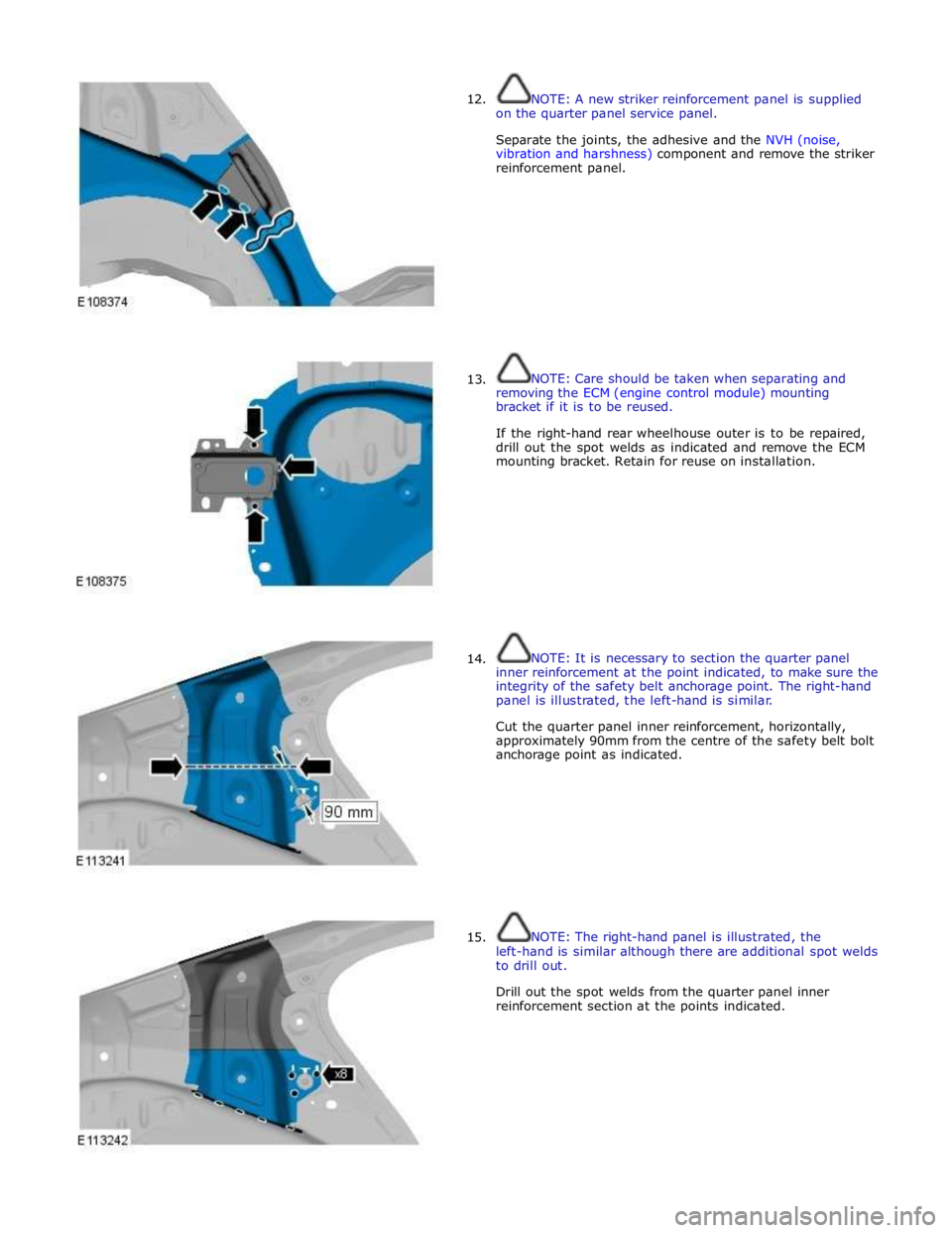
15. NOTE: A new striker reinforcement panel is supplied
on the quarter panel service panel.
Separate the joints, the adhesive and the NVH (noise,
vibration and harshness) component and remove the striker
reinforcement panel.
NOTE: Care should be taken when separating and
removing the ECM (engine control module) mounting
bracket if it is to be reused.
If the right-hand rear wheelhouse outer is to be repaired,
drill out the spot welds as indicated and remove the ECM
mounting bracket. Retain for reuse on installation.
NOTE: It is necessary to section the quarter panel
inner reinforcement at the point indicated, to make sure the
integrity of the safety belt anchorage point. The right-hand
panel is illustrated, the left-hand is similar.
Cut the quarter panel inner reinforcement, horizontally,
approximately 90mm from the centre of the safety belt bolt
anchorage point as indicated.
NOTE: The right-hand panel is illustrated, the
left-hand is similar although there are additional spot welds
to drill out.
Drill out the spot welds from the quarter panel inner
reinforcement section at the points indicated.