2010 JAGUAR XFR radio
[x] Cancel search: radioPage 2140 of 3039
Published: 11-May-2011
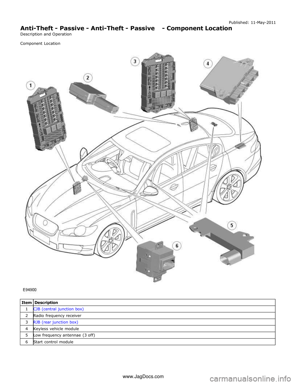
Anti-Theft - Passive - Anti-Theft - Passive - Component Location
Description and Operation
Component Location
Item Description 1 CJB (central junction box) 2 Radio frequency receiver 3 RJB (rear junction box) 4 Keyless vehicle module 5 Low frequency antennae (3 off) 6 Start control module www.JagDocs.com
Page 2143 of 3039
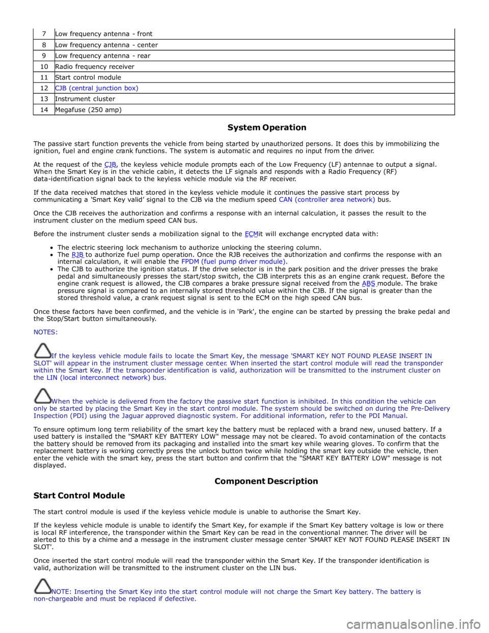
7 Low frequency antenna - front 8 Low frequency antenna - center 9 Low frequency antenna - rear 10 Radio frequency receiver 11 Start control module 12 CJB (central junction box) 13 Instrument cluster 14 Megafuse (250 amp)
System Operation
The passive start function prevents the vehicle from being started by unauthorized persons. It does this by immobilizing the
ignition, fuel and engine crank functions. The system is automatic and requires no input from the driver.
At the request of the CJB, the keyless vehicle module prompts each of the Low Frequency (LF) antennae to output a signal. When the Smart Key is in the vehicle cabin, it detects the LF signals and responds with a Radio Frequency (RF)
data-identification signal back to the keyless vehicle module via the RF receiver.
If the data received matches that stored in the keyless vehicle module it continues the passive start process by
communicating a 'Smart Key valid’ signal to the CJB via the medium speed CAN (controller area network) bus.
Once the CJB receives the authorization and confirms a response with an internal calculation, it passes the result to the
instrument cluster on the medium speed CAN bus.
Before the instrument cluster sends a mobilization signal to the ECMit will exchange encrypted data with: The electric steering lock mechanism to authorize unlocking the steering column.
The RJB to authorize fuel pump operation. Once the RJB receives the authorization and confirms the response with an internal calculation, it will enable the FPDM (fuel pump driver module).
The CJB to authorize the ignition status. If the drive selector is in the park position and the driver presses the brake
pedal and simultaneously presses the start/stop switch, the CJB interprets this as an engine crank request. Before the
engine crank request is allowed, the CJB compares a brake pressure signal received from the ABS module. The brake pressure signal is compared to an internally stored threshold value within the CJB. If the signal is greater than the
stored threshold value, a crank request signal is sent to the ECM on the high speed CAN bus.
Once these factors have been confirmed, and the vehicle is in 'Park', the engine can be started by pressing the brake pedal and
the Stop/Start button simultaneously.
NOTES:
If the keyless vehicle module fails to locate the Smart Key, the message 'SMART KEY NOT FOUND PLEASE INSERT IN
SLOT' will appear in the instrument cluster message center. When inserted the start control module will read the transponder
within the Smart Key. If the transponder identification is valid, authorization will be transmitted to the instrument cluster on
the LIN (local interconnect network) bus.
When the vehicle is delivered from the factory the passive start function is inhibited. In this condition the vehicle can
only be started by placing the Smart Key in the start control module. The system should be switched on during the Pre-Delivery
Inspection (PDI) using the Jaguar approved diagnostic system. For additional information, refer to the PDI Manual.
To ensure optimum long term reliability of the smart key the battery must be replaced with a brand new, unused battery. If a
used battery is installed the "SMART KEY BATTERY LOW" message may not be cleared. To avoid contamination of the contacts
the battery should be removed from its packaging and installed into the smart key while wearing gloves. To confirm that the
replacement battery is working correctly press the unlock button twice while holding the smart key outside the vehicle, then
enter the vehicle with the smart key, press the start button and confirm that the "SMART KEY BATTERY LOW" message is not
displayed.
Start Control Module Component Description
The start control module is used if the keyless vehicle module is unable to authorise the Smart Key.
If the keyless vehicle module is unable to identify the Smart Key, for example if the Smart Key battery voltage is low or there
is local RF interference, the transponder within the Smart Key can be read in the conventional manner. The driver will be
alerted to this by a chime and a message in the instrument cluster message center 'SMART KEY NOT FOUND PLEASE INSERT IN
SLOT'.
Once inserted the start control module will read the transponder within the Smart Key. If the transponder identification is
valid, authorization will be transmitted to the instrument cluster on the LIN bus.
NOTE: Inserting the Smart Key into the start control module will not charge the Smart Key battery. The battery is
non-chargeable and must be replaced if defective.
Page 2144 of 3039

A message 'REMOVE SMART KEY' will be displayed if the Smart Key is still in the start control module and the driver's door is
opened.
Low Frequency Antenna
Three Low Frequency (LF) antennae for the passive start system are positioned in specific locations in the vehicle; refer to
Component Location graphic.
NOTE: On vehicles with the passive entry system, five additional antennae are used; one integrated into the rear bumper
and one in each door handle assembly. These are only used by the passive entry system and have no function in the passive
start system.
The keyless vehicle module transmits an LF signal via the antennae which is received by the Smart Key. The Smart Key then
responds by transmitting a Radio Frequency (RF) signal which is received by the RF receiver and passed to the keyless vehicle
module for authorization.
Keyless Vehicle Module
The keyless vehicle module controls signal transmissions to and from the Smart Key and provides authorization to allow the
vehicle to be started. The module has a medium speed CAN connection to the CJB for authorizing vehicle starting.
Radio Frequency Receiver
The Radio Frequency (RF) receiver transmission is received from the Smart Key to enable key identification.
Page 2167 of 3039
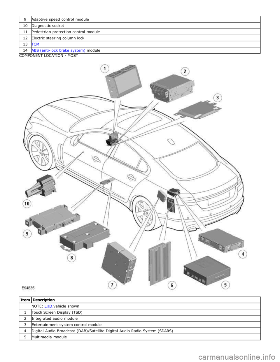
10 Diagnostic socket 11 Pedestrian protection control module 12 Electric steering column lock 13 TCM 14 ABS (anti-lock brake system) module COMPONENT LOCATION - MOST
Item Description NOTE: LHD vehicle shown 1 Touch Screen Display (TSD) 2 Integrated audio module 3 Entertainment system control module 4 Digital Audio Broadcast (DAB)/Satellite Digital Audio Radio System (SDARS) 5 Multimedia module
Page 2172 of 3039
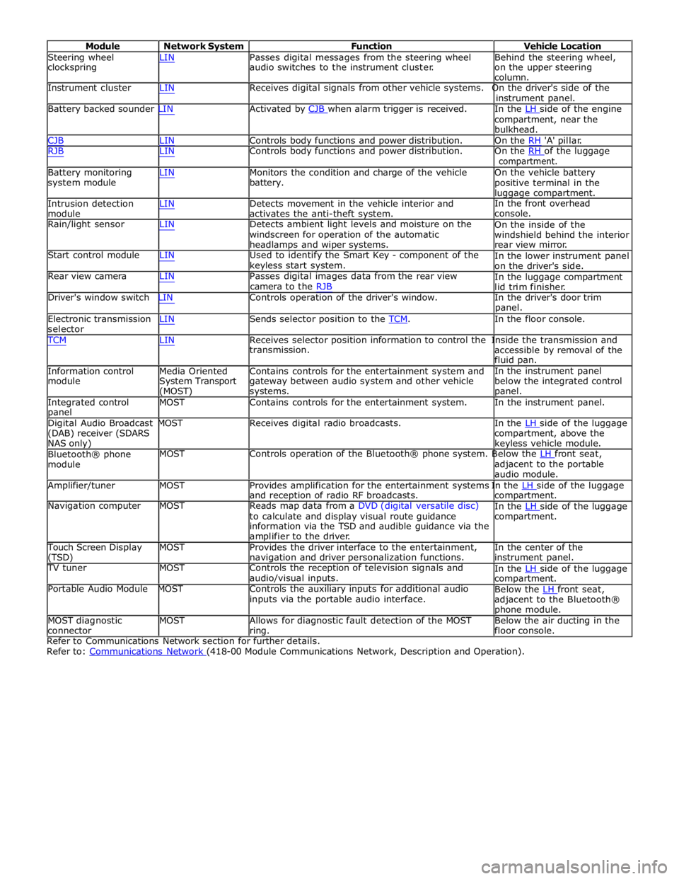
Module Network System Function Vehicle Location
Steering wheel
clockspring LIN Passes digital messages from the steering wheel
audio switches to the instrument cluster. Behind the steering wheel,
on the upper steering
column.
Instrument cluster LIN Receives digital signals from other vehicle systems. On the driver's side of the
instrument panel.
Battery backed sounder LIN Activated by CJB when alarm trigger is received. In the LH side of the engine compartment, near the
bulkhead.
CJB LIN Controls body functions and power distribution. On the RH 'A' pillar.
RJB LIN Controls body functions and power distribution. On the RH of the luggage compartment.
Battery monitoring
system module
Intrusion detection
module LIN Monitors the condition and charge of the vehicle
battery.
LIN Detects movement in the vehicle interior and
activates the anti-theft system. On the vehicle battery
positive terminal in the
luggage compartment.
In the front overhead
console.
Rain/light sensor LIN Detects ambient light levels and moisture on the
windscreen for operation of the automatic
headlamps and wiper systems.
Start control module LIN Used to identify the Smart Key - component of the
keyless start system.
Rear view camera LIN Passes digital images data from the rear view
camera to the RJB On the inside of the
windshield behind the interior
rear view mirror.
In the lower instrument panel
on the driver's side.
In the luggage compartment
lid trim finisher.
Driver's window switch LIN Controls operation of the driver's window. In the driver's door trim
panel.
Electronic transmission
selector LIN Sends selector position to the TCM. In the floor console. TCM LIN Receives selector position information to control the Inside the transmission and
Information control
module
Media Oriented
System Transport
(MOST) transmission.
Contains controls for the entertainment system and
gateway between audio system and other vehicle
systems. accessible by removal of the
fluid pan.
In the instrument panel
below the integrated control
panel.
Integrated control
panel MOST Contains controls for the entertainment system. In the instrument panel.
Digital Audio Broadcast MOST Receives digital radio broadcasts. In the LH side of the luggage (DAB) receiver (SDARS
NAS only)
Bluetooth® phone
module compartment, above the
keyless vehicle module.
MOST Controls operation of the Bluetooth® phone system. Below the LH front seat, adjacent to the portable
audio module.
Amplifier/tuner MOST Provides amplification for the entertainment systems In the LH side of the luggage and reception of radio RF broadcasts.
Navigation computer MOST Reads map data from a DVD (digital versatile disc)
to calculate and display visual route guidance
information via the TSD and audible guidance via the
amplifier to the driver. compartment.
In the LH side of the luggage compartment.
Touch Screen Display
(TSD) MOST Provides the driver interface to the entertainment,
navigation and driver personalization functions. In the center of the
instrument panel.
TV tuner MOST Controls the reception of television signals and
audio/visual inputs.
Portable Audio Module MOST Controls the auxiliary inputs for additional audio
inputs via the portable audio interface. In the LH side of the luggage compartment.
Below the LH front seat, adjacent to the Bluetooth®
phone module.
MOST diagnostic
connector MOST Allows for diagnostic fault detection of the MOST
ring. Below the air ducting in the
floor console.
Refer to Communications Network section for further details.
Refer to: Communications Network (418-00 Module Communications Network, Description and Operation).
Page 2376 of 3039
Seating - Seat Base
Removal and Installation
Removal
WARNINGS: Published: 11-May-2011
To avoid accidental deployment, the restraints control module backup power supply must be depleted. Wait at least one
minute after disconnecting the battery ground cable(s) before commencing any repair or adjustment to the supplemental
restraint system (SRS), or any component(s) adjacent to the SRS sensors. Failure to follow these instructions may result in
personal injury.
Always wear safety glasses when working on an air bag equipped vehicle and when handling an air bag module. Failure to
follow this instruction may result in personal injury.
To minimize the possibility of premature deployment, do not use radio key code savers when working on the
supplemental restraint system. Failure to follow this instruction may result in personal injury.
To minimize the possibility of injury in the event of premature deployment, always carry a live air bag module with the
bag and trim cover pointed away from the body. Failure to follow this instruction may result in personal injury.
To minimize the possibility of premature deployment, live air bag modules must only be placed on work benches which
have been ground bonded and with the trim cover facing up. Failure to follow these instructions may result in personal injury.
Never probe the electrical connectors of air bag modules or any other supplemental restraint system component. Failure
to follow this instruction may result in personal injury.
Painting over the driver air bag module trim cover or instrument panel could lead to deterioration of the trim cover and air
bags. Do not for any reason attempt to paint discolored or damaged air bag module trim covers or instrument panel. Install a
new component. Failure to follow this instruction may result in personal injury.
NOTES:
Some variation in the illustrations may occur, but the essential information is always correct.
Removal steps in this procedure may contain installation details.
1. Make the air bag supplemental restraint system (SRS) safe.
Refer to: Standard Workshop Practices (100-00 General Information, Description and Operation).
2. Refer to: Front Seat (501-10 Seating, Removal and Installation).
3. Refer to: Front Safety Belt Buckle (501-20A Safety Belt System, Removal and Installation).
4. Refer to: Front Seat Cushion Cover (501-10 Seating, Removal and Installation).
Page 2488 of 3039
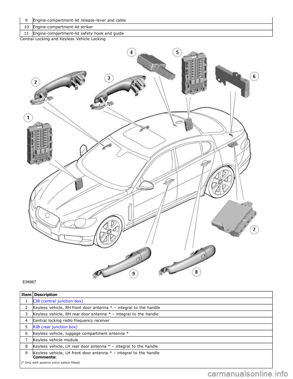
10 Engine-compartment-lid striker 11 Engine-compartment-lid safety hook and guide Central Locking and Keyless Vehicle Locking
Item Description 1 CJB (central junction box) 2 Keyless vehicle, RH front door antenna * – integral to the handle 3 Keyless vehicle, RH rear door antenna * – integral to the handle 4 Central locking radio frequency receiver 5 RJB (rear junction box) 6 Keyless vehicle, luggage compartment antenna * 7 Keyless vehicle module 8 Keyless vehicle, LH rear door antenna * – integral to the handle 9 Keyless vehicle, LH front door antenna * – integral to the handle Comments:
(* Only with passive entry option fitted)
Page 2491 of 3039
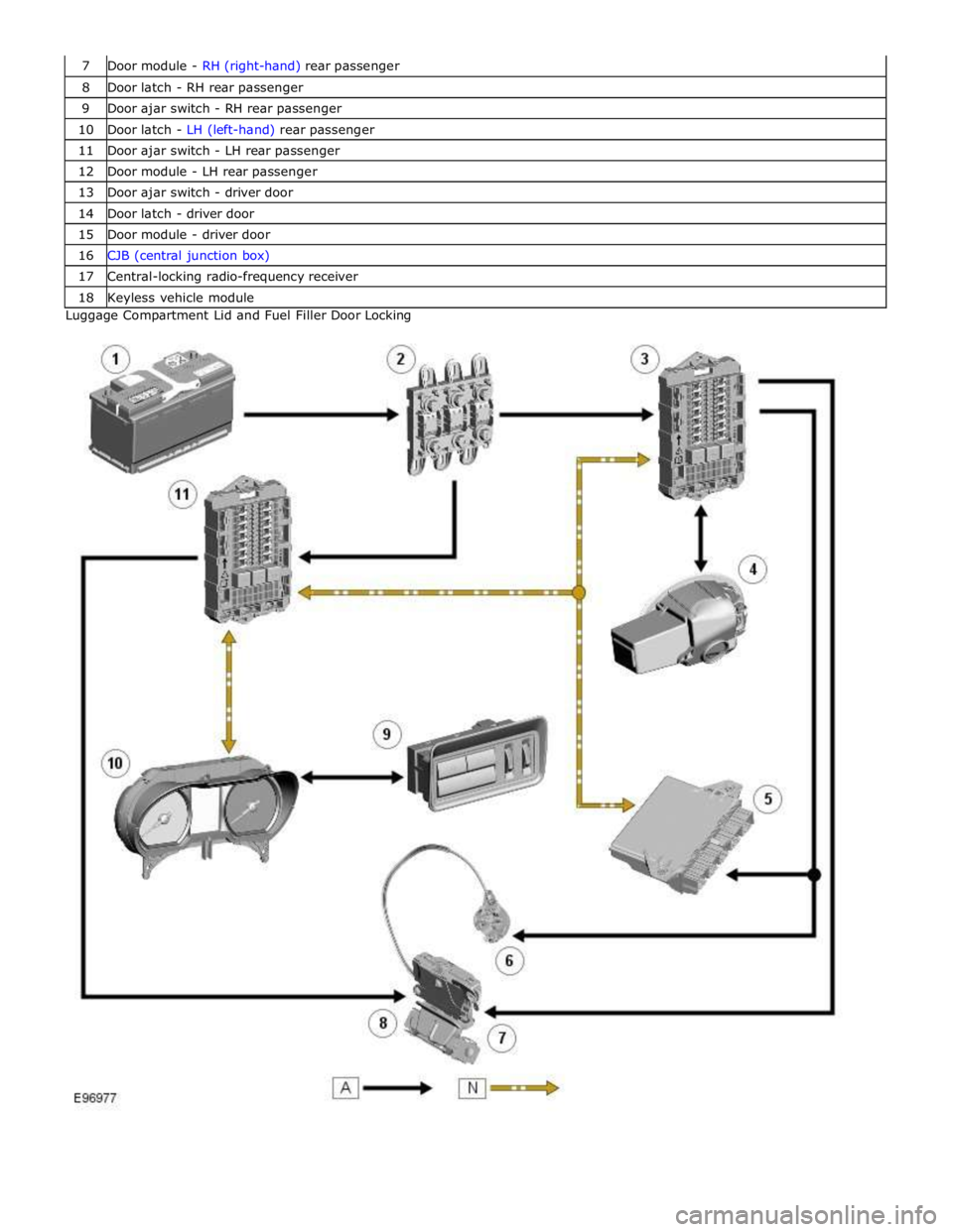
8 Door latch - RH rear passenger 9 Door ajar switch - RH rear passenger 10 Door latch - LH (left-hand) rear passenger 11 Door ajar switch - LH rear passenger 12 Door module - LH rear passenger 13 Door ajar switch - driver door 14 Door latch - driver door 15 Door module - driver door 16 CJB (central junction box) 17 Central-locking radio-frequency receiver 18 Keyless vehicle module Luggage Compartment Lid and Fuel Filler Door Locking