2010 JAGUAR XFR radio
[x] Cancel search: radioPage 1953 of 3039
7 Triple TV antenna module 8 RF filter The diversity antenna module, located on the left hand side of the heated rear window, receives signals from four antennas
located in the heated rear window, where one antenna is dedicated as an AM antenna.
The diversity tuning system ensures that the strongest signals are used by the radio system to ensure the best possible FM
reception. Using the three remaining receiving antennas serves to eliminate multipath signal distortion. Typically, the signal
from the antenna with the least noise is chosen, and the other antennas are ignored.
The diversity antenna module is an interface between the antenna aerials in the heated rear window and audio system
modules/tuners. It provides antenna signals to the AM/FM tuner in the IAM, to the DAB receiver and to the VICS (vehicle
information and communication systems) or TMC (traffic message channel) in the navigation computer.
There are three different types of diversity antenna module fitted depending on the vehicle market and infotainment
equipment specification:
AM/FM with one co-axial output
AM/FM and VICS/TMC with two co-axial outputs
AM/FM, VICS/TMC and DAB band III with three co-axial outputs
The diversity antenna module receives a power supply from the IAM.
Vehicle or other component generated electromagnetic interference may cause unwanted disturbances in the radio and TV
reception signals. The disturbance may interrupt, obstruct, or otherwise degrade or limit the effective performance of the
circuit. It frequently affects the reception of AM radio in urban areas and can also affect FM radio and television reception,
although to a lesser extent.
The RF filters, which act as RF isolators, are located on both sides of the heated rear window and are used to reduce the
electromagnetic interference. The left hand side RF filter is connected across the heated rear window power supply and used to
separate the DC (direct current) interference from the RF signals. The right hand side RF filter is used in conjunction with the
TV antenna module (if fitted). If the TV system is not fitted the filter is linked directly to ground.
INFORMATION CONTROL MODULE
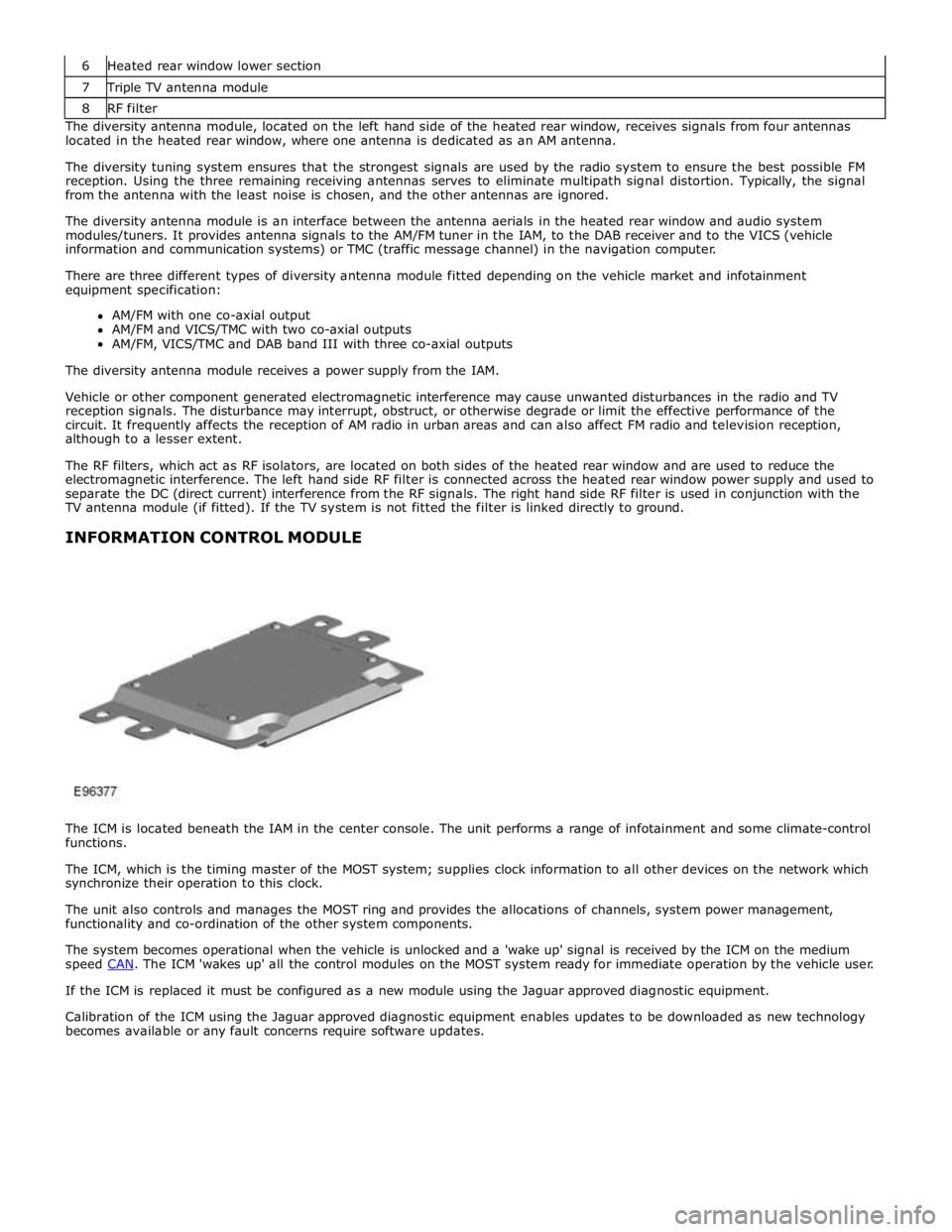
The ICM is located beneath the IAM in the center console. The unit performs a range of infotainment and some climate-control
functions.
The ICM, which is the timing master of the MOST system; supplies clock information to all other devices on the network which
synchronize their operation to this clock.
The unit also controls and manages the MOST ring and provides the allocations of channels, system power management,
functionality and co-ordination of the other system components.
The system becomes operational when the vehicle is unlocked and a 'wake up' signal is received by the ICM on the medium
speed CAN. The ICM 'wakes up' all the control modules on the MOST system ready for immediate operation by the vehicle user. If the ICM is replaced it must be configured as a new module using the Jaguar approved diagnostic equipment.
Calibration of the ICM using the Jaguar approved diagnostic equipment enables updates to be downloaded as new technology
becomes available or any fault concerns require software updates.
Page 1956 of 3039
controlled through the device itself.
NOTE: The system will support devices with a storage capacity up to 256 GB which is approximately 65,000 audio tracks.
The wiring link harness between the portable audio module and interface panel consists of hardwired and digital connections
for data and signal exchange. The MOST carries the communication signals and information between the portable audio module
to the IAM and touch-screen. Audio output to the speaker system is controlled by the IAM or power amplifier depending on the
audio system specification.
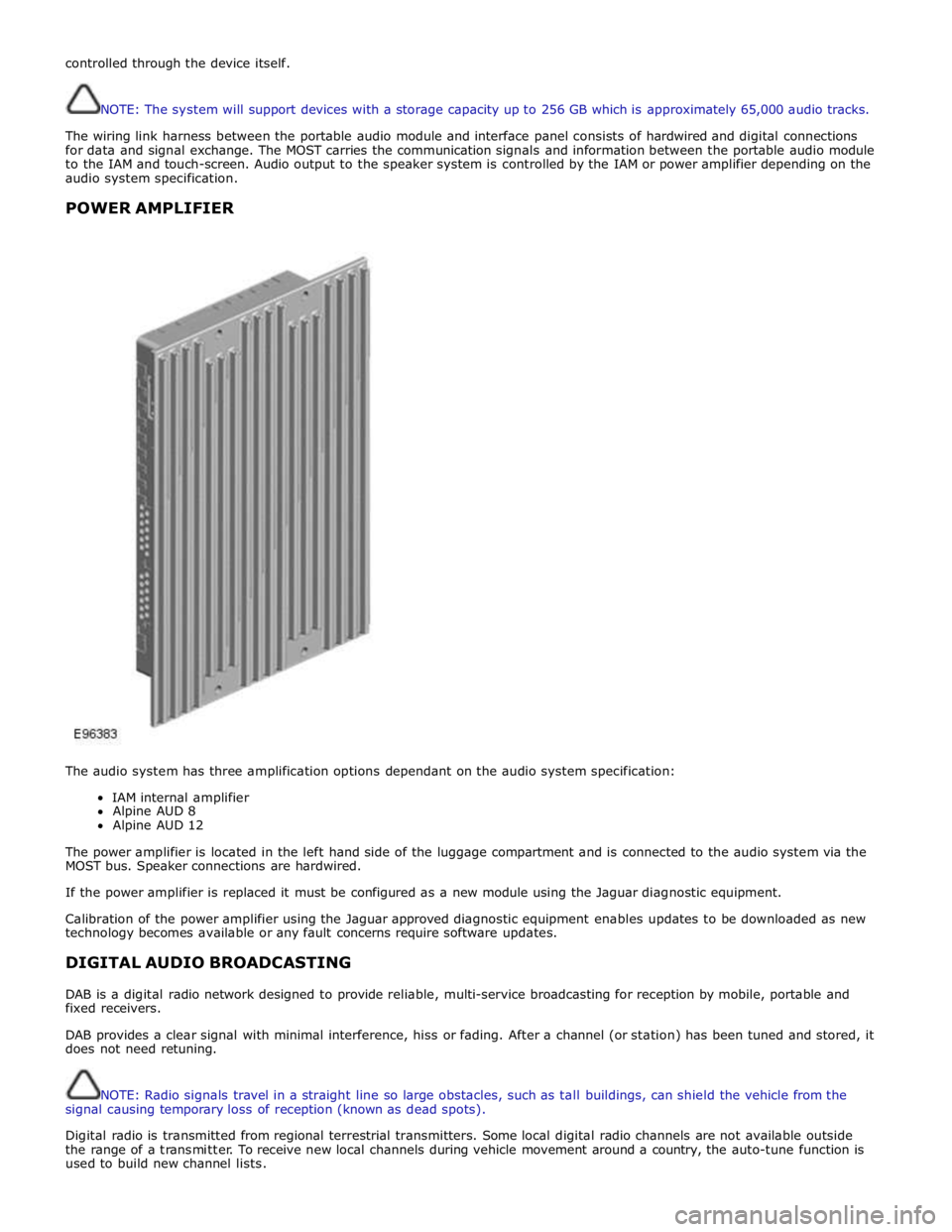
POWER AMPLIFIER
The audio system has three amplification options dependant on the audio system specification:
IAM internal amplifier
Alpine AUD 8
Alpine AUD 12
The power amplifier is located in the left hand side of the luggage compartment and is connected to the audio system via the
MOST bus. Speaker connections are hardwired.
If the power amplifier is replaced it must be configured as a new module using the Jaguar diagnostic equipment.
Calibration of the power amplifier using the Jaguar approved diagnostic equipment enables updates to be downloaded as new
technology becomes available or any fault concerns require software updates.
DIGITAL AUDIO BROADCASTING
DAB is a digital radio network designed to provide reliable, multi-service broadcasting for reception by mobile, portable and
fixed receivers.
DAB provides a clear signal with minimal interference, hiss or fading. After a channel (or station) has been tuned and stored, it
does not need retuning.
NOTE: Radio signals travel in a straight line so large obstacles, such as tall buildings, can shield the vehicle from the
signal causing temporary loss of reception (known as dead spots).
Digital radio is transmitted from regional terrestrial transmitters. Some local digital radio channels are not available outside
the range of a transmitter. To receive new local channels during vehicle movement around a country, the auto-tune function is
used to build new channel lists.
Page 1957 of 3039
NOTE: When the vehicle DAB radio is first used the system will not receive any digital stations until the auto-tune
function has been completed.
Digital radio channels are organized into groups called ensembles (also known as multiplexes). Some individual channels may
also provide a number of subchannels. For example, if several sports events are being held simultaneously, the channel may
temporarily choose to broadcast each different event on a separate subchannel.
DAB is broadcast across Europe, Canada and parts of Asia. System transmission is via a terrestrial network, on two separate
broadcasting bands:
DAB band-L
DAB band III
The DAB system requires additional components to be added to the audio system. DAB antennas and a receiver are fitted to
allow reception of the service.
Operation of the DAB system is the same as the radio operation with selections made through the touch-screen and ICP to
access and navigate the system functions.
The DAB receiver is a dedicated tuner which is controlled by the ICM on the MOST ring. The receiver processes the signals from
the DAB antennas. Information is transmitted on the MOST ring and processed by the ICM. The processed information is sent
out to the power amplifier or IAM (with internal amplifier) and broadcast through the speaker system.
No configuration procedure is required if the DAB receiver is replaced. Calibration of the DAB receiver using the Jaguar
approved diagnostic equipment enables updates to be downloaded as new technology becomes available or any fault concerns
require software updates.
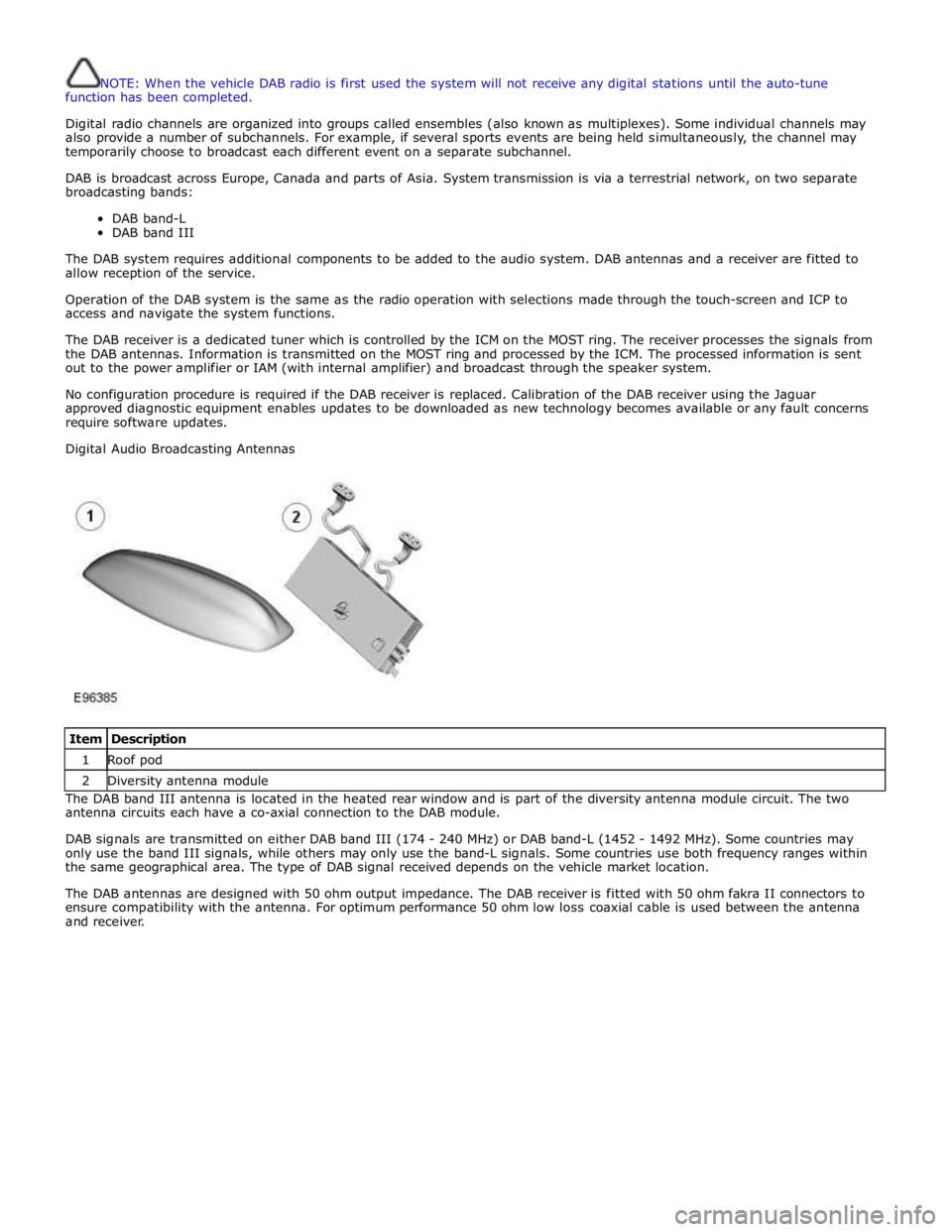
Digital Audio Broadcasting Antennas
Item Description 1 Roof pod 2 Diversity antenna module The DAB band III antenna is located in the heated rear window and is part of the diversity antenna module circuit. The two
antenna circuits each have a co-axial connection to the DAB module.
DAB signals are transmitted on either DAB band III (174 - 240 MHz) or DAB band-L (1452 - 1492 MHz). Some countries may
only use the band III signals, while others may only use the band-L signals. Some countries use both frequency ranges within
the same geographical area. The type of DAB signal received depends on the vehicle market location.
The DAB antennas are designed with 50 ohm output impedance. The DAB receiver is fitted with 50 ohm fakra II connectors to
ensure compatibility with the antenna. For optimum performance 50 ohm low loss coaxial cable is used between the antenna
and receiver.
Page 1958 of 3039
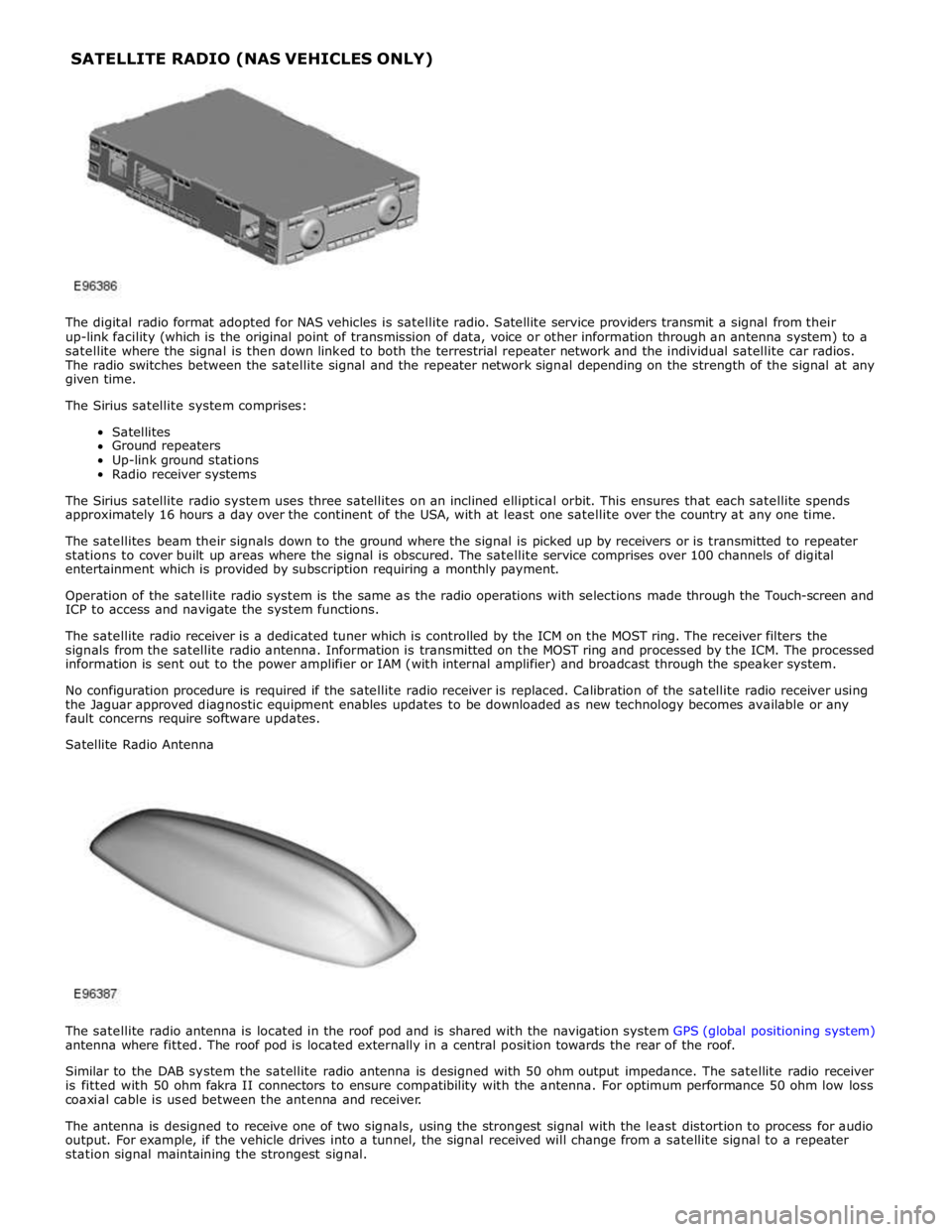
The digital radio format adopted for NAS vehicles is satellite radio. Satellite service providers transmit a signal from their
up-link facility (which is the original point of transmission of data, voice or other information through an antenna system) to a
satellite where the signal is then down linked to both the terrestrial repeater network and the individual satellite car radios.
The radio switches between the satellite signal and the repeater network signal depending on the strength of the signal at any
given time.
The Sirius satellite system comprises:
Satellites
Ground repeaters
Up-link ground stations
Radio receiver systems
The Sirius satellite radio system uses three satellites on an inclined elliptical orbit. This ensures that each satellite spends
approximately 16 hours a day over the continent of the USA, with at least one satellite over the country at any one time.
The satellites beam their signals down to the ground where the signal is picked up by receivers or is transmitted to repeater
stations to cover built up areas where the signal is obscured. The satellite service comprises over 100 channels of digital
entertainment which is provided by subscription requiring a monthly payment.
Operation of the satellite radio system is the same as the radio operations with selections made through the Touch-screen and
ICP to access and navigate the system functions.
The satellite radio receiver is a dedicated tuner which is controlled by the ICM on the MOST ring. The receiver filters the
signals from the satellite radio antenna. Information is transmitted on the MOST ring and processed by the ICM. The processed
information is sent out to the power amplifier or IAM (with internal amplifier) and broadcast through the speaker system.
No configuration procedure is required if the satellite radio receiver is replaced. Calibration of the satellite radio receiver using
the Jaguar approved diagnostic equipment enables updates to be downloaded as new technology becomes available or any
fault concerns require software updates.
Satellite Radio Antenna
The satellite radio antenna is located in the roof pod and is shared with the navigation system GPS (global positioning system)
antenna where fitted. The roof pod is located externally in a central position towards the rear of the roof.
Similar to the DAB system the satellite radio antenna is designed with 50 ohm output impedance. The satellite radio receiver
is fitted with 50 ohm fakra II connectors to ensure compatibility with the antenna. For optimum performance 50 ohm low loss
coaxial cable is used between the antenna and receiver.
The antenna is designed to receive one of two signals, using the strongest signal with the least distortion to process for audio
output. For example, if the vehicle drives into a tunnel, the signal received will change from a satellite signal to a repeater
station signal maintaining the strongest signal. SATELLITE RADIO (NAS VEHICLES ONLY)
Page 1968 of 3039
System Operation
PRINCIPLES OF OPERATION
Pri mary us er cont rol of t he phone s ys tem is vi a t he Touch-s creen and JaguarVoi ce cont rol s wit ch. Selecti on of
'phone/comms ' on the Touch-s creen home menu sends a control si gnal t o t he tel ephone cont rol unit on the MO ST (medi a
ori ent ated sys tems trans port ) ring, opening the phone s ubmenu opt ions .
W hen maki ng an outgoing phone call us ing t he JaguarVoice funct ion t he ICM (informat i on control modul e) proces s es the
anal ogue si gnal from the swi tch i nto a digit al s ignal . The digit al si gnal i s pass ed from the ICM (i nformat ion cont rol
module) onto the MO ST (medi a ori ent ated sys tems trans port ) s yst em t o t he JaguarVoi ce cont rol unit which i s int egral wit h
t he navi gat ion computer.
The navi gat ion comput er s ends an i ns t ructi on via MO ST (medi a ori ent ated sys tems trans port ) t o t he IAM (i ntegrat ed audi o
module) t o t urn on t he mi crophone faci li ty.
The voice command s ignals are rel ayed from t he IAM (i ntegrat ed audio module) vi a the MOST (medi a orientat ed s ys t ems
t ransport) ring t o t he navi gati on comput er for process ing.
The process ed voice command i s rel ayed on the MO ST (medi a ori ent ated sys tems trans port ) ring from the navigat ion
comput er to the phone cont rol module.
Speech out put i nformat ion is t rans ferred from the phone control modul e via t he Bl uet oot h® connect ion to t he cell phone.
Incomi ng cal ls are received from the Bl uet ooth® phone by the phone cont rol module. The i nformat ion is proces sed by the
phone cont rol module and t rans ferred on t he MOST (media ori ent ated s ys tems trans port ) ri ng t o the power ampl ifi er or IAM
(integrat ed audio modul e) for audi o output t hrough the vehicle’s audi o s peaker s ys t e m.
A number of res pons es by t he t el ephone and voice s ys tems are reinforced by mess ages appearing i n the ins trument cl us t er
mes s age center di spl ay. Informat ion is relayed to the mess age cent er from t he phone cont rol module and navigat ion
comput er on t he MOST (media orientat ed s ys t ems t rans port) ring t o t he ICM (informat ion cont rol module).
The ICM (informati on cont rol module) i s the gat eway from t he MOST (media ori ent ated s ys tems trans port ) ri ng t o the
medium s peed CAN. The ICM (informat ion control modul e) trans fers t he mes sage center i nformat ion ont o t he medium
s peed CAN which i s received and process ed for dis play on t he ins t rument clus ter mes s age cente r.
Us ers can pair & dock t heir hands et us ing t hei r phone or t he t ouch s creen. If t here i s no phone already docked wit h t he
s ys t em, a us er can us e t heir phone to search for Bluetoot h Devices. If the vehicl es Bluetooth s ys t em has been s uccess fully
dis covered, t he phone wil l di spl ay "Jaguar" as a device t o pair & connect t o. Us ing t his met hod requires the us er t o enter
t he Jaguar PIN of 1313. Alt ernati vel y, after acces s ing t he phone menu from t he Touch-s creen home menu, sel ect ing
‘Search New’ s earches for the Bluetooth® enabl ed hands et s wit hin range, di spl ays t he ir ident it ies on s creen, and al lows
t he user t o pair and dock the phone ready for use, us ing a random four-di git s ecurit y code di s pl ayed on screen. The s yst em
wil l normall y t ry t o dock (aut omati cal ly) to the las t phone docked, but if a di ffere nt Bluetoot h® enabled phone enters the
car i t wil l become avail abl e on t he s creen’s l is t of hands ets once t he s earch has be en complet ed.
Once a phone is pai red and docked a digit di al s creen i s dis played, incl uding phonebook opti ons . W it h a Bl uet oot h®
compat ibl e hands et and s oft ware vers i on there is the opt ion, through t he s ett ings me nu, t o automat ically downl oad the
cont ents of t he hands et’s phonebook t o the vehicl e s ys t em. Becaus e t here is no indus try s tandard for arranging the
phonebook, t he downloaded li st s from individual hands ets may vary.
Cell phone hands et manufact urers cont inuall y updat e hardware and s oft ware t o s t andard specificati ons laid down by the
Bluet oot h® Special Int eres t Group (SIG), which defi ned how Bluet oot h® woul d work in an aut omoti ve envi ronment.
However, becaus e different makes and models may use different s oft ware, not all hands ets are full y compat ible wit h
Jaguar, but t hrough tes t ing i ndi vi dual handset models Jaguar has produced a lis t of compat ibl e hands et s and the
appropri at e s oft ware vers ion for Jaguar Bl uet ooth® connecti vi ty. Referral to the lis t als o des cri bes how to check the
s oft ware vers i on of each i ndi vidual cell phone manufacturer. This l is t mus t be cons ult ed by us ers , s al es & s ervi ce teams t o
confirm whet her cus tomer's handset s are compat ible or not .
Jaguar is conti nual ly vali dati ng compat ible hands et and software combinati ons . The mos t up-t o-dat e compat ibi lit y l is t wil l
always be avail abl e on-l ine from Jaguar.
• NOTE: To achieve ful l Bl uetooth® hands et functi onal it y it is crucial t hat t he phone s oftware l evel mat ches t he vers ion
detail ed in the lis t of compat ibl e hands et s.
The upgraded hands free profi le of t his s ys tem allows the di spl ay of t he network s ignal st rengt h, net work operat or and
phone bat tery level indicati on on t he vehi cl e dis play. Als o, if appli cable, t he phone hands et wil l s how a "car" or "heads et"
s ymbol t o i ndi cat e i t is i n hands free profil e.
BLUETOOTH®
Bluet oot h® i s a s hort -range RF (radio frequency) t echnology t hat operat es at 2.4 GHz and is capabl e of t rans mit ti ng voice
and data wirel ess l y. The effecti ve range of Bluetoot h® devices is 32 feet (10 meters ) wit h a dat a t ransfer rat e of 1 Mbps .
Bluet oot h® i s es sent iall y a wi rel es s connect ion whi ch operat es wi th the us er's own mobil e hands et , does not have to be
fi xed int o t he car and i s desi gned to funct ion wit hout an external aerial. The hands et can be l ocat ed anywhere wit hin t he
cabi n, even i n a bag, or jacket pocket . It could work from the luggage compart ment , al though t he s ignal could be
compromi sed. The hands et can be charged from t he 12 volt power s ocket or USB (if s upported) whil e in use.
Component Description
Touch-Screen
The Touch-screen communi cat es wit h t he tel ephone control modul e on t he MOST (media orientat ed s ys t ems t rans port) ring
and provides t he pri mary us er int erface and di spl ay of the phone s yst em.
Page 1975 of 3039

7 Microphone 8 Navigation computer 9 VICS (vehicle information and communication system) beacon antenna - Japan only 10 Roof pod antenna module (GPS (global positioning system) antenna) 11 Diversity antenna module (VICS/TMC antenna) 12 ICP (integrated control panel) 13 ICM (information control module) 14 Clock spring 15 Instrument cluster
Authoring Template System Operation
INTRODUCTION TO THE GLOBAL POSITIONING SYSTEM
The system used to calculate the current position of the vehicle is called the GPS. The system utilizes satellites which are owned by the United States Department of Defense. A total of 24 satellites circular orbit the earth every 12 hours at a height
of 20,000 km (12500 miles), and between 5 and 11 of these satellites can be seen from a single point at any given time. The
orbits are tilted to the earth's equator by 55 degrees to ensure coverage of polar regions. Each satellite transmits radio signals
to provide information about the satellite position i.e. latitude, longitude, altitude, almanac data and an accurate time signal
generated by an on-board atomic clock. Each satellite contains four atomic clocks.
The vehicle needs to receive data from at least four different satellites to give a three dimensional fix on its current position.
As the vehicle moves, this information is continually being updated. The computer determines which satellites are 'visible' to
the system and their current position and relationship to each other. Using this information the computer can account for
positional deviations of the satellites and compensate to enhance the accuracy of the navigation system.
www.JagDocs.com
Page 1977 of 3039
In addition to the standard navigation system there are two market dependant systems that supply extra information to the
navigation system and the driver. These are:
TMC (traffic message channel) (Europe only)
VICS (vehicle information and communication system) (Japan only)
The TMC (traffic message channel) is a function of the FM (frequency modulation)RDS (radio data system). The system
broadcasts real-time traffic and weather information. Data messages are received and decoded by the TMC (traffic message
channel) integral receiver and processed by the navigation computer. TMC (traffic message channel) messages can be filtered
by the navigation computer so that only those relevant to the current journey are displayed, allowing the navigation system to
offer dynamic route guidance - alerting the driver of a problem on the planned route and calculating an alternative route to
avoid the incident. All TMC (traffic message channel) events on the map can be viewed not just the ones on the calculated
route.
TMC (traffic message channel) traffic information systems conform to a global standard that has been adopted by traffic data
gatherers, information service providers, broadcasters and vehicle/receiver manufacturers.
All TMC (traffic message channel) receivers use the same list of event codes, while the location database (on the map disc)
contains both a country-specific set of location codes for the strategic European road network.
TMC (traffic message channel) traffic data is currently broadcast in many European countries.
The VICS (vehicle information and communication system) is broadcast in the Japanese market.
The VICS (vehicle information and communication system) supplies information to enable the navigation computer to re-route
the navigation guidance or to inform the vehicle driver of traffic conditions in the vehicles vicinity. Information is provided to
the system through 3 routes:
RF (radio frequency) transmission
Infra-red transmission
FM multiplex transmissions
The RF (radio frequency) transmissions are generally transmitted from road side beacons mainly on expressways. The
information transmitted is as follows:
Traffic congestion
Travel time to next intersection
Traffic conditions in surrounding areas and expressway turn offs
Traffic accidents
Speed limits
Lane regulations
Tire change
Parking availability at expressway service areas and parking areas
Infra-Red transmissions are transmitted from road side beacons on major trunk roads. The information transmitted is:
Traffic congestion and travel time
Traffic accidents
Breakdowns
Road works restrictions
Parking availability
FM transmissions are broadcast as part of the FM multiplex broadcasting system from NHK FM stations. Information transmitted is:
Traffic congestion and travel time for wide areas
Traffic accidents, road works, speed limits and lane restrictions for a wide area
Parking availability information
The traffic data is split from the normal FM transmissions by the diversity antenna module.
Selection of 'Navigation' on the Touch-screen home menu and subsequent sub-menu selection sends a control request signal to
the navigation computer on the MOST (media orientated systems transport) ring. The requested control information is
processed by the navigation computer.
If voice guidance is operational the voice signal information is relayed from the navigation computer on the MOST (media
orientated systems transport) ring to either the IAM (integrated audio unit) or Power Amplifier, dependant on equipment level,
for output on the speaker system. The navigation audio output is through the front speakers whilst the background audio, for
example radio or CD (compact disc), is played at a reduced volume on the rear speakers.
The GPS signal is available to the navigation system at all times when the vehicle ignition is switched on.
Navigation user voice commands are made using the JaguarVoice system. The ICM (information control module) processes the
analogue signal from the JaguarVoice switch into a digital signal. The digital signal is passed from the ICM (information control
module) onto the MOST (media orientated systems transport) system to the JaguarVoice control unit which is integral with the
navigation computer.
The navigation computer sends an instruction via the MOST (media orientated systems transport) ring to the IAM (integrated
audio module) to turn on the microphone facility.
The microphone is hardwired to the IAM (integrated audio module). The spoken voice command signals are relayed from the
IAM (integrated audio module) via the MOST (media orientated systems transport) ring to the navigation computer for
Page 1980 of 3039
the roof pod and is shared with the DAB (digital audio broadcasting) band L antenna or satellite radio antenna where fitted.
The roof pod is located externally in a central position towards the rear of the roof.
The GPS antenna is designed with 50 ohm output impedance. The navigation computer is fitted with 50 ohm fakra II connectors to ensure compatibility with the antenna. For optimum performance 50 ohm low loss coaxial cable is used between
the antenna and navigation computer.
It is possible for the GPS antenna to lose the signal from the GPS satellites; In hilly or tree lined areas
Built up areas with tall buildings
In multi storey car parks
In garages
In tunnels
On bridges
During heavy rain or thunderstorms
When the signal is lost the navigation computer will continue to give guidance using memory mapped data from the DVD map until the signal is restored.
TMC/VICS FM Antenna
Data messages for both TMC (traffic message channel) and VICS (vehicle information and communication system) are received
through the FM antennas and diversity antenna module located in the heated rear window.
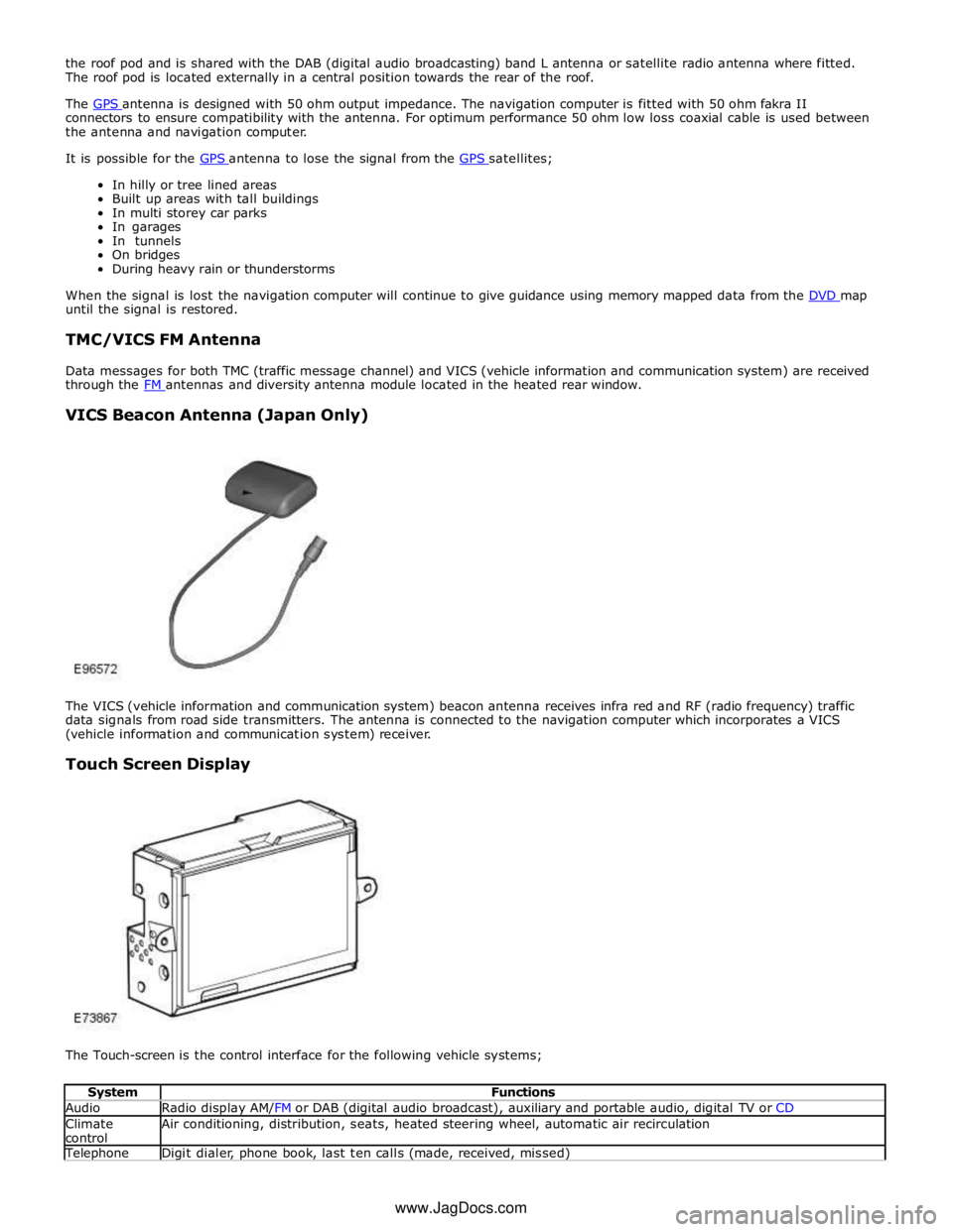
VICS Beacon Antenna (Japan Only)
The VICS (vehicle information and communication system) beacon antenna receives infra red and RF (radio frequency) traffic
data signals from road side transmitters. The antenna is connected to the navigation computer which incorporates a VICS
(vehicle information and communication system) receiver.
Touch Screen Display
The Touch-screen is the control interface for the following vehicle systems;
System Functions Audio Radio display AM/FM or DAB (digital audio broadcast), auxiliary and portable audio, digital TV or CD Climate
control Air conditioning, distribution, seats, heated steering wheel, automatic air recirculation Telephone Digit dialer, phone book, last ten calls (made, received, missed) www.JagDocs.com