2010 JAGUAR XFR radio
[x] Cancel search: radioPage 1987 of 3039
1
2
3
4
5
6
7
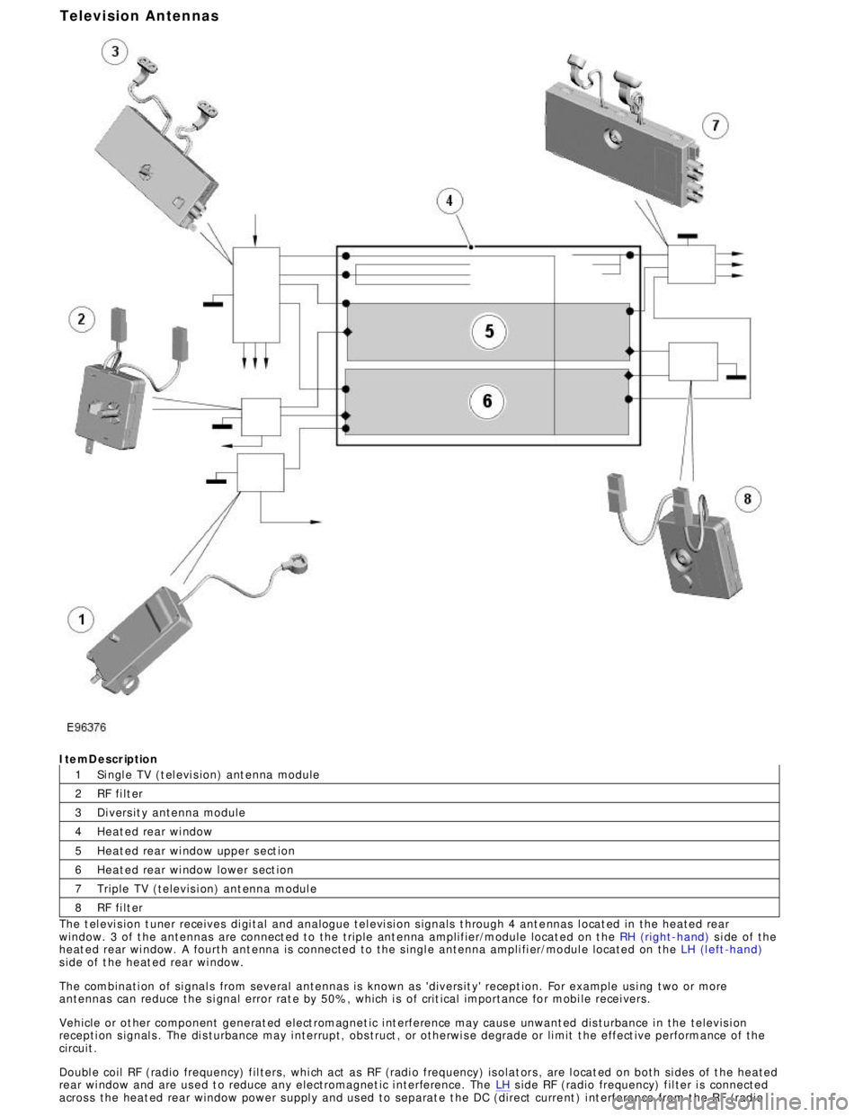
8ItemDescription
Si ngl e TV (t el evi s ion) ant enna module
RF fi lt er
Di vers it y antenna module
Heat ed rear wi ndow
Heat ed rear wi ndow upper s ect ion
Heat ed rear wi ndow lower s ect ion
Triple TV (televis i on) ant enna modul e
RF fi lt er
The t el evi s ion t uner receives di gi tal and analogue tel evi si on s ignals t hrough 4 ant e nnas l ocat ed in the heated rear
window. 3 of t he antennas are connect ed to the triple ant enna amplifier/module locat ed on t he RH (right-hand) s i de of the
heat ed rear wi ndow. A fourth ant enna is connected to the s ingl e antenna ampli fi er/mo dul e located on the LH (l eft -hand)
s ide of t he heat ed rear wi ndow.
The combinati on of si gnal s from several antennas is known as 'divers it y' recept ion. For example us i ng two or more
antennas can reduce the s i gnal error rat e by 50%, which i s of crit ical importance for mobi le recei vers.
Vehicle or ot her component generat ed elect romagnet ic i nt erference may caus e unwant ed dis turbance i n the televis i on
recepti on s ignal s . The di s turbance may i nterrupt, obs truct , or otherwi s e degrade or li mit t he effect ive performance of t he
circuit .
Doubl e coil RF (radio frequency) fil ters, whi ch act as RF (radi o frequency) is olat ors , are l ocat ed on both si des of t he heated
rear wi ndow and are us ed t o reduce any electromagnet ic i nterference. The LH s ide RF (radio frequency) fil ter i s connected
acros s the heat ed rear window power s uppl y and us ed to separat e t he DC (direct curre nt ) i nt erference from t he RF (radioTelevision Antennas
Page 1988 of 3039
1
2
3 frequency) si gnal s. The pos it ive fil ter i s pres ent on al l vehi cl e t ypes and market s .
The ri ght hand s i de doubl e coi l RF (radio frequency) filt er is onl y used in conjunct ion wit h t he tel evi si on antenna modules
and is connect ed acros s the heat ed rear wi ndow ground ci rcuit . If a tel evi si on s ys t e m i s not fi tt ed a fil ter i s used whi ch is
li nked di rectl y t o ground.
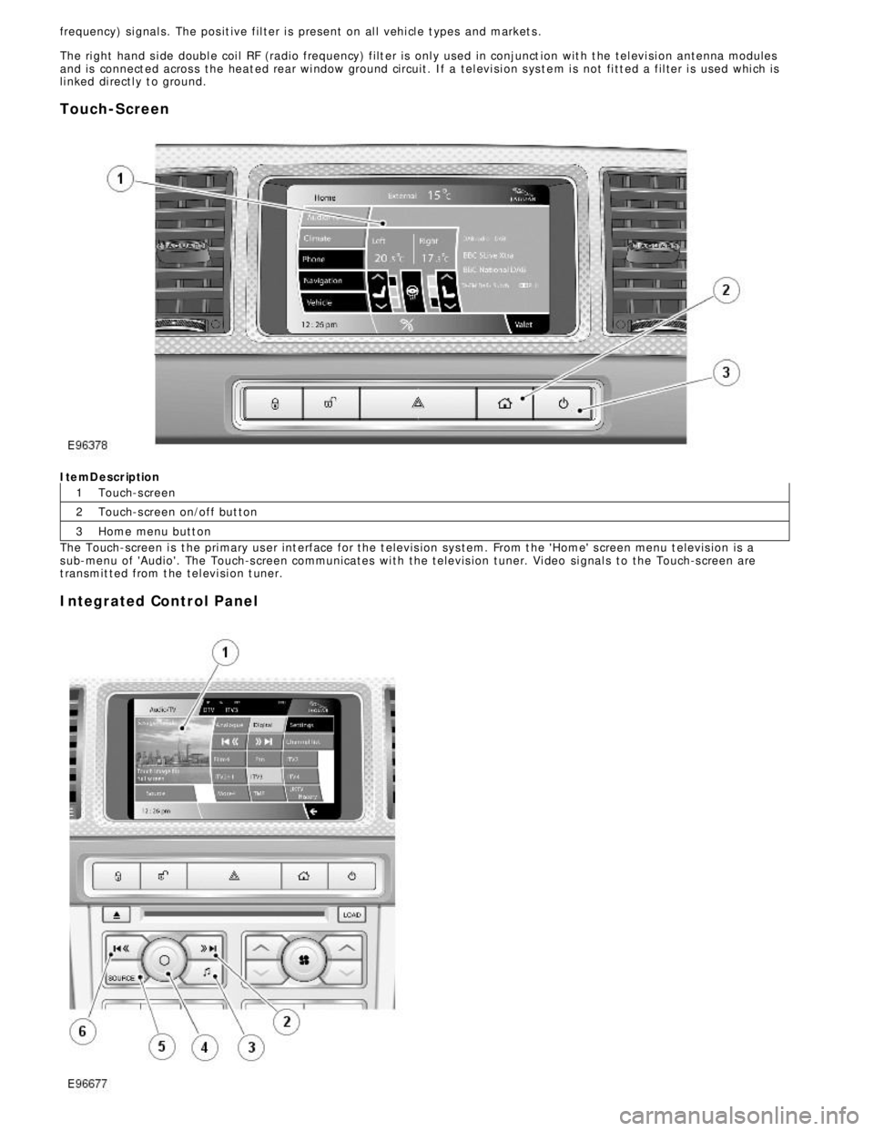
Touch-ScreenItemDescription
Touch-s creen
Touch-s creen on/off but ton
Home menu butt on
The Touch-screen i s t he pri mary us er int erface for the t elevis ion sys tem. From t he 'Home' s creen menu t elevis ion is a
s ub-menu of 'Audio'. The Touch-s creen communicates wi th the t elevis ion tuner. Vi deo si gnal s to the Touch-s creen are
t ransmit ted from t he tel evi si on t uner.
Integrated Control Panel
Page 2007 of 3039
Information and Entertainment System - Satellite Radio Tuner
Removal and Installation
Removal
NOTES:
Removal steps in this procedure may contain installation details.
Some variation in the illustrations may occur, but the essential information is always correct. Published: 09-Dec-2012
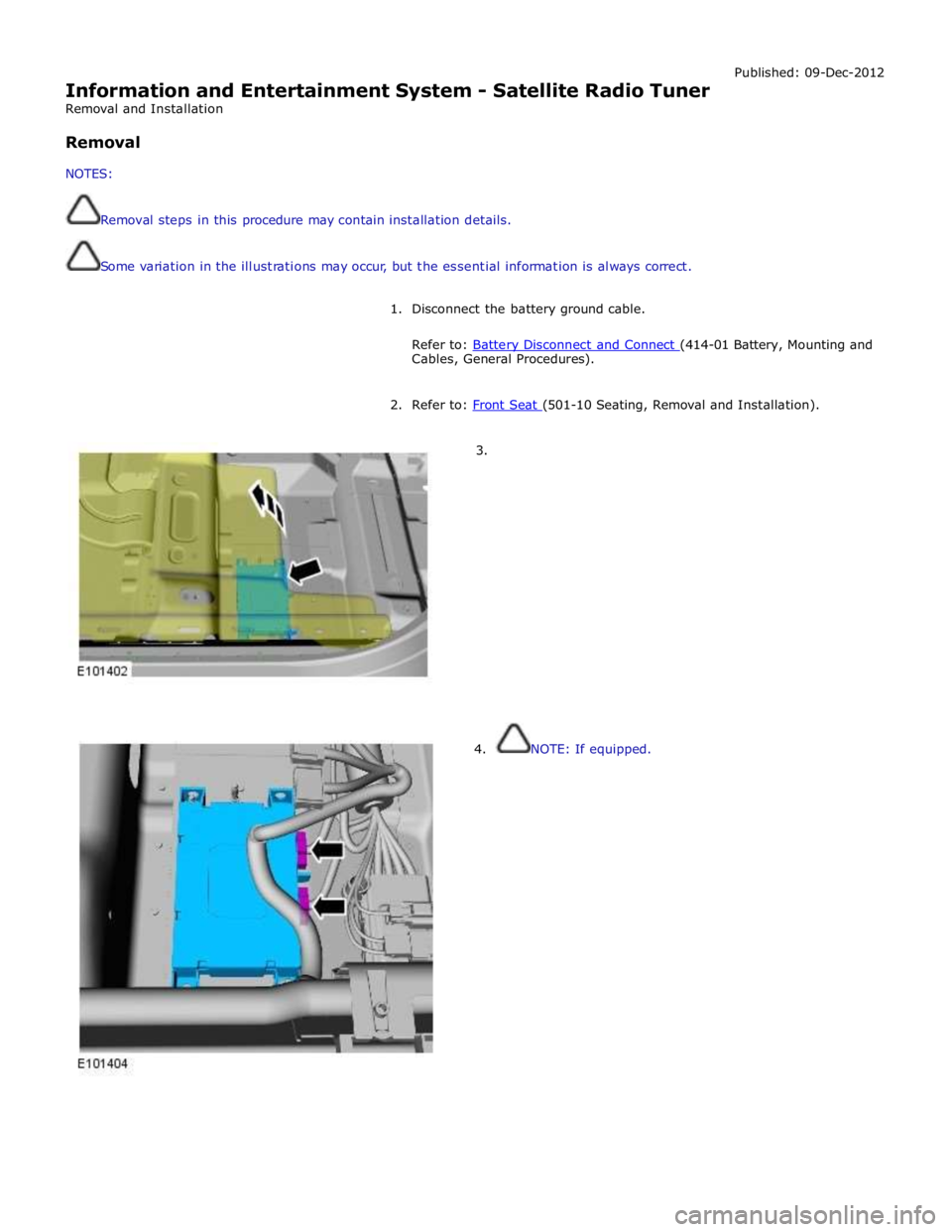
1. Disconnect the battery ground cable.
Refer to: Battery Disconnect and Connect (414-01 Battery, Mounting and Cables, General Procedures).
2. Refer to: Front Seat (501-10 Seating, Removal and Installation).
3.
4. NOTE: If equipped.
Page 2012 of 3039
Symptom Chart - iPOD® Related Faults
Symptom Possible Cause Action iPOD® inoperative
iPOD® configured or
connected incorrectly
If iPOD® playback is faulty but USB playback operates
normally, then follow diagnostic procedures as
specified in pinpoint test A GO to Pinpoint Test A. iPOD® does not operate and
in-car display shows "99" on
the screen
The connected iPOD®
unit has crashed or frozen
See diagnostic procedures as specified in pinpoint test
A1 "Check The Operation Of The iPOD®" below GO to
Pinpoint Test A.
The connected iPOD®
unit's battery is flat and
requires charging
The connected iPOD®
unit's battery is not
holding charge and
requires replacement
See diagnostic procedures as specified in pinpoint test
A2 "Check The iPOD® Battery" below GO to Pinpoint
Test A.
The iPOD® unit is not
compatible with the audio
input control module
See diagnostic procedures as specified in pinpoint test
A4 "Check The iPOD® Is Compatible With The Audio
Input Control Module" below GO to Pinpoint Test A. iPOD® playback drops out and
system reverts to radio input
USB input or iPOD® input
faulty
First check operation of iPOD® playback. If iPOD®
operates normally but USB playback is faulty, then
follow diagnostic procedures as specified in pinpoint
test B GO to Pinpoint Test B. If iPOD® playback is faulty but USB playback operates
normally, then follow diagnostic procedures as
specified in pinpoint test A GO to Pinpoint Test A.
The connected iPOD®
unit has crashed or frozen
See diagnostic procedures as specified in pinpoint test
A1 "Check The Operation Of The iPOD®" below GO to
Pinpoint Test A.
The connected iPOD®
unit's battery is flat and
requires charging
The connected iPOD®
unit's battery is not
holding charge and
requires replacement
See diagnostic procedures as specified in pinpoint test
A2 "Check The iPOD® Battery" below GO to Pinpoint
Test A.
The auxiliary input unit is
faulty
See diagnostic procedures as specified in pinpoint test
A6 "Check The Operation Of The Auxiliary Input Unit"
below GO to Pinpoint Test A. iPOD® unit will not charge
when connected to the audio
input control module
The iPOD® unit is not
compatible with the audio
input control module
See diagnostic procedures as specified in pinpoint test
A4 "Check The iPOD® Is Compatible With The Audio
Input Control Module" below GO to Pinpoint Test A.
The iPOD® dock cable is
not securely installed
The iPOD® dock cable is
faulty
See diagnostic procedures as specified in pinpoint test
A3 "Check The iPOD® Is Charging When Connected To
The Audio Input Control Module" below GO to Pinpoint
Test A. iPOD® unit keeps cutting out
and rebooting
The iPOD® unit is not
compatible with the audio
input control module
See diagnostic procedures as specified in pinpoint test
A4 "Check The iPOD® Is Compatible With The Audio
Input Control Module" below GO to Pinpoint Test A.
The iPOD® dock cable is
not securely installed
The iPOD® dock cable is
faulty
See diagnostic procedures as specified in pinpoint test
A3 "Check The iPOD® Is Charging When Connected To
The Audio Input Control Module" below GO to Pinpoint
Test A.
The connected iPOD®
unit's battery is flat and
requires charging
The connected iPOD®
See diagnostic procedures as specified in pinpoint test
A2 "Check The iPOD® Battery" below GO to Pinpoint
Test A.
Page 2014 of 3039
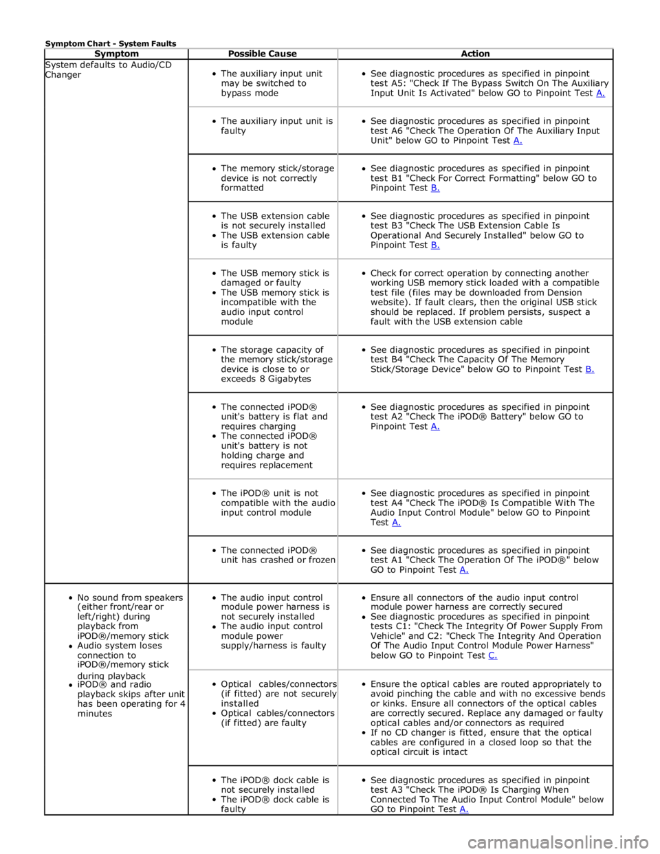
Symptom Chart - System Faults
Symptom Possible Cause Action System defaults to Audio/CD
Changer
The auxiliary input unit
may be switched to
bypass mode
See diagnostic procedures as specified in pinpoint
test A5: "Check If The Bypass Switch On The Auxiliary
Input Unit Is Activated" below GO to Pinpoint Test A.
The auxiliary input unit is
faulty
See diagnostic procedures as specified in pinpoint
test A6 "Check The Operation Of The Auxiliary Input
Unit" below GO to Pinpoint Test A.
The memory stick/storage
device is not correctly
formatted
See diagnostic procedures as specified in pinpoint
test B1 "Check For Correct Formatting" below GO to
Pinpoint Test B.
The USB extension cable
is not securely installed
The USB extension cable
is faulty
See diagnostic procedures as specified in pinpoint
test B3 "Check The USB Extension Cable Is
Operational And Securely Installed" below GO to
Pinpoint Test B.
The USB memory stick is
damaged or faulty
The USB memory stick is
incompatible with the
audio input control
module
Check for correct operation by connecting another
working USB memory stick loaded with a compatible
test file (files may be downloaded from Dension
website). If fault clears, then the original USB stick
should be replaced. If problem persists, suspect a
fault with the USB extension cable
The storage capacity of
the memory stick/storage
device is close to or
exceeds 8 Gigabytes
See diagnostic procedures as specified in pinpoint
test B4 "Check The Capacity Of The Memory
Stick/Storage Device" below GO to Pinpoint Test B.
The connected iPOD®
unit's battery is flat and
requires charging
The connected iPOD®
unit's battery is not
holding charge and
requires replacement
See diagnostic procedures as specified in pinpoint
test A2 "Check The iPOD® Battery" below GO to
Pinpoint Test A.
The iPOD® unit is not
compatible with the audio
input control module
See diagnostic procedures as specified in pinpoint
test A4 "Check The iPOD® Is Compatible With The
Audio Input Control Module" below GO to Pinpoint
Test A.
The connected iPOD®
unit has crashed or frozen
See diagnostic procedures as specified in pinpoint
test A1 "Check The Operation Of The iPOD®" below
GO to Pinpoint Test A.
No sound from speakers
The audio input control
Ensure all connectors of the audio input control (either front/rear or module power harness is module power harness are correctly secured left/right) during not securely installed See diagnostic procedures as specified in pinpoint playback from The audio input control tests C1: "Check The Integrity Of Power Supply From iPOD®/memory stick module power Vehicle" and C2: "Check The Integrity And Operation Audio system loses supply/harness is faulty Of The Audio Input Control Module Power Harness" connection to below GO to Pinpoint Test C. iPOD®/memory stick during playback
Optical cables/connectors
(if fitted) are not securely
installed
Optical cables/connectors
(if fitted) are faulty
Ensure the optical cables are routed appropriately to
avoid pinching the cable and with no excessive bends
or kinks. Ensure all connectors of the optical cables
are correctly secured. Replace any damaged or faulty
optical cables and/or connectors as required
If no CD changer is fitted, ensure that the optical
cables are configured in a closed loop so that the
optical circuit is intact iPOD® and radio playback skips after unit has been operating for 4 minutes
The iPOD® dock cable is
not securely installed
The iPOD® dock cable is
faulty
See diagnostic procedures as specified in pinpoint
test A3 "Check The iPOD® Is Charging When
Connected To The Audio Input Control Module" below
GO to Pinpoint Test A.
Page 2119 of 3039
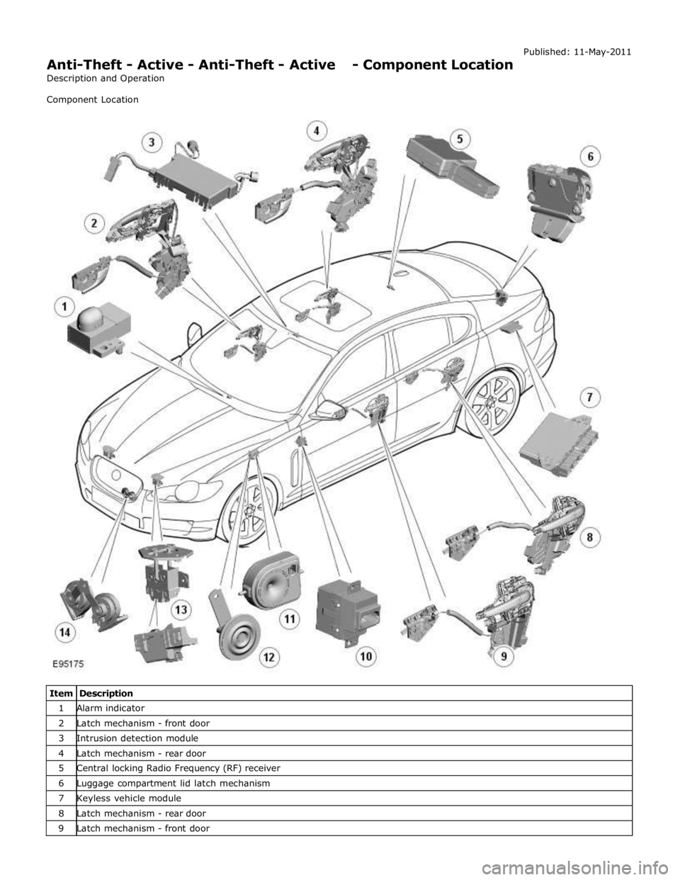
Anti-Theft - Active - Anti-Theft - Active - Component Location
Description and Operation
Component Location Published: 11-May-2011
Item Description 1 Alarm indicator 2 Latch mechanism - front door 3 Intrusion detection module 4 Latch mechanism - rear door 5 Central locking Radio Frequency (RF) receiver 6 Luggage compartment lid latch mechanism 7 Keyless vehicle module 8 Latch mechanism - rear door 9 Latch mechanism - front door
Page 2123 of 3039

7 Central locking - Radio Frequency (RF) receiver 8 Engine compartment lid - latch mechanism 9 Passive sounder 10 Battery backed sounder 11 Alarm indicator 12 Instrument cluster 13 Start control unit 14 Luggage compartment lid - latch mechanism 15 Door latch mechanism - LH (left-hand) rear 16 Door latch mechanism - RH (right-hand) rear 17 Door latch mechanism - RH front 18 Door latch mechanism - LH front 19 Door module - LH rear 20 Door module - RH rear 21 Door module - RH front 22 Door module - LH front 23 Intrusion detection module
Anti-Theft - Active System Operation
The active anti-theft system is available with three different levels of vehicle protection depending on market specification:
Hinged panel sensing
Hinged panel and intrusion sensing
Hinged panel, intrusion and inclination sensing.
The system is controlled by software in the CJB and RJB and indicates a trigger condition: Visually, using the direction indicators, and
Audibly, using the vehicle horn and either a passive or active sounder to indicate a trigger condition.
The passive sounder takes the form of an anti-theft disc horn located at the rear of the engine compartment on the LH side. The active sounder takes the form of a battery backed sounder located in the same position.
Depending on market specification, the battery backed sounder may be fitted with an inclination sensor. Both types of battery
backed sounder are visually identical and can only be identified by their part number. Both are also intelligent units, and
communicate to the CJB over a LIN (local interconnect network) bus connection.
Monitoring of the hinged panels is carried out using switches located in each door latch assembly, the engine-compartment-lid
latch assembly, and the luggage-compartment-lid latch assembly. The condition of the switches is monitored by the CJB.
Monitoring of front door lock status is carried out using switches located in the door latch mechanisms. The condition of the
switches is monitored by the front door modules and transmitted to the CJB over the medium speed CAN (controller area
network) bus.
Monitoring of the cabin interior is carried out using an intrusion detection module mounted behind the roof console. The
intrusion detection module comprises an ultrasonic sound wave sensor to determine if there is movement within the cabin.
Information from the intrusion detection module is communicated to the CJB over a LIN bus connection.
CAUTIONS:
The intrusion detection module electrical connections, particularly those to the sensors mounted in the roof console, are
very delicate and must be handled with care.
The intrusion detection module is an electro-statically sensitive part and should only be handled in an electro-statically
controlled environment.
When armed, the active anti-theft system can be triggered in one of the following ways:
A door ajar switch indicates a door has been opened.
The engine compartment lid or luggage compartment lid ajar switches indicate that either has been opened.
Either front door latch mechanism indicates a door has been unlocked.
The emergency key blade is used to open either the LH front door or luggage compartment.
The CJB or RJB are disconnected (this may result in only a partial trigger).
An attempt is made to start the engine without a valid signal from the Smart Key.
Refer to: Anti-Theft - Passive (419-01B Anti-Theft - Passive, Description and Operation).
Page 2124 of 3039

The battery backed sounder is disconnected (partial trigger only).
The vehicle battery is disconnected on a vehicle fitted with a battery backed sounder (partial trigger only).
The inclination sensor detects a change in vehicle attitude.
The intrusion detection module detects movement within the cabin.
Door Modules Component Description
The door modules provide the interface between the door latch-motors, the door latch-switches and the CJB. The door modules
provide door switch status information and enable the door latch-motors on request from the CJB or the keyless vehicle
module.
Keyless Vehicle Module
The keyless vehicle module interfaces with the Central locking, Radio Frequency (RF) receiver and collects RF signal information
which is transmitted from the Smart Key. This information is translated into commands which are passed on the medium speed
CAN bus to the:
CJB,
RJB,
door modules, and
instrument cluster.
The keyless vehicle module also monitors:
2 interior antennae,
1 luggage compartment antenna,
a rear bumper antenna, and
4 door handle antennae if the passive entry system is fitted.
On vehicles with passive entry, the additional fast latch motors are controlled via the keyless vehicle module and the locking
status is passed to the CJB on the medium speed CAN bus.
Instrument Cluster
The instrument cluster controls the alarm indicator, and in conjunction with the ECM (engine control module), the engine
immobilization. The ECM controls the engine crank and fuel functions and the instrument cluster processes the valid
transponder information.
Alarm Indicator
The alarm indicator is a LED (light emitting diode) located in the body of the sunload/light sensor. When the ignition is off the
indicator gives a visual indication of the active anti-theft system to show if the alarm system is active or not active. Operation
of the alarm indicator is controlled by the instrument cluster which varies the flash rate of the LED to indicate the system
status of the alarm and the immobilization systems.
When the ignition is on, the indicator provides a visual indication of the status of the passive anti-theft (engine
immobilization) system. If the immobilization system is operating correctly, the LED will be illuminated for 3 seconds at
ignition on and then extinguish. If a fault exists in the immobilization system, the LED will be either permanently illuminated
or flashing for 60 seconds. This indicates that a fault exists and fault code has been recorded. After the 60 second period the
LED will flash at different frequencies which indicate the nature of the fault.
Refer to: Anti-Theft - Passive (419-01B Anti-Theft - Passive, Description and Operation).
Passive Anti-Theft Horn
The passive anti-theft horn is hardwired to the CJB which activates the horn when the alarm is triggered.
Battery Backed Sounder
Operation of the battery backed sounder is controlled by the CJB on the LIN bus. The sounder is also connected with a
permanent battery supply via the CJB. An integral, rechargeable battery powers the sounder if the battery power supply from
the CJB is interrupted.
Dependant on vehicle, a incitation sensor is incorporated into the battery backed sounder, to monitor vehicle attitude, see
Inclination Sensor.
Inclination Sensor
The CJB monitors the inclination sensor and will activate the alarm system if the vehicle is being raised.
Intrusion Detection Module
The intrusion detection module comprises an ultrasonic sound wave sensor which monitors the vehicle's interior.
The intrusion detection module is activated with volumetric mode which in turn is enabled when the vehicle is double locked.
The vehicle can be locked and alarmed with the module de-activated if a pet is to be left in the vehicle for example by single-