2010 JAGUAR XFR brake sensor
[x] Cancel search: brake sensorPage 1823 of 3039
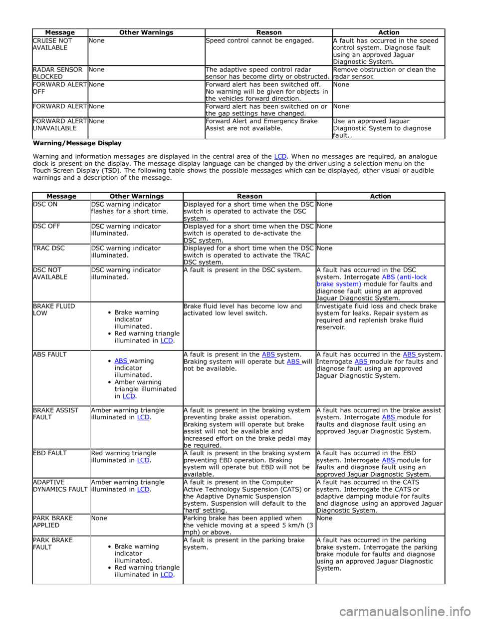
Message Other Warnings Reason Action CRUISE NOT
AVAILABLE None Speed control cannot be engaged.
A fault has occurred in the speed
control system. Diagnose fault
using an approved Jaguar Diagnostic System. RADAR SENSOR
BLOCKED None
The adaptive speed control radar
sensor has become dirty or obstructed. Remove obstruction or clean the
radar sensor. FORWARD ALERT
OFF None
Forward alert has been switched off.
No warning will be given for objects in
the vehicles forward direction. None FORWARD ALERT None
Forward alert has been switched on or
the gap settings have changed. None FORWARD ALERT
UNAVAILABLE None
Forward Alert and Emergency Brake
Assist are not available. Use an approved Jaguar
Diagnostic System to diagnose
fault.. Warning/Message Display
Warning and information messages are displayed in the central area of the LCD. When no messages are required, an analogue clock is present on the display. The message display language can be changed by the driver using a selection menu on the
Touch Screen Display (TSD). The following table shows the possible messages which can be displayed, other visual or audible
warnings and a description of the message.
Message Other Warnings Reason Action DSC ON
DSC warning indicator
flashes for a short time. Displayed for a short time when the DSC
switch is operated to activate the DSC system. None DSC OFF
DSC warning indicator
illuminated. Displayed for a short time when the DSC
switch is operated to de-activate the
DSC system. None TRAC DSC
DSC warning indicator
illuminated. Displayed for a short time when the DSC
switch is operated to activate the TRAC
DSC system. None DSC NOT
AVAILABLE DSC warning indicator
illuminated. A fault is present in the DSC system.
A fault has occurred in the DSC
system. Interrogate ABS (anti-lock
brake system) module for faults and
diagnose fault using an approved Jaguar Diagnostic System. BRAKE FLUID
LOW
Brake warning
indicator
illuminated.
Red warning triangle
illuminated in LCD. Brake fluid level has become low and
activated low level switch. Investigate fluid loss and check brake
system for leaks. Repair system as
required and replenish brake fluid
reservoir. ABS FAULT
ABS warning indicator
illuminated.
Amber warning
triangle illuminated
in LCD. A fault is present in the ABS system. Braking system will operate but ABS will not be available. A fault has occurred in the ABS system. Interrogate ABS module for faults and diagnose fault using an approved
Jaguar Diagnostic System. BRAKE ASSIST
FAULT Amber warning triangle
illuminated in LCD. A fault is present in the braking system
preventing brake assist operation.
Braking system will operate but brake
assist will not be available and
increased effort on the brake pedal may
be required. A fault has occurred in the brake assist
system. Interrogate ABS module for faults and diagnose fault using an
approved Jaguar Diagnostic System. EBD FAULT
Red warning triangle
illuminated in LCD. A fault is present in the braking system
preventing EBD operation. Braking
system will operate but EBD will not be
available. A fault has occurred in the EBD
system. Interrogate ABS module for faults and diagnose fault using an approved Jaguar Diagnostic System. ADAPTIVE
DYNAMICS FAULT Amber warning triangle
illuminated in LCD. A fault is present in the Computer
Active Technology Suspension (CATS) or
the Adaptive Dynamic Suspension
system. Suspension will default to the
'hard' setting. A fault has occurred in the CATS
system. Interrogate the CATS or
adaptive damping module for faults
and diagnose using an approved Jaguar Diagnostic System. PARK BRAKE
APPLIED None
Parking brake has been applied when
the vehicle moving at a speed 5 km/h (3 mph) or above. None PARK BRAKE
FAULT
Brake warning
indicator
illuminated.
Red warning triangle
illuminated in LCD. A fault is present in the parking brake
system. A fault has occurred in the parking
brake system. Interrogate the parking
brake module for faults and diagnose
using an approved Jaguar Diagnostic
System.
Page 1824 of 3039
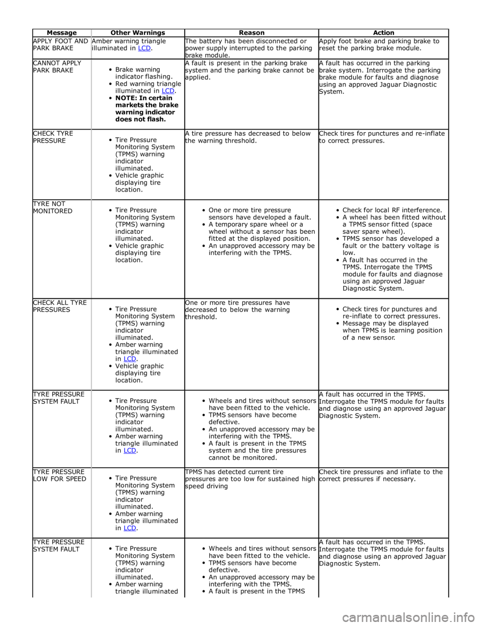
Message Other Warnings Reason Action APPLY FOOT AND
PARK BRAKE Amber warning triangle
illuminated in LCD. The battery has been disconnected or
power supply interrupted to the parking
brake module. Apply foot brake and parking brake to
reset the parking brake module. CANNOT APPLY
PARK BRAKE
Brake warning
indicator flashing.
Red warning triangle
illuminated in LCD. NOTE: In certain
markets the brake
warning indicator
does not flash. A fault is present in the parking brake
system and the parking brake cannot be
applied. A fault has occurred in the parking
brake system. Interrogate the parking
brake module for faults and diagnose
using an approved Jaguar Diagnostic
System. CHECK TYRE
PRESSURE
Tire Pressure
Monitoring System
(TPMS) warning
indicator
illuminated.
Vehicle graphic
displaying tire
location. A tire pressure has decreased to below
the warning threshold. Check tires for punctures and re-inflate
to correct pressures. TYRE NOT
MONITORED
Tire Pressure
Monitoring System
(TPMS) warning
indicator
illuminated.
Vehicle graphic
displaying tire
location.
One or more tire pressure
sensors have developed a fault.
A temporary spare wheel or a
wheel without a sensor has been
fitted at the displayed position.
An unapproved accessory may be
interfering with the TPMS.
Check for local RF interference.
A wheel has been fitted without
a TPMS sensor fitted (space
saver spare wheel).
TPMS sensor has developed a
fault or the battery voltage is
low.
A fault has occurred in the
TPMS. Interrogate the TPMS
module for faults and diagnose
using an approved Jaguar
Diagnostic System. CHECK ALL TYRE
PRESSURES
Tire Pressure
Monitoring System
(TPMS) warning
indicator
illuminated.
Amber warning
triangle illuminated
in LCD. Vehicle graphic
displaying tire
location. One or more tire pressures have
decreased to below the warning
threshold.
Check tires for punctures and
re-inflate to correct pressures.
Message may be displayed
when TPMS is learning position
of a new sensor. TYRE PRESSURE
SYSTEM FAULT
Tire Pressure
Monitoring System
(TPMS) warning
indicator
illuminated.
Amber warning
triangle illuminated
in LCD.
Wheels and tires without sensors
have been fitted to the vehicle.
TPMS sensors have become
defective.
An unapproved accessory may be
interfering with the TPMS.
A fault is present in the TPMS
system and the tire pressures
cannot be monitored. A fault has occurred in the TPMS.
Interrogate the TPMS module for faults
and diagnose using an approved Jaguar
Diagnostic System. TYRE PRESSURE
LOW FOR SPEED
Tire Pressure
Monitoring System
(TPMS) warning
indicator
illuminated.
Amber warning
triangle illuminated
in LCD. TPMS has detected current tire
pressures are too low for sustained high
speed driving Check tire pressures and inflate to the
correct pressures if necessary. TYRE PRESSURE
SYSTEM FAULT
Tire Pressure
Monitoring System
(TPMS) warning
indicator
illuminated.
Amber warning
triangle illuminated
Wheels and tires without sensors
have been fitted to the vehicle.
TPMS sensors have become
defective.
An unapproved accessory may be
interfering with the TPMS.
A fault is present in the TPMS A fault has occurred in the TPMS.
Interrogate the TPMS module for faults
and diagnose using an approved Jaguar
Diagnostic System.
Page 1826 of 3039
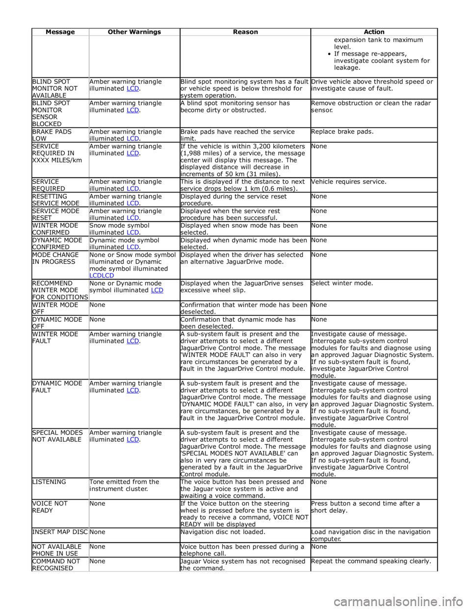
Message Other Warnings Reason Action expansion tank to maximum
level.
If message re-appears,
investigate coolant system for
leakage. BLIND SPOT
MONITOR NOT
AVAILABLE Amber warning triangle
illuminated LCD. Blind spot monitoring system has a fault
or vehicle speed is below threshold for system operation. Drive vehicle above threshold speed or
investigate cause of fault. BLIND SPOT
MONITOR
SENSOR
BLOCKED Amber warning triangle
illuminated LCD. A blind spot monitoring sensor has
become dirty or obstructed. Remove obstruction or clean the radar
sensor. BRAKE PADS
LOW Amber warning triangle
illuminated LCD. Brake pads have reached the service
limit. Replace brake pads. SERVICE
REQUIRED IN
XXXX MILES/km Amber warning triangle
illuminated LCD. If the vehicle is within 3,200 kilometers
(1,988 miles) of a service, the message
center will display this message. The
displayed distance will decrease in
increments of 50 km (31 miles). None SERVICE
REQUIRED Amber warning triangle
illuminated LCD. This is displayed if the distance to next
service drops below 1 km (0.6 miles). Vehicle requires service. RESETTING
SERVICE MODE Amber warning triangle
illuminated LCD. Displayed during the service reset procedure. None SERVICE MODE
RESET Amber warning triangle
illuminated LCD. Displayed when the service rest procedure has been successful. None WINTER MODE
CONFIRMED Snow mode symbol
illuminated LCD. Displayed when snow mode has been
selected. None DYNAMIC MODE
CONFIRMED Dynamic mode symbol
illuminated LCD. Displayed when dynamic mode has been
selected. None MODE CHANGE
IN PROGRESS None or Snow mode symbol
illuminated or Dynamic
mode symbol illuminated
LCDLCD Displayed when the driver has selected
an alternative JaguarDrive mode. None RECOMMEND
WINTER MODE
FOR CONDITIONS None or Dynamic mode
symbol illuminated LCD Displayed when the JaguarDrive senses
excessive wheel slip. Select winter mode. WINTER MODE
OFF None
Confirmation that winter mode has been
deselected. None DYNAMIC MODE
OFF None
Confirmation that dynamic mode has
been deselected. None WINTER MODE
FAULT Amber warning triangle
illuminated LCD. A sub-system fault is present and the
driver attempts to select a different
JaguarDrive Control mode. The message
'WINTER MODE FAULT' can also in very
rare circumstances be generated by a
fault in the JaguarDrive Control module. Investigate cause of message.
Interrogate sub-system control
modules for faults and diagnose using
an approved Jaguar Diagnostic System.
If no sub-system fault is found,
investigate JaguarDrive Control
module. DYNAMIC MODE
FAULT Amber warning triangle
illuminated LCD. A sub-system fault is present and the
driver attempts to select a different
JaguarDrive Control mode. The message
'DYNAMIC MODE FAULT' can also, in very
rare circumstances, be generated by a
fault in the JaguarDrive Control module. Investigate cause of message.
Interrogate sub-system control
modules for faults and diagnose using
an approved Jaguar Diagnostic System.
If no sub-system fault is found,
investigate JaguarDrive Control
module. SPECIAL MODES
NOT AVAILABLE Amber warning triangle
illuminated LCD. A sub-system fault is present and the
driver attempts to select a different
JaguarDrive Control mode. The message
'SPECIAL MODES NOT AVAILABLE' can
also in very rare circumstances be
generated by a fault in the JaguarDrive
Control module. Investigate cause of message.
Interrogate sub-system control
modules for faults and diagnose using
an approved Jaguar Diagnostic System.
If no sub-system fault is found,
investigate JaguarDrive Control
module. LISTENING Tone emitted from the
instrument cluster. The voice button has been pressed and
the Jaguar voice system is active and awaiting a voice command. None VOICE NOT
READY None
If the Voice button on the steering
wheel is pressed before the system is
ready to receive a command, VOICE NOT
READY will be displayed Press button a second time after a
short delay. INSERT MAP DISC None Navigation disc not loaded.
Load navigation disc in the navigation
computer. NOT AVAILABLE
PHONE IN USE None
Voice button has been pressed during a telephone call. None COMMAND NOT
RECOGNISED None
Jaguar Voice system has not recognised
the command. Repeat the command speaking clearly.
Page 1828 of 3039
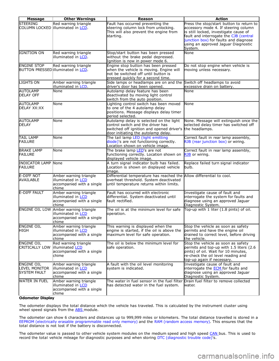
STEERING
COLUMN LOCKED Red warning triangle
illuminated in LCD. Fault has occurred preventing the
steering column lock from unlocking. This will also prevent the engine from
starting. Press the stop/start button to return to
accessory mode 4. If steering column
is still locked, investigate cause of
fault and interrogate the CJB (central junction box) for faults and diagnose
using an approved Jaguar Diagnostic System. IGNITION ON
Red warning triangle
illuminated in LCD. Stop/start button has been pressed
without the brake pedal depressed. Ignition is now in power mode 6. None ENGINE STOP
BUTTON PRESSED Red warning triangle
illuminated in LCD. Engine stop button has been pressed
when the vehicle is moving. Engine will
not be switched off until button is pressed quickly for a second time. Do not stop engine when vehicle is
moving unless necessary. LIGHTS ON
Amber warning triangle
illuminated in LCD. Side lamps or headlamps are on and the
driver's door has been opened. Switch off headlamps to avoid
excessive drain on battery. AUTOLAMP
DELAY OFF None
Autolamp delay feature has been
deactivated by moving light control
switch from the auto position. None AUTOLAMP
DELAY XX:XX None
Lighting control switch has been moved
to one of the 4 autolamp delay
positions. Message displays delay timer period selected. None AUTOLAMP
DELAY None
Autolamp delay is selected on the light
control switch and the driver has
switched off ignition and opened driver's
door initiating the autolamp delay. None. Message will extinguish once the
selected delay timer has switched off
the headlamps. TAIL LAMP
FAILURE None The tail lamp LED (light emitting
diode)'s are not functioning correctly.
Location shown on vehicle image. Correct fault in rear lamp assembly,
RJB (rear junction box) or wiring. BRAKE LAMP
FAILURE None The brake lamp LED's are not functioning correctly. Location shown on displayed vehicle image. Correct fault in rear lamp assembly,
RJB or wiring. INDICATOR LAMP
FAILURE None
A turn signal indicator bulb has failed.
Location is shown on displayed vehicle image. Replace failed turn signal indicator
bulb. E-DIFF NOT
AVAILABLE Amber warning triangle
illuminated in LCD accompanied with a single
chime Differential temperature has reached the
overheat threshold. System deactivated
until temperature returns within limits. Allow differential to cool. E-DIFF FAULT
Amber warning triangle
illuminated in LCD accompanied with a single
chime Fault has occurred with electronic
differential. System deactivated until
fault rectified. Investigate cause of fault and
interrogate the system for faults and
diagnose using an approved Jaguar Diagnostic System. ENGINE OIL LOW
Amber warning triangle
illuminated in LCD accompanied with a single
chime The oil is at the minimum level for safe
operation. Top-up with 1 liter (1.8 pints) of oil. ENGINE OIL
HIGH Amber warning triangle
illuminated in LCD accompanied with a single
chime This warning is displayed when the
engine is started, if the oil is above the
maximum level for safe operation. Stop the vehicle as soon as safety
permits and have the engine oil
drained to correct level, before driving
the vehicle. ENGINE OIL
CRITICALLY LOW Red warning triangle
illuminated LCD accompanied with a single
chime The oil is below the minimum level for
safe operation. Stop the vehicle as soon as safety
permits and top-up with 1.5 liters (2.6
pints) of oil. Wait for 10 minutes,
re-check the oil level reading and top-up again if necessary. ENGINE OIL
LEVEL MONITOR
SYSTEM FAULT Amber warning triangle
illuminated in LCD accompanied with a single
chime A fault with the oil level monitoring
system is indicated. Investigate cause of fault and
interrogate the ECM for faults and diagnose using an approved Jaguar Diagnostic System. WATER IN FUEL
Amber warning triangle
illuminated in LCD accompanied with a single
chime The water in fuel sensor in the fuel filter
has detected water in the fuel system. Drain fuel filter to remove collected
water. Odometer Display
The odometer displays the total distance which the vehicle has traveled. This is calculated by the instrument cluster using
wheel speed signals from the ABS module.
The odometer can show 6 characters and distances up to 999,999 miles or kilometers. The total distance travelled is stored in a
EEPROM (electrically erasable programmable read only memory) and the RAM (random access memory). This ensures that the
total distance is not lost if the battery is disconnected.
The odometer value is passed to other vehicle system modules on the medium speed and high speed CAN bus. This is used to record the total vehicle mileage for diagnostic purposes and when storing DTC (diagnostic trouble code)'s.
Page 1848 of 3039
information from other systems:
ABS (anti-lock brake system) module - Road speed signal
TCM (transmission control module) - Reverse gear engaged signal
Trailer module - Trailer attached to vehicle
The module also outputs messages on the medium speed CAN bus which are received by the integrated audio module. The integrated audio module processes these messages and converts them into Media Orientated System Transport (MOST) signals
which are passed to the audio system power amplifier. These signals are then used by the power amplifier to emit the
applicable warning tones from the front or rear audio speakers when an object is detected by the front or rear parking aid
sensors. A warning tone can also be emitted to alert the driver to a fault in the parking aid system.
The control module has a diagnostic connection via the medium speed CAN bus to enable faults to be retrieved using the
Jaguar approved diagnostic equipment. Additionally an on-board diagnostic routine within the control module constantly
monitors the system and alerts the driver to a system fault by emitting a 3 second continuous tone through the rear audio
system speakers when the ignition is switched on. If front parking aid sensors are fitted, the control switch LED will also flash
6 times.
Parking Aid Sensors
Four ultrasonic sensors are located in the front (if fitted) and rear bumpers.
Each sensor has a three pin connector which mates with a bumper harness, which in turn is connected to the main body
harness. Three pins provide for power supply, ground and signal lines to and from the parking aid module.
The parking aid module controls the operation of each sensor using a digital output on the signal line. The module controls the
sensor in one of two modes; combined transmitter and receiver mode or receiver mode only.
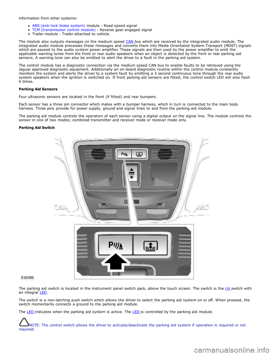
Parking Aid Switch
The parking aid switch is located in the instrument panel switch pack, above the touch screen. The switch is the LH switch with an integral LED.
The switch is a non-latching push switch which allows the driver to select the parking aid system on or off. When pressed, the
switch momentarily connects a ground to the parking aid module.
The LED indicates when the parking aid system is active. The LED is controlled by the parking aid module.
NOTE: The control switch allows the driver to activate/deactivate the parking aid system if operation is required or not
required.
Page 2033 of 3039
Halogen Low/high Beam Headlamp
The halogen low/high beam headlamp uses a projector lens, similar to the xenon headlamp. The projector module comprises
an ellipsoidal lens and a reflector. The projector reflector collects the light produced by the halogen bulb and projects the light
into a focal plane containing a shield. The contour of the shield is projected onto the road by the lens. The low/high beam
bulbs are quartz halogen and are retained in the headlamp unit with conventional wire retaining clips.
A tourist lever mechanism is located on the right hand side of the projector module. This mechanism moves a flap to blank off
a portion of the beam spread to enable the vehicle to be driven in opposite drive hand markets without applying blanking
decals to the headlamp lens. The beam is changed by removing the access cover at the rear of the lamp assembly and moving
a small lever located near the bulb holder, at the side of the projector.
Halogen High Beam Headlamp - Xenon and Halogen
The xenon and halogen headlamps use a complex surface reflector for the halogen fill in high beam lamp only lighting unit,
which is of the same design on both headlamp types. This type of reflector has the reflector divided into separate parabolic
segments, with each segment having a different focal length.
The high beam headlamp bulbs are quartz halogen and are retained in the headlamp unit with conventional wire retaining
clips.
Cornering Lamps
NOTE: The cornering lamps are not fitted to NAS vehicles.
The cornering lamps are an optional feature designed to illuminate the direction of travel when cornering at low speeds. The
design of the lens projects a spread of light from the vehicle at approximately 45 degrees to the vehicle axis. The cornering
lamp is incorporated into the headlamp assembly and shares the same housing as the low beam headlamp. The cornering lamp
uses a 35W Halogen H8 bulb which is permanently located in an integral holder which is connected on the headlamp housing.
The holder is located in an aperture in the headlamp housing and rotated to lock. The bulb is accessible via a removable cover
on the base of the headlamp housing.
The cornering lamps are controlled by the LH steering column multifunction switch with the lighting control switch in the headlamp position and the ignition in power mode 6. The cornering lamps are supplied power via the ignition circuit to ensure
that they do not function with the headlamp delay feature. The cornering lamps are deactivated if the vehicle speed exceeds
25 mph (40 km/h). Only one cornering lamp will illuminate at any one time. If the left hand turn signal indicators are selected
on, the left hand cornering lamp will be illuminated and vice versa, providing the vehicle speed and lighting control switch
positions are correct.
Static Bending Lamps
NOTE: The static bending lamps are not fitted to NAS vehicles.
The static bending lamps are designed to illuminate the direction of travel when cornering at low speeds. The static bending
lamp functionality, which is controlled by the CJB and the headlamp leveling module, operates using inputs from the steering angle sensor and vehicle speed information from the ABS (anti-lock brake system) module. The static bending lamp is
incorporated into the headlamp assembly and shares the same housing as the low beam headlamp. The design of the lens
projects a spread of light from the vehicle at approximately 45 degrees to the vehicle axis. The static bending lamp uses a
35W Halogen H8 bulb which locates in a holder which is connected via wires to the main connector on the headlamp housing.
The holder is located in an aperture in the headlamp housing and rotated to lock. The bulb is accessible via a removable cover
at the rear of the headlamp housing.
The static bending lamps operate with a steering angle sensor CAN bus signal which is received by the CJB. The CJB monitors this signal and vehicle speed and activates the static bending lamp bulb. When the operation parameters of the lamp are
reached, the CJB fades the static bending lamp bulb on using a PWM (pulse width modulation) voltage over a period of approximately 2 seconds. When the lamp is switched off, the CJB fades the bulb off by decreasing the PWM voltage in a linear manner depending on steering angle and vehicle speed. The cornering lamps can only be active for a maximum of 3 minutes.
NOTE: Static bending lamps only operate when the transmission is in DRIVE or in SPORT.
Turn Signal Indicators
The turn signal indicator lamp is incorporated into the outer part of the headlamp assembly. The turn signal indicator lamp
uses a PY21W bayonet orange colored bulb in ROW markets, a S8W 27/7W wedge bulb is used in NAS markets. The bulb is
fitted into a holder which connects with contacts in the headlamp housing. The holder is fitted into an aperture in the
headlamp housing and rotated to lock into position.
When active, the turn signal indicator lamps will flash at a frequency cycle of 380ms on and 380ms off. If a bulb fails, the
remaining turn signal lamps bulbs continue to flash at normal speed. The turn signal indicators in the instrument cluster will
flash at double speed to indicate the bulb failure to the driver.
Side Lamps
The side lamp is located between the headlamp projector module and the high bean headlamp. The side lamp uses a W5W
wedge fitting bulb which locates in a holder which connected via wires to the main connector on the headlamp housing. The
holder is a push fit into a receptacle in the headlamp housing. The bulb is accessible by removal of the inner cover on the rear
of the headlamp housing. Access to the bulb requires removal of the headlamp from the vehicle. The side lamps are operated
by selecting side lamps or headlamps on the lighting control switch. The side lamps are functional at all times and are
Page 2066 of 3039
Published: 11-May-2011
Daytime Running Lamps (DRL) - Daytime Running Lamps (DRL) - System
Operation and Component Description
Description and Operation
CENTRAL JUNCTION BOX (CJB) System Operation
The CJB (central junction box) controls the operation of the DRL (daytime running lamps). The DRL are activated once the CJB detects an ignition on power mode 6 signal.
The CJB also monitors the lighting control switch and the auto lamps feature and overrides the DRL if required.
DAYTIME RUNNING LAMPS - CANADA Component Description
The DRL for this market use full intensity low beam headlamps. The side marker lamps, tail lamps and license plate lamps will be on, but instrument cluster illumination will be off. DRL are active when the following parameters are met:
PARK is not selected on the electronic transmission selector
Electronic Parking Brake (EPB) is off
Power mode 6 (ignition on) detected by the CJB The CJB receives an engine running signal The lighting control switch is in the off or side lamps position.
NOTES:
If the lighting control switch is moved to the headlamp position, DRL are deactivated and normal side lamp and headlamp functionality is operational.
When DRL are active, the headlamp flash function using the left hand steering column multifunction switch will operate normally.
The high beam headlamp function using the left hand steering column stalk switch will be deactivated. When the transmission
is in PARK, DRL are turned off. This is to reduce battery discharge during long periods of engine idling in cold climate conditions. When the electronic transmission selector is moved from the PARK position, normal DRL functionality is restored.
DAYTIME RUNNING LAMPS - DENMARK, HOLLAND, NORWAY, SWEDEN, FINLAND AND POLAND
NOTE: DRL for Poland is on vehicles from 2008MY.
DRL for these markets use full intensity low beam headlamps. Side lamps and license plate lamps will be on, but instrument cluster illumination will be off. DRL are active when the following parameters are met:
Power mode 6 (ignition on) detected by the CJB The CJB receives an engine running signal The lighting control switch is in the off position.
NOTE: When DRL are active, the headlamp flash function using the left hand steering column multifunction switch will operate normally. The high beam headlamp function using the left hand steering column stalk switch will be deactivated.
If the lighting control switch is moved to the side lamp or headlamp positions, DRL are deactivated and normal side lamp and headlamp functionality is operational.
AUTOMATIC HEADLAMPS
On vehicles fitted with the automatic headlamps feature, DRL are overridden if the lighting control switch is in the 'Auto' position and the CJB receives a signal from the rain/light sensor to activate the exterior lights.
When the CJB receives a signal to de-activate the automatic headlamps feature the DRL function is restored providing the parameters for DRL activation are met.
Page 2091 of 3039

DTC Description Possible Cause Action B1D2711
Heater Coolant
Pump
Heater coolant pump control
circuit - short to ground Carry out any pinpoint tests associated with this DTC
using the manufacturer approved diagnostic system.
Refer to the electrical circuit diagrams and check heater
coolant pump control circuit for short to ground B1D2713
Heater Coolant
Pump
Heater coolant pump control
circuit - open circuit Carry out any pinpoint tests associated with this DTC
using the manufacturer approved diagnostic system.
Refer to the electrical circuit diagrams and check heater
coolant pump control circuit for open circuit B1D9796 Tilt Sensor
Component internal failure Suspect the battery backed sounder, check and install a
new battery backed sounder as required P057112
Brake Switch A
Circuit
Footbrake switch circuit - short
to power Refer to the electrical circuit diagrams and check
footbrake switch circuit for short to power P080111
Reverse Inhibit
Control Circuit
Electrochromic rear view mirror,
reverse inhibit circuit - short to
ground Carry out any pinpoint tests associated with this DTC
using the manufacturer approved diagnostic system.
Refer to the electrical circuit diagrams and check
electrochromic rear view mirror, reverse inhibit circuit for
short to ground P080112
Reverse Inhibit
Control Circuit
Electrochromic rear view mirror,
reverse inhibit circuit - short to
power Refer to the electrical circuit diagrams and check
electrochromic rear view mirror, reverse inhibit circuit for
short to power P080113
Reverse Inhibit
Control Circuit
Electrochromic rear view mirror,
reverse inhibit circuit - open
circuit Refer to the electrical circuit diagrams and check
electrochromic rear view mirror, reverse inhibit circuit for
open circuit P085013
Park/Neutral Switch
Input Circuit
Park/Neutral signal circuit -
open circuit Refer to the electrical circuit diagrams and check
Park/Neutral signal circuit for open circuit P162413 Anti-theft System
RJB anti-theft signal circuit -
open circuit Refer to the electrical circuit diagrams and check RJB
anti-theft signal circuit for open circuit P254F13
Engine Hood Switch
Circuit/Open
Hood ajar switch signal circuit -
open circuit Refer to the electrical circuit diagrams and check hood
ajar switch signal circuit for open circuit U001988
Low Speed CAN
Communication Bus
Bus OFF Carry out any pinpoint tests associated with this DTC
using the manufacturer approved diagnostic system. U014200
Lost
Communication
With Body Control
Module "B"
No sub type information Carry out any pinpoint tests associated with this DTC
using the manufacturer approved diagnostic system. U015500
Lost
Communication
With Instrument
Panel Cluster (IPC)
Control Module
No sub type information Carry out any pinpoint tests associated with this DTC
using the manufacturer approved diagnostic system. U015600
Lost
Communication
With Information
Center "A"
No sub type information Carry out any pinpoint tests associated with this DTC
using the manufacturer approved diagnostic system. U016400
Lost
Communication
With HVAC Control
Module
No sub type information Carry out any pinpoint tests associated with this DTC
using the manufacturer approved diagnostic system. U016800
Lost
Communication
With Vehicle
Security Control
Module
No sub type information Check power and ground supplies to vehicle security
module U019900
Lost
Communication
With "Door Control
Module A"
No sub type information Carry out any pinpoint tests associated with this DTC
using the manufacturer approved diagnostic system. U020000
Lost
Communication
With "Door Control
Module B"
No sub type information Carry out any pinpoint tests associated with this DTC
using the manufacturer approved diagnostic system.