2010 JAGUAR XFR Timing
[x] Cancel search: TimingPage 1794 of 3039

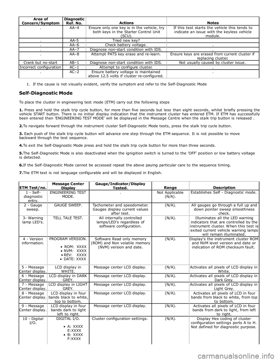
Area of
Concern/Symptom Diagnostic
Ref. No.
Actions
Notes . AA–4
Ensure only one key is in the vehicle, try
both keys in the Starter Control Unit (SCU). If this test starts the vehicle this tends to
indicate an issue with the keyless vehicle
module. . AA-5 Tried new key? . AA–6 Check battery voltage. . . AA–7 Diagnose non-start condition with IDS. . . AA–8 Attempt PATS key erase and re-learn.
Ensure keys are erased from current cluster if
replacing cluster. Crank but no-start AB–1 Diagnose non-start condition with IDS. Not usually caused by cluster issue. Incorrect configuration AC–1 Attempt to configure cluster. . . AC–2
Ensure battery voltage is maintained
above 12.5 volts if cluster re-configured. .
1. If the cause is not visually evident, verify the symptom and refer to the Self-Diagnostic Mode
Self-Diagnostic Mode
To place the cluster in engineering test mode (ETM) carry out the following steps
1. Press and hold the stalk trip cycle button, for more than five seconds but less than eight seconds, whilst briefly pressing the
vehicle START button. There is no initial display indication that the instrument cluster has entered ETM. If ETM has successfully
been entered then 'ENGINEERING TEST MODE' will be displayed in the Message Centre when the stalk trip button is released .
2. To navigate forward through the instrument cluster Self-Diagnostic Mode tests, press the stalk trip cycle button.
3. Each push of the stalk trip cycle button will advance one step through the ETM sequence. It is not possible to move
backward through the test sequence.
4. To exit the Self-Diagnostic Mode press and hold the stalk trip cycle button for more than three seconds.
5. The Self-Diagnostic Mode is also deactivated when the ignigition switch is turned to the 'OFF' position or low battery voltage
is detected.
6. If the Self-Diagnostic Mode cannot be accessed repeat the above paying particular care to the sequence timing.
7. The ETM text is not language configurable and will be displayed in English.
ETM Test/no. Message Center Display Gauge/Indicator/Display
Tested.
Range
Description 1 - Self-
diagnostic entry. ENGINEERING TEST
MODE. .
Not Applicable
(N/A). Establishes Self - Diagnostic mode. 2 - Gauge
sweep. GAUGE SWEEP.
Tachometer and speedometer.
Gauges display current values
after test. (N/A).
All gauges go through a full up and
down pointer sweep smoothness
check. 3- Warning
lamp LED's. TELL TALE TEST.
All internally controlled
lamps/LED's regardless of
software configuration. (N/A).
Illuminates all the LED warning
indicators that are controlled by the
instrument cluster. When this test is
exited current vehicle warning lamps
will remain illuminated. 4 - Version
information. PROGRAM VERSION.
ROM: XXXX
NVM: XXXX
REV: XXXX
DATE: XXXX Software Read only memory
(ROM) and Non volatile memory
(NVM) version and date. (N/A).
Display's the instrument cluster ROM
and NVM level version and date or
indication of ROM checksum fault. 5 - Message
Center display. LCD display in
WHITE. Message center LCD display. (N/A).
Activates all pixels of LCD display in
White. 6 - Message
Center display. LCD display in DARK
GREY. Message center LCD display. (N/A).
Activates all pixels of LCD display in
Dark Grey. 7 - Message
Center display. LCD display in LIGHT
GREY. Message center LCD display. (N/A).
Activates all pixels of LCD display in Light Grey. 8 - Message
Center display. LCD display in four
bands black to white, top to bottom. Message center LCD display. (N/A).
Activates all pixels of LCD in four
bands from black to white, from top
to bottom. 9 - Message
Center display. LCD display in four
bands dark to light
left to right. Message center LCD display. (N/A).
Activates all pixels of LCD in four
bands from dark to light, from left
to right. 10 - Digital
I/O. DIGITAL I/O.
A: XXXX
E:XXXX
B: XXXX
F:XXXX Cluster configuration settings. (N/A).
Display Hex coding of cluster
configuration settings ports A to H.
Not defined for diagnostic purpose.
Page 1945 of 3039

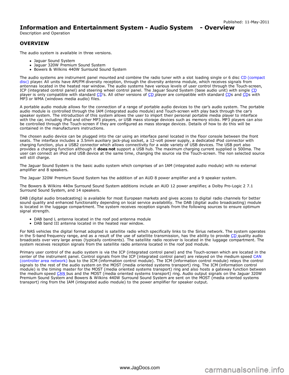
player is only compatible with standard CD's. All other versions of CD player are compatible with standard CDs and CDs with MP3 or WMA (windows media audio) files.
A portable audio module allows for the connection of a range of portable audio devices to the car’s audio system. The portable
audio module is controlled through the IAM (integrated audio module) and Touch-screen with play back through the car’s
speaker system. The introduction of this system allows the user to import their personal portable media player to interface
with the car, including iPod and other MP3 players, or USB mass storage devices such as memory sticks. MP3 players can also
be controlled through the Touch-screen if they are configured as mass storage devices. Details of how to do this will be
contained in the manufacturers instructions.
The chosen audio device can be plugged into the car using an interface panel located in the floor console between the front
seats. The interface includes a 3.5mm auxiliary jack-plug socket, a 12-volt power supply, a dedicated iPod connector with
charging function, plus a USB2 connector which allows connectivity for a wide variety of USB devices. The USB port also
provides a charging function although it does not support a USB hub. The maximum charging current supplied is 500ma. The
user can connect an iPod and USB device at the same time, changing the source via the Touch-screen. The non selected source
will still charge.
The Jaguar Sound System is the basic audio system which comprises of an IAM (integrated audio module) with no external
amplifier and 8 speakers.
The Jaguar 320W Premium Sound System has the addition of an AUD 8 power amplifier and a 9 speaker system.
The Bowers & Wilkins 440w Surround Sound System additions include an AUD 12 power amplifier, a Dolby Pro-Logic 2 7.1
Surround Sound System, and 14 speakers.
DAB (digital audio broadcasting) is available for most European markets and gives access to digital radio channels for better
sound quality and enhanced functionality depending on local service availability. The DAB (digital audio broadcasting) module
is located in the luggage compartment. The system receives reception signals from the following sources to ensure optimum
signal strength.
DAB band L antenna located in the roof pod antenna module
DAB band III antenna located in the heated rear window.
For NAS vehicles the digital format adopted is satellite radio which specifically links to the Sirius network. The system operates
in the S-band frequency range, and as a result of the use of satellite transmission, has the ability to provide CD quality audio broadcasts over very large areas (typically continents). The satellite radio receiver is located in the luggage compartment. The
system receives reception signals from the satellite radio antenna located in the roof pod module.
Primary user control of the audio system is via the ICP (integrated control panel) and the Touch-screen which are located in the
center of the instrument panel. Control signals from the ICP (integrated control panel) are relayed on the medium speed CAN
(controller area network) bus to the ICM (information control module). The ICM (information control module) relays the control
signals to the rest of the audio system on the MOST (media oriented systems transport) ring. The ICM (information control
module) is the timing master for the MOST (media oriented systems transport) ring and also hosts a gateway function between
the medium speed CAN bus and the MOST (media oriented systems transport) ring. Audio output signals on the Jaguar 320W Premium Sound System and Bowers & Wilkins 440W Surround Sound System are sent on the MOST (media oriented systems
transport) ring from the IAM (integrated audio module) to the power amplifier for speaker output. www.JagDocs.com
Page 1948 of 3039

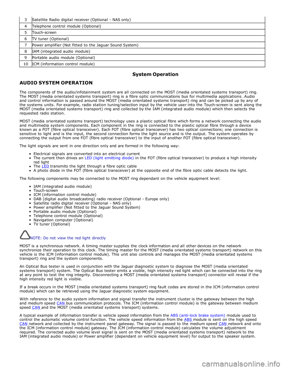
3 Satellite Radio digital receiver (Optional - NAS only) 4 Telephone control module (Optional) 5 Touch-screen 6 TV tuner (Optional) 7 Power amplifier (Not fitted to the Jaguar Sound System) 8 IAM (integrated audio module) 9 Portable audio module (Optional) 10 ICM (information control module)
AUDIO SYSTEM OPERATION System Operation
The components of the audio/infotainment system are all connected on the MOST (media orientated systems transport) ring.
The MOST (media orientated systems transport) ring is a fibre optic communications bus for multimedia applications. Audio
and control information is passed around the MOST (media orientated systems transport) ring and can be picked up by any of
the systems units. For example, radio station tuning/selection input by the vehicle user into the Touch-screen is sent along the
MOST (media orientated systems transport) ring and collected by the IAM (integrated audio module) which then selects the
requested radio station.
MOST (media orientated systems transport) technology uses a plastic optical fibre which forms a network connecting the audio
and multimedia system components. Each component in the ring is connected to the plastic optical fibre through a device
known as a FOT (fibre optical transceiver). Each FOT (fibre optical transceiver) has two optical connections; one connection is
sensitive to light and is the input, the second connection forms the light source and is the output. The system operates by
connecting the output from one FOT (fibre optical transceiver) to the input of another FOT (fibre optical transceiver).
The light signals are sent in one direction only and are formed in the following way:
Electrical signals are converted into an electrical current
The current then drives an LED (light emitting diode) in the FOT (fibre optical transceiver) to produce a high intensity
red light
The LED transmits the light through a fibre optic cable A photo diode in the FOT (fibre optical transceiver) at the opposite end of the fibre optic cable detects the light.
The following components may be connected to the MOST ring dependant on the vehicle equipment level:
IAM (integrated audio module)
Touch-screen
ICM (information control module)
DAB (digital audio broadcasting) radio receiver (Optional - Europe only)
Satellite radio digital receiver (Optional - NAS only)
Power amplifier (Not fitted to the Jaguar Sound System)
Portable audio module (Optional)
Telephone control module (Optional)
Navigation computer (Optional)
TV tuner (Optional)
NOTE: Do not view the red light directly
MOST is a synchronous network. A timing master supplies the clock information and all other devices on the network
synchronize their operation to this clock. The timing master for the MOST (media orientated systems transport) network on this
vehicle is the ICM (information control module). This unit also controls and manages the MOST (media orientated systems
transport) ring and the system components.
An Optical Bus tester is used in conjunction with the Jaguar diagnostic system to diagnose the MOST (media orientated
systems transport) system. The Optical Bus tester emits a visible, high intensity red light which can be connected into the ring
at any point to test the ring integrity. Disconnecting a MOST (media orientated systems transport) connector will reveal if the
high intensity red light is visible.
If a break occurs in the MOST (media orientated systems transport) ring fault codes are stored in the ICM (information control
module) which can be retrieved using the Jaguar diagnostic system equipment.
With reference to the audio system information and signal transfer the instrument cluster is the gateway between the high
and medium speed CAN bus communication protocols. The ICM (information control module) is the gateway between medium speed CAN and the MOST (media orientated systems transport) systems.
A typical example of information transfer is vehicle speed information from the ABS (anti-lock brake system) module used to
control the automatic volume control function. The vehicle speed information from the ABS module is sent on the high speed CAN network and collected by the instrument panel gateway. The signal is passed to the medium speed CAN network and onto the ICM (information control module) gateway. The ICM (information control module) calculates the volume adjustment
required. The corrected audio volume level signal is sent on the MOST (media orientated systems transport) network to the
IAM (integrated audio module) or Power amplifier (dependant on vehicle equipment level) for output to the speaker system.
Page 1953 of 3039

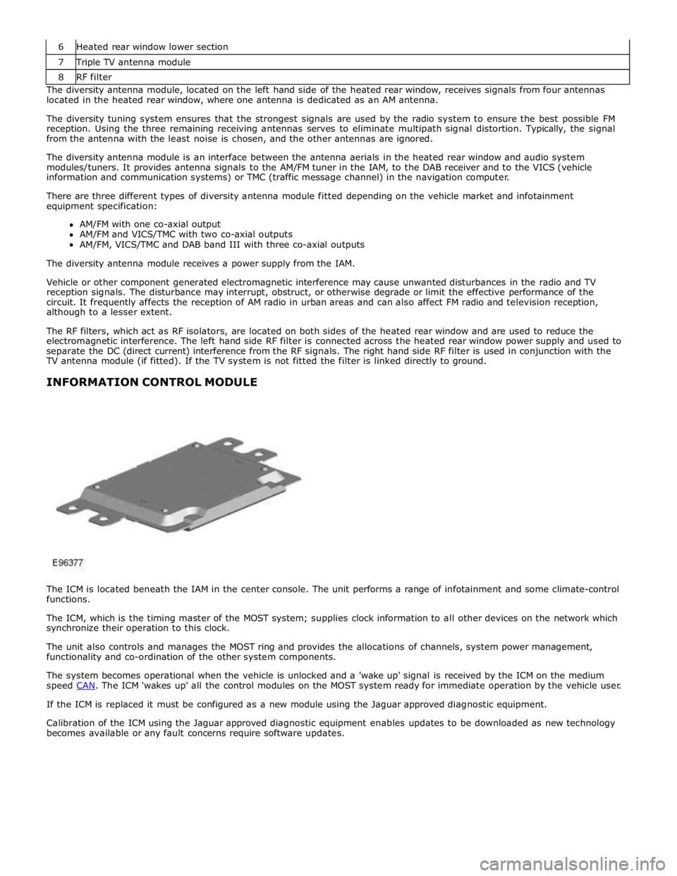
7 Triple TV antenna module 8 RF filter The diversity antenna module, located on the left hand side of the heated rear window, receives signals from four antennas
located in the heated rear window, where one antenna is dedicated as an AM antenna.
The diversity tuning system ensures that the strongest signals are used by the radio system to ensure the best possible FM
reception. Using the three remaining receiving antennas serves to eliminate multipath signal distortion. Typically, the signal
from the antenna with the least noise is chosen, and the other antennas are ignored.
The diversity antenna module is an interface between the antenna aerials in the heated rear window and audio system
modules/tuners. It provides antenna signals to the AM/FM tuner in the IAM, to the DAB receiver and to the VICS (vehicle
information and communication systems) or TMC (traffic message channel) in the navigation computer.
There are three different types of diversity antenna module fitted depending on the vehicle market and infotainment
equipment specification:
AM/FM with one co-axial output
AM/FM and VICS/TMC with two co-axial outputs
AM/FM, VICS/TMC and DAB band III with three co-axial outputs
The diversity antenna module receives a power supply from the IAM.
Vehicle or other component generated electromagnetic interference may cause unwanted disturbances in the radio and TV
reception signals. The disturbance may interrupt, obstruct, or otherwise degrade or limit the effective performance of the
circuit. It frequently affects the reception of AM radio in urban areas and can also affect FM radio and television reception,
although to a lesser extent.
The RF filters, which act as RF isolators, are located on both sides of the heated rear window and are used to reduce the
electromagnetic interference. The left hand side RF filter is connected across the heated rear window power supply and used to
separate the DC (direct current) interference from the RF signals. The right hand side RF filter is used in conjunction with the
TV antenna module (if fitted). If the TV system is not fitted the filter is linked directly to ground.
INFORMATION CONTROL MODULE
The ICM is located beneath the IAM in the center console. The unit performs a range of infotainment and some climate-control
functions.
The ICM, which is the timing master of the MOST system; supplies clock information to all other devices on the network which
synchronize their operation to this clock.
The unit also controls and manages the MOST ring and provides the allocations of channels, system power management,
functionality and co-ordination of the other system components.
The system becomes operational when the vehicle is unlocked and a 'wake up' signal is received by the ICM on the medium
speed CAN. The ICM 'wakes up' all the control modules on the MOST system ready for immediate operation by the vehicle user. If the ICM is replaced it must be configured as a new module using the Jaguar approved diagnostic equipment.
Calibration of the ICM using the Jaguar approved diagnostic equipment enables updates to be downloaded as new technology
becomes available or any fault concerns require software updates.