2010 JAGUAR XFR Timing
[x] Cancel search: TimingPage 1363 of 3039
Defaults to base mapping for the ignition timing, with no cylinder correction
Disables the VCT system.
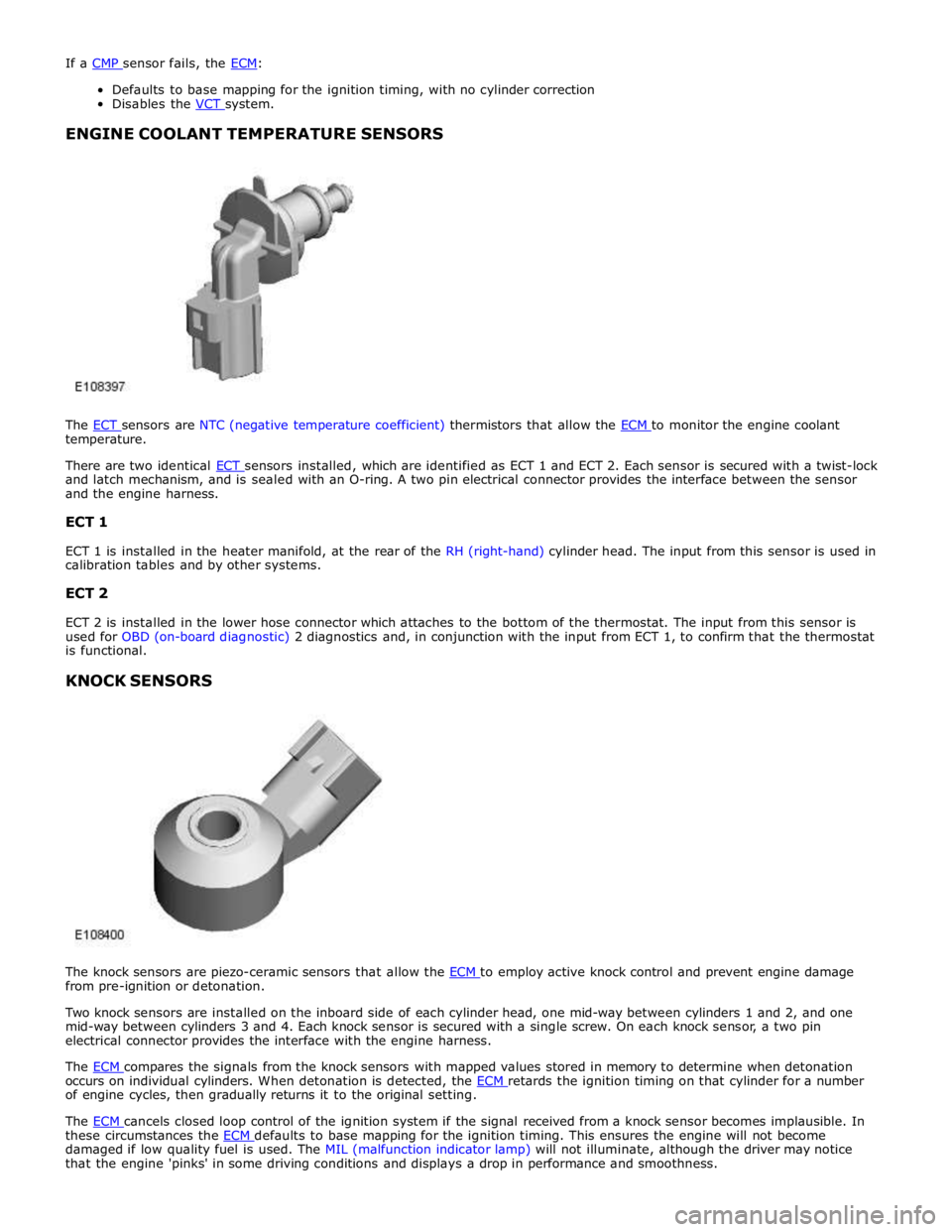
ENGINE COOLANT TEMPERATURE SENSORS
The ECT sensors are NTC (negative temperature coefficient) thermistors that allow the ECM to monitor the engine coolant temperature.
There are two identical ECT sensors installed, which are identified as ECT 1 and ECT 2. Each sensor is secured with a twist-lock and latch mechanism, and is sealed with an O-ring. A two pin electrical connector provides the interface between the sensor
and the engine harness.
ECT 1
ECT 1 is installed in the heater manifold, at the rear of the RH (right-hand) cylinder head. The input from this sensor is used in
calibration tables and by other systems.
ECT 2
ECT 2 is installed in the lower hose connector which attaches to the bottom of the thermostat. The input from this sensor is
used for OBD (on-board diagnostic) 2 diagnostics and, in conjunction with the input from ECT 1, to confirm that the thermostat
is functional.
KNOCK SENSORS
The knock sensors are piezo-ceramic sensors that allow the ECM to employ active knock control and prevent engine damage from pre-ignition or detonation.
Two knock sensors are installed on the inboard side of each cylinder head, one mid-way between cylinders 1 and 2, and one
mid-way between cylinders 3 and 4. Each knock sensor is secured with a single screw. On each knock sensor, a two pin
electrical connector provides the interface with the engine harness.
The ECM compares the signals from the knock sensors with mapped values stored in memory to determine when detonation occurs on individual cylinders. When detonation is detected, the ECM retards the ignition timing on that cylinder for a number of engine cycles, then gradually returns it to the original setting.
The ECM cancels closed loop control of the ignition system if the signal received from a knock sensor becomes implausible. In these circumstances the ECM defaults to base mapping for the ignition timing. This ensures the engine will not become damaged if low quality fuel is used. The MIL (malfunction indicator lamp) will not illuminate, although the driver may notice
that the engine 'pinks' in some driving conditions and displays a drop in performance and smoothness.
Page 1365 of 3039
MANIFOLD ABSOLUTE PRESSURE AND TEMPERATURE SENSOR
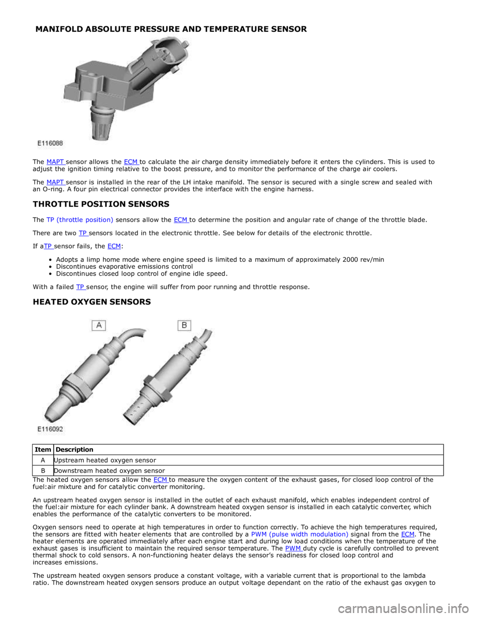
The MAPT sensor allows the ECM to calculate the air charge density immediately before it enters the cylinders. This is used to adjust the ignition timing relative to the boost pressure, and to monitor the performance of the charge air coolers.
The MAPT sensor is installed in the rear of the LH intake manifold. The sensor is secured with a single screw and sealed with an O-ring. A four pin electrical connector provides the interface with the engine harness.
THROTTLE POSITION SENSORS
The TP (throttle position) sensors allow the ECM to determine the position and angular rate of change of the throttle blade. There are two TP sensors located in the electronic throttle. See below for details of the electronic throttle. If aTP sensor fails, the ECM:
Adopts a limp home mode where engine speed is limited to a maximum of approximately 2000 rev/min
Discontinues evaporative emissions control
Discontinues closed loop control of engine idle speed.
With a failed TP sensor, the engine will suffer from poor running and throttle response.
HEATED OXYGEN SENSORS
Item Description A Upstream heated oxygen sensor B Downstream heated oxygen sensor The heated oxygen sensors allow the ECM to measure the oxygen content of the exhaust gases, for closed loop control of the fuel:air mixture and for catalytic converter monitoring.
An upstream heated oxygen sensor is installed in the outlet of each exhaust manifold, which enables independent control of
the fuel:air mixture for each cylinder bank. A downstream heated oxygen sensor is installed in each catalytic converter, which
enables the performance of the catalytic converters to be monitored.
Oxygen sensors need to operate at high temperatures in order to function correctly. To achieve the high temperatures required,
the sensors are fitted with heater elements that are controlled by a PWM (pulse width modulation) signal from the ECM. The heater elements are operated immediately after each engine start and during low load conditions when the temperature of the
exhaust gases is insufficient to maintain the required sensor temperature. The PWM duty cycle is carefully controlled to prevent thermal shock to cold sensors. A non-functioning heater delays the sensor’s readiness for closed loop control and
increases emissions.
The upstream heated oxygen sensors produce a constant voltage, with a variable current that is proportional to the lambda
ratio. The downstream heated oxygen sensors produce an output voltage dependant on the ratio of the exhaust gas oxygen to
Page 1371 of 3039

Symptom Possible Cause Action Engine stalls on overrun
ECM relay
Throttle position (TP)
sensors
Read DTCs and refer to DTC Index in this
section for ECM relay and TP sensor tests Engine stalls at steady speed
ECM relay
crankshaft position sensor
TP sensors
Read DTCs and refer to DTC Index in this
section for ECM relay, crankshaft position
sensor, and TP sensor tests Engine stalls with speed control
enabled
ECM relay
Read DTCs and refer to DTC Index in this
section for ECM relay tests Engine stalls when manoeuvring
ECM relay
TP sensors
Additional engine loads
(PAS, air conditioning, etc)
Transmission malfunction
CAN malfunction
Read DTCs and refer to DTC Index in this
section for ECM relay, and TP sensor tests
Check for excessive loads being placed on
the engine from PAS, air conditioning
systems etc.
Refer to the workshop manual or
transmission troubleshooting guide for
transmission system tests.
Refer to the relevant section of the
workshop manual and the electrical wiring
diagrams to perform CAN network tests. Poor driveability Engine hesitates/poor acceleration
Fuel pressure, fuel pump,
fuel lines
Injector leak
Air leakage
Electronic engine controls
Ignition system
EGR valve stuck
Transmission malfunction
Restricted pedal travel
(carpet, etc)
For fuel system tests refer to the relevant
section of the workshop manual
Carry out fuel injector leak tests, install new
injectors as necessary.
Check for leakage from air intake system
Read DTCs and refer to DTC Index in this
section for electronic engine control tests
For ignition system tests refer to the
relevant section of the workshop manual
Refer to the relevant section of the
workshop manual and check the Exhaust Gas
Recirculation (EGR) valve and associated
hoses and connections.
Refer to the workshop manual or
transmission troubleshooting guide for
transmission system tests.
Ensure accelerator pedal is free from
restriction Engine backfires
Fuel pump, fuel lines
Air leakage
Electronic engine controls
Ignition system
Sticking variable camshaft
timing (VCT) hub
For fuel system tests refer to the relevant
section of the workshop manual
Check for leakage from air intake system
Read DTCs and refer to DTC Index in this
section for electronic engine control tests
For ignition system tests refer to the
relevant section of the workshop manual
Read DTCs and refer to DTC Index in this
section for VCT system tests Engine surges
Fuel pump, fuel lines
Electronic engine controls
Ignition system
For fuel system tests refer to the relevant
section of the workshop manual
Read DTCs and refer to DTC Index in this
section for electronic engine control tests
For ignition system tests refer to the
relevant section of the workshop manual Engine detonates/knocks
Electronic engine controls
Fuel pump, fuel lines, fuel
quality
Air leakage
Sticking VCT hub
Read DTCs and refer to DTC Index in this
section for electronic engine control tests
For fuel system tests refer to the relevant
section of the workshop manual
Check for leakage from air intake system
Read DTCs and refer to DTC Index in this
section for VCT system tests www.JagDocs.com
Page 1404 of 3039
Published: 11-May-2011
Electronic Engine Controls - V8 S/C 5.0L Petrol - Variable Valve Timing (VVT)
Oil Control Solenoid LH
Removal and Installation
Removal
NOTE: Removal steps in this procedure may contain installation details.
1. Disconnect the battery ground cable.
Refer to: Specifications (414-00, Specifications).
2. WARNING: Make sure to support the vehicle with axle stands.
Raise and support the vehicle.
3. Refer to: Thermostat Housing - Vehicles With: Supercharger (303-03,
Removal and Installation).
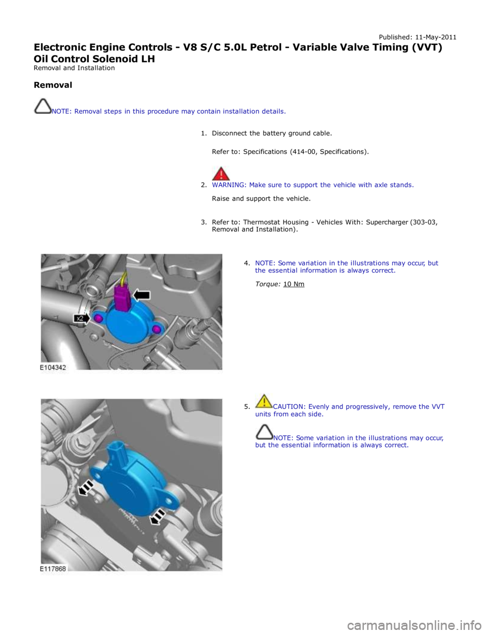
4. NOTE: Some variation in the illustrations may occur, but
the essential information is always correct.
Torque: 10 Nm
5. CAUTION: Evenly and progressively, remove the VVT
units from each side.
NOTE: Some variation in the illustrations may occur,
but the essential information is always correct.
Page 1406 of 3039
Published: 11-May-2011
Electronic Engine Controls - V8 S/C 5.0L Petrol - Variable Valve Timing (VVT)
Oil Control Solenoid RH
Removal and Installation
Removal
NOTE: Removal steps in this procedure may contain installation details.
1. Disconnect the battery ground cable.
Refer to: Specifications (414-00, Specifications).
2. WARNING: Make sure to support the vehicle with axle stands.
Raise and support the vehicle.
3. Refer to: Thermostat Housing - Vehicles With: Supercharger (303-03,
Removal and Installation).
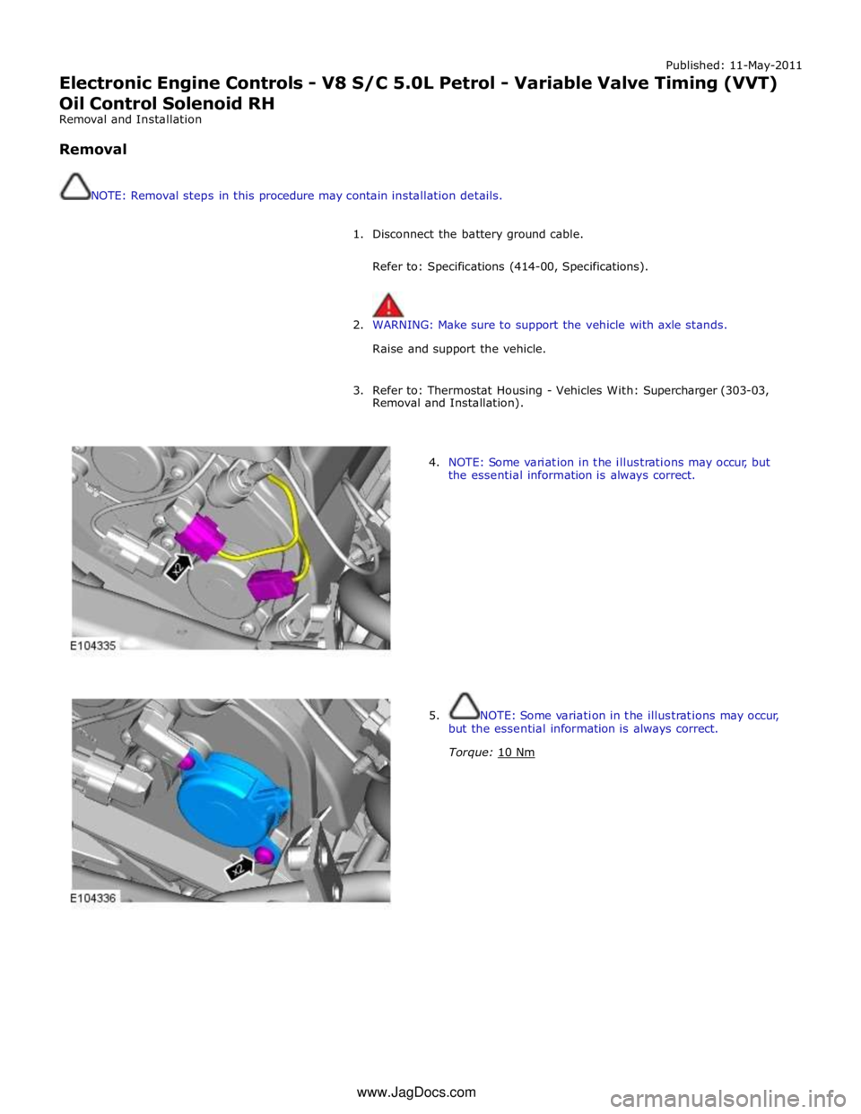
4. NOTE: Some variation in the illustrations may occur, but
the essential information is always correct.
5. NOTE: Some variation in the illustrations may occur,
but the essential information is always correct.
Torque: 10 Nm www.JagDocs.com
Page 1431 of 3039
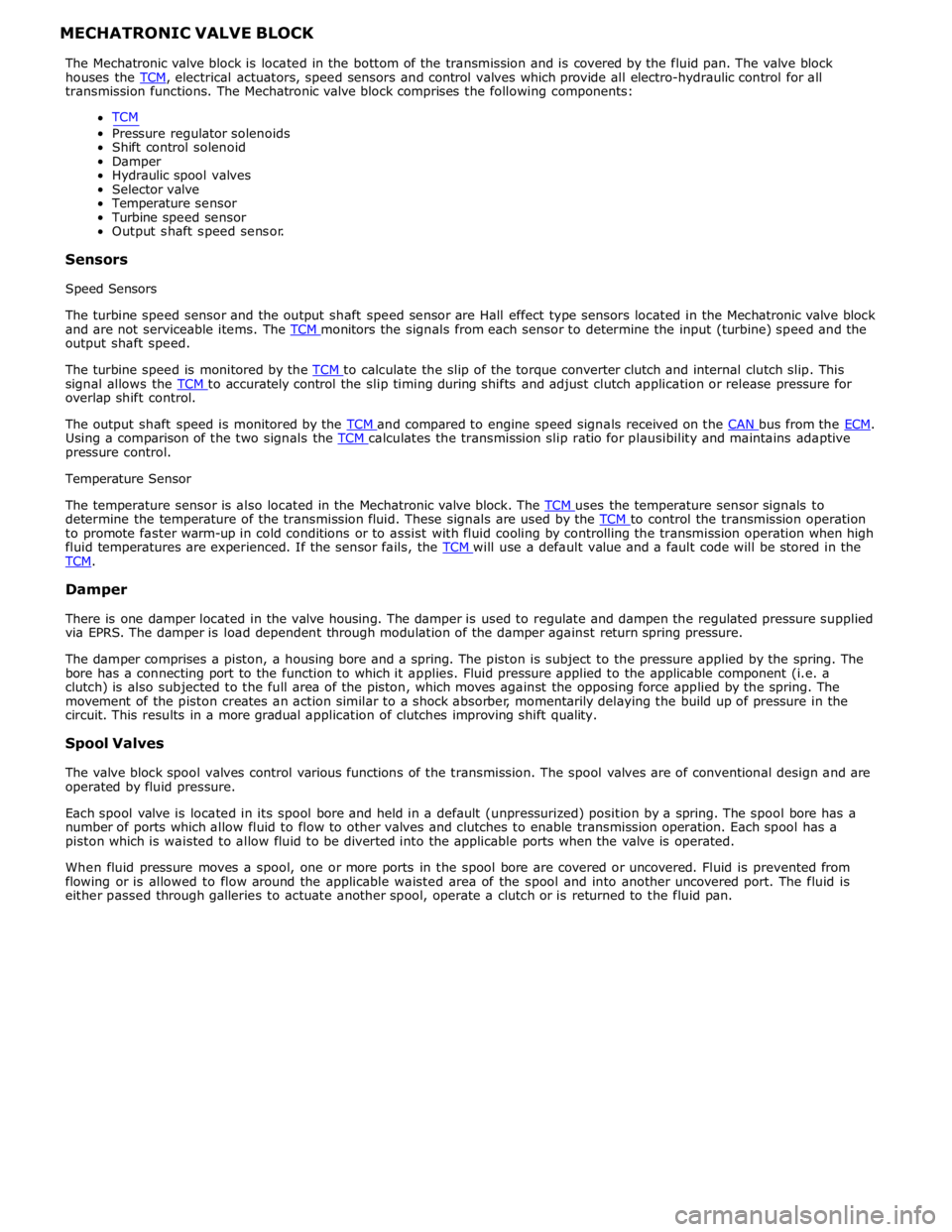
transmission functions. The Mechatronic valve block comprises the following components:
TCM
Pressure regulator solenoids
Shift control solenoid
Damper
Hydraulic spool valves
Selector valve
Temperature sensor
Turbine speed sensor
Output shaft speed sensor.
Sensors
Speed Sensors
The turbine speed sensor and the output shaft speed sensor are Hall effect type sensors located in the Mechatronic valve block
and are not serviceable items. The TCM monitors the signals from each sensor to determine the input (turbine) speed and the output shaft speed.
The turbine speed is monitored by the TCM to calculate the slip of the torque converter clutch and internal clutch slip. This signal allows the TCM to accurately control the slip timing during shifts and adjust clutch application or release pressure for overlap shift control.
The output shaft speed is monitored by the TCM and compared to engine speed signals received on the CAN bus from the ECM. Using a comparison of the two signals the TCM calculates the transmission slip ratio for plausibility and maintains adaptive pressure control.
Temperature Sensor
The temperature sensor is also located in the Mechatronic valve block. The TCM uses the temperature sensor signals to determine the temperature of the transmission fluid. These signals are used by the TCM to control the transmission operation to promote faster warm-up in cold conditions or to assist with fluid cooling by controlling the transmission operation when high
fluid temperatures are experienced. If the sensor fails, the TCM will use a default value and a fault code will be stored in the TCM.
Damper
There is one damper located in the valve housing. The damper is used to regulate and dampen the regulated pressure supplied
via EPRS. The damper is load dependent through modulation of the damper against return spring pressure.
The damper comprises a piston, a housing bore and a spring. The piston is subject to the pressure applied by the spring. The
bore has a connecting port to the function to which it applies. Fluid pressure applied to the applicable component (i.e. a
clutch) is also subjected to the full area of the piston, which moves against the opposing force applied by the spring. The
movement of the piston creates an action similar to a shock absorber, momentarily delaying the build up of pressure in the
circuit. This results in a more gradual application of clutches improving shift quality.
Spool Valves
The valve block spool valves control various functions of the transmission. The spool valves are of conventional design and are
operated by fluid pressure.
Each spool valve is located in its spool bore and held in a default (unpressurized) position by a spring. The spool bore has a
number of ports which allow fluid to flow to other valves and clutches to enable transmission operation. Each spool has a
piston which is waisted to allow fluid to be diverted into the applicable ports when the valve is operated.
When fluid pressure moves a spool, one or more ports in the spool bore are covered or uncovered. Fluid is prevented from
flowing or is allowed to flow around the applicable waisted area of the spool and into another uncovered port. The fluid is
either passed through galleries to actuate another spool, operate a clutch or is returned to the fluid pan.
Page 1597 of 3039
Symptom Possible Causes Action Electronic engine control
Throttle motor
Restricted accelerator pedal
travel (carpet, etc)
Ignition system
Transmission malfunction Check for air leakage in air intake system
Ensure accelerator pedal is free from restriction
Check for electronic engine controls, ignition, engine
emission system and transmission related DTCs and
refer to the relevant DTC Index Engine backfires
Fuel pump/lines
Air leakage
Electronic engine controls
Ignition system
Sticking variable camshaft
timing (VCT) hub
Check for fuel system failures
Check for air leakage in intake air system
Check for electronic engine controls, ignition system
and VCT system related DTCs and refer to the
relevant DTC Index Engine surges
Fuel pump/lines
Electronic engine controls
Throttle motor
Ignition system
Check for fuel system failures
Check for electronic engine controls, throttle system
and ignition system related DTCs and refer to the
relevant DTC Index Engine detonates/knocks
Fuel pump/lines
Air leakage
Electronic engine controls
Sticking VCT hub
Check for fuel system failures
Check for air leakage in intake air system
Check for electronic engine controls and VCT system
related DTCs and refer to the relevant DTC Index No throttle response
Electronic engine controls
Throttle motor
Check for electronic engine controls and throttle
system related DTCs and refer to the relevant DTC
Index Poor throttle response
Breather system
disconnected/restricted
Electronic engine controls
Transmission malfunction
Traction control event
Air leakage
Ensure the engine breather system is free from
restriction and is correctly installed
Check for electronic engine controls, transmission
and traction control related DTCs and refer to the
related DTC Index
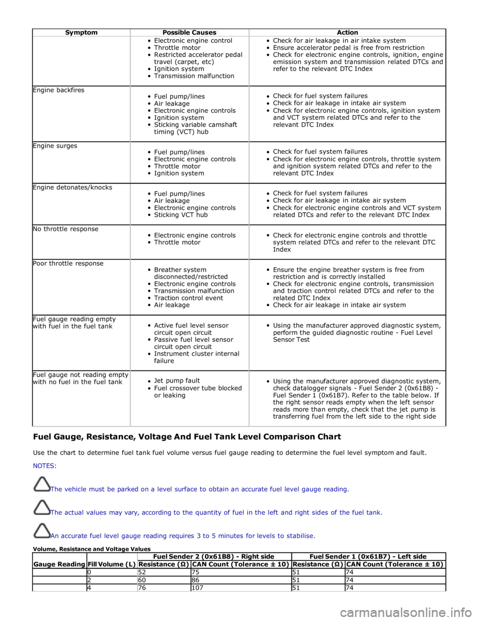
Check for air leakage in intake air system Fuel gauge reading empty
with fuel in the fuel tank
Active fuel level sensor
circuit open circuit
Passive fuel level sensor
circuit open circuit
Instrument cluster internal
failure
Using the manufacturer approved diagnostic system,
perform the guided diagnostic routine - Fuel Level
Sensor Test Fuel gauge not reading empty
with no fuel in the fuel tank
Jet pump fault
Fuel crossover tube blocked
or leaking
Using the manufacturer approved diagnostic system,
check datalogger signals - Fuel Sender 2 (0x61B8) -
Fuel Sender 1 (0x61B7). Refer to the table below. If
the right sensor reads empty when the left sensor
reads more than empty, check that the jet pump is
transferring fuel from the left side to the right side Fuel Gauge, Resistance, Voltage And Fuel Tank Level Comparison Chart
Use the chart to determine fuel tank fuel volume versus fuel gauge reading to determine the fuel level symptom and fault.
NOTES:
The vehicle must be parked on a level surface to obtain an accurate fuel level gauge reading.
The actual values may vary, according to the quantity of fuel in the left and right sides of the fuel tank.
An accurate fuel level gauge reading requires 3 to 5 minutes for levels to stabilise.
Volume, Resistance and Voltage Values
Gauge Reading
Fill Volume (L) Fuel Sender 2 (0x61B8) - Right side Fuel Sender 1 (0x61B7) - Left side Resistance (Ω) CAN Count (Tolerance ± 10) Resistance (Ω) CAN Count (Tolerance ± 10) 0 52 75 51 74 2 60 86 51 74 4 76 107 51 74
Page 1641 of 3039
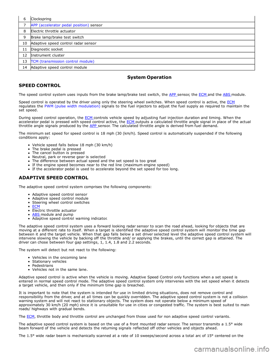
6 Clockspring 7 APP (accelerator pedal position) sensor 8 Electric throttle actuator 9 Brake lamp/brake test switch 10 Adaptive speed control radar sensor 11 Diagnostic socket 12 Instrument cluster 13 TCM (transmission control module) 14 Adaptive speed control module
SPEED CONTROL System Operation
The speed control system uses inputs from the brake lamp/brake test switch, the APP sensor, the ECM and the ABS module.
Speed control is operated by the driver using only the steering wheel switches. When speed control is active, the ECM regulates the PWM (pulse width modulation) signals to the fuel injectors to adjust the fuel supply as required to maintain the
set speed.
During speed control operation, the ECM controls vehicle speed by adjusting fuel injection duration and timing. When the accelerator pedal is pressed with speed control active, the ECM outputs a calculated throttle angle signal in place of the actual throttle angle signals produced by the APP sensor. The calculated throttle angle is derived from fuel demand.
The minimum set speed for speed control is 18 mph (30 (km/h). Speed control is automatically suspended if the following
conditions apply:
Vehicle speed falls below 18 mph (30 km/h)
The brake pedal is pressed
The cancel button is pressed
Neutral, park or reverse gear is selected
The difference between actual speed and the set speed is too great
If the engine speed becomes near to the red line (maximum engine speed)
If the accelerator pedal is used to accelerate beyond the set speed for too long.
ADAPTIVE SPEED CONTROL
The adaptive speed control system comprises the following components:
Adaptive speed control sensor
Adaptive speed control module
Steering wheel control switches
ECM
Electric throttle actuator
ABS module and pump Adaptive speed control warning indicator.
The adaptive speed control system uses a forward looking radar sensor to scan the road ahead, looking for objects that are
moving at a different rate to itself. When a target is identified the adaptive speed control system will monitor the time gap
between it and the target vehicle. When that gap falls below a set driver selected level the adaptive speed control system will
intervene slowing the vehicle by backing off the throttle and/ or applying the brakes, until the correct gap is attained. The
driver can chose between four gap settings, 1, 1.4, 1.8 and 2.2 seconds.
The system will detect but not react to the following:
Vehicles in the oncoming lane
Stationary vehicles
Pedestrians
Vehicles not in the same lane.
Adaptive speed control is active when the vehicle is moving. Adaptive Speed Control only functions when a set speed is
entered in normal speed control mode. The adaptive speed control system only intervenes with the set speed when it detects
a target vehicle, and then only if the minimum time gap is breached.
It is important to note that the system is intended for use in limited driving situations, does not remove control and
responsibility from the driver, and at all times can be quickly overridden. The adaptive speed control system is not a collision
warning system and will not react to stationary objects. The system does not operate below a minimum speed of
approximately 30 km/h (20 mph) since it is unsuitable for use in cities or congested traffic. The system is best suited to main
roads/ highways with gradual bends.
The ECM, throttle body and throttle control are unchanged from those used for non adaptive speed control variants.
The adaptive speed control system is based on the use of a front mounted radar sensor. The sensor transmits a 1.5° wide
beam forward of the vehicle and detects the returning signals reflected off other vehicles and objects ahead.
The 1.5° wide radar beam is mechanically scanned at a rate of 10 sweeps/second across a total arc of 15° centered on the