2010 JAGUAR XFR Timing
[x] Cancel search: TimingPage 1076 of 3039
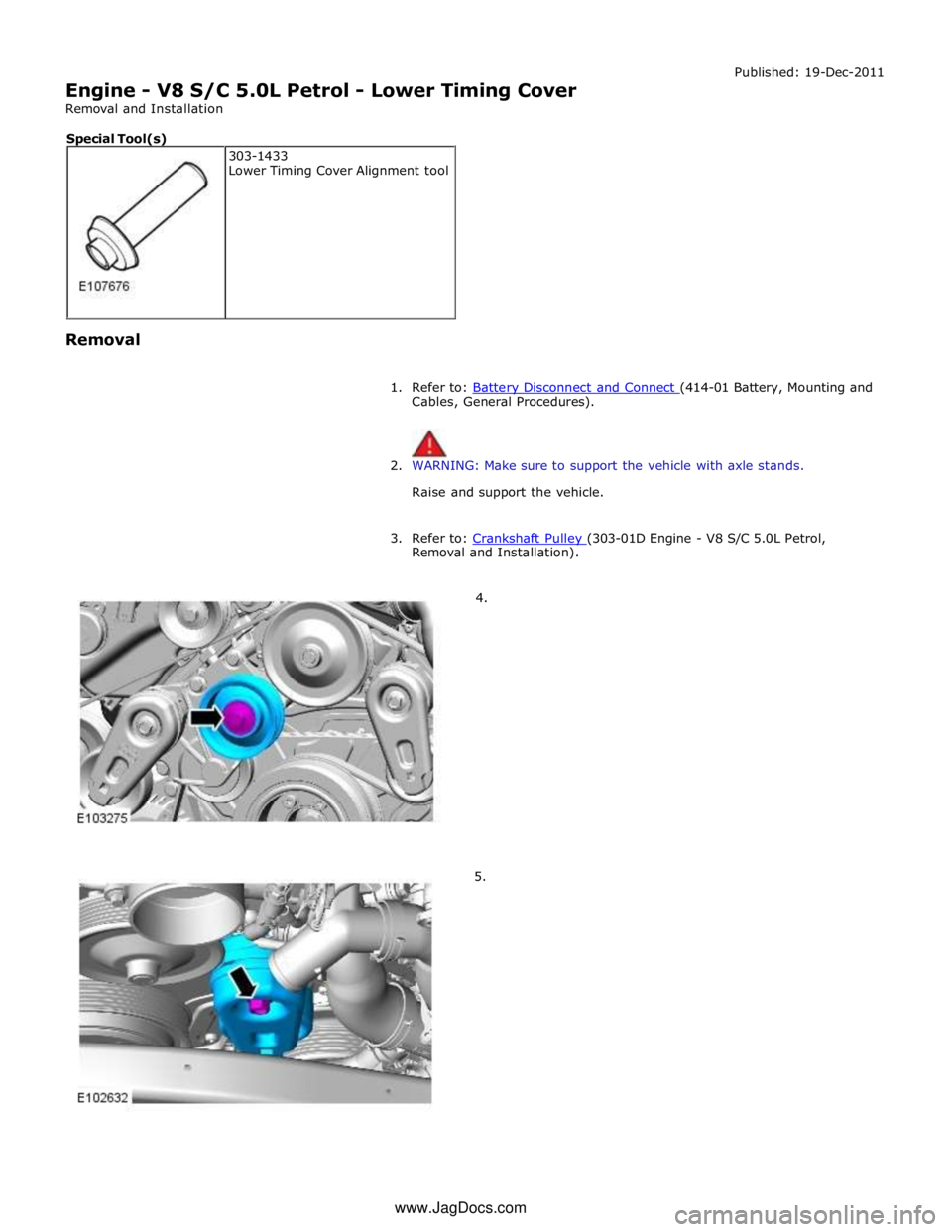
Engine - V8 S/C 5.0L Petrol - Lower Timing Cover
Removal and Installation Published: 19-Dec-2011
Removal
1. Refer to: Battery Disconnect and Connect (414-01 Battery, Mounting and Cables, General Procedures).
2. WARNING: Make sure to support the vehicle with axle stands.
Raise and support the vehicle.
3. Refer to: Crankshaft Pulley (303-01D Engine - V8 S/C 5.0L Petrol, Removal and Installation).
4.
5. 303-1433
Lower Timing Cover Alignment tool Special Tool(s) www.JagDocs.com
Page 1181 of 3039
to deliver the correct mass of fuel to the combustion chambers.
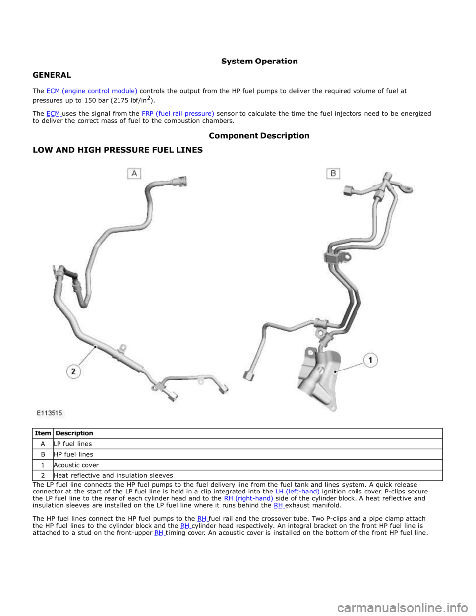
LOW AND HIGH PRESSURE FUEL LINES Component Description
Item Description A LP fuel lines B HP fuel lines 1 Acoustic cover 2 Heat reflective and insulation sleeves The LP fuel line connects the HP fuel pumps to the fuel delivery line from the fuel tank and lines system. A quick release
connector at the start of the LP fuel line is held in a clip integrated into the LH (left-hand) ignition coils cover. P-clips secure
the LP fuel line to the rear of each cylinder head and to the RH (right-hand) side of the cylinder block. A heat reflective and
insulation sleeves are installed on the LP fuel line where it runs behind the RH exhaust manifold.
The HP fuel lines connect the HP fuel pumps to the RH fuel rail and the crossover tube. Two P-clips and a pipe clamp attach the HP fuel lines to the cylinder block and the RH cylinder head respectively. An integral bracket on the front HP fuel line is attached to a stud on the front-upper RH timing cover. An acoustic cover is installed on the bottom of the front HP fuel line.
Page 1188 of 3039

Symptom Possible Causes Action Purge valve
Difficult hot start
Injector leak
Electronic engine control
Purge valve
Fuel pump
Ignition system
EGR valve stuck open Check for injector leak, install new injector as required.
Check for electronic engine controls, evaporative emissions,
fuel system, ignition system and engine emission system
related DTCs and refer to the relevant DTC Index Difficult to start after hot
soak (vehicle standing,
engine off, after engine has
reached operating
temperature)
Injector leak
Electronic engine control
Purge valve
Fuel pump
Ignition system
EGR valve stuck open Check for injector leak, install new injector as required.
Check for electronic engine controls, evaporative emissions,
fuel system, ignition system and engine emission system
related DTCs and refer to the relevant DTC Index Engine stalls soon after start
Breather system
disconnected/restricted
ECM relay
Electronic engine control
Ignition system
Air intake system restricted
Air leakage
Fuel lines Ensure the engine breather system is free from restriction
and is correctly installed. Check for electronic engine
control, ignition system and fuel system related DTCs and
refer to the relevant DTC Index. Check for blockage in air
filter element and air intake system. Check for air leakage
in air intake system Engine hesitates/poor
acceleration
Fuel pressure, fuel pump,
fuel lines
Injector leak
Air leakage
Electronic engine control
Throttle motor
Restricted accelerator pedal
travel (carpet, etc)
Ignition system
EGR valve stuck open
Transmission malfunction Check for fuel system related DTCs and refer to the
relevant DTC Index. Check for injector leak, install new
injector as required. Check for air leakage in air intake
system. Ensure accelerator pedal is free from restriction.
Check for electronic engine controls, ignition, engine
emission system and transmission related DTCs and refer
to the relevant DTC Index Engine backfires
Fuel pump/lines
Air leakage
Electronic engine controls
Ignition system
Sticking variable camshaft
timing (VCT) hub Check for fuel system failures. Check for air leakage in
intake air system. Check for electronic engine controls,
ignition system and VCT system related DTCs and refer to
the relevant DTC Index Engine surges
Fuel pump/lines
Electronic engine controls
Throttle motor
Ignition system Check for fuel system failures. Check for electronic engine
controls, throttle system and ignition system related DTCs
and refer to the relevant DTC Index Engine detonates/knocks
Fuel pump/lines
Air leakage
Electronic engine controls
Sticking VCT hub Check for fuel system failures. Check for air leakage in
intake air system. Check for electronic engine controls and
VCT system related DTCs and refer to the relevant DTC
Index No throttle response
Electronic engine controls
Throttle motor Check for electronic engine controls and throttle system
related DTCs and refer to the relevant DTC Index Poor throttle response
Breather system
disconnected/restricted
Electronic engine control
Transmission malfunction
Traction control event Air
leakage Ensure the engine breather system is free from restriction
and is correctly installed. Check for electronic engine
controls, transmission and traction control related DTCs and
refer to the related DTC Index. Check for air leakage in
intake air system DTC Index
For a list of Diagnostic Trouble Codes (DTCs) that could be logged in the Engine Control Module (ECM), please refer to Section
303-14.
REFER to: Electronic Engine Controls (303-14C Electronic Engine Controls - V8 5.0L Petrol, Diagnosis and Testing) / Electronic Engine Controls (303-14D Electronic Engine Controls - V8 S/C 5.0L Petrol, Diagnosis and Testing).
Page 1274 of 3039
GENERAL System Operation
The ignition coils are supplied with electrical power from the battery via a 250 A megafuse in the BJB (battery junction box)
and the ignition relay in the EJB (engine junction box). The control signal for the ignition relay is supplied by the CJB (central
junction box).
The ECM (engine control module) sends a separate signal to each ignition coil to trigger the power stage switching. The ECM calculates the dwell time from the battery voltage and engine speed, to ensure a constant energy level is produced in the
secondary coil each time the power stage is switched. This ensures sufficient spark energy is available without excessive
primary current flow, which avoids overheating and damage to the ignition coils.
The ECM calculates the ignition timing for individual cylinders from: Engine speed
Camshaft position
Engine load
Engine temperature
The knock control function
The shift control function
The idle speed control function.
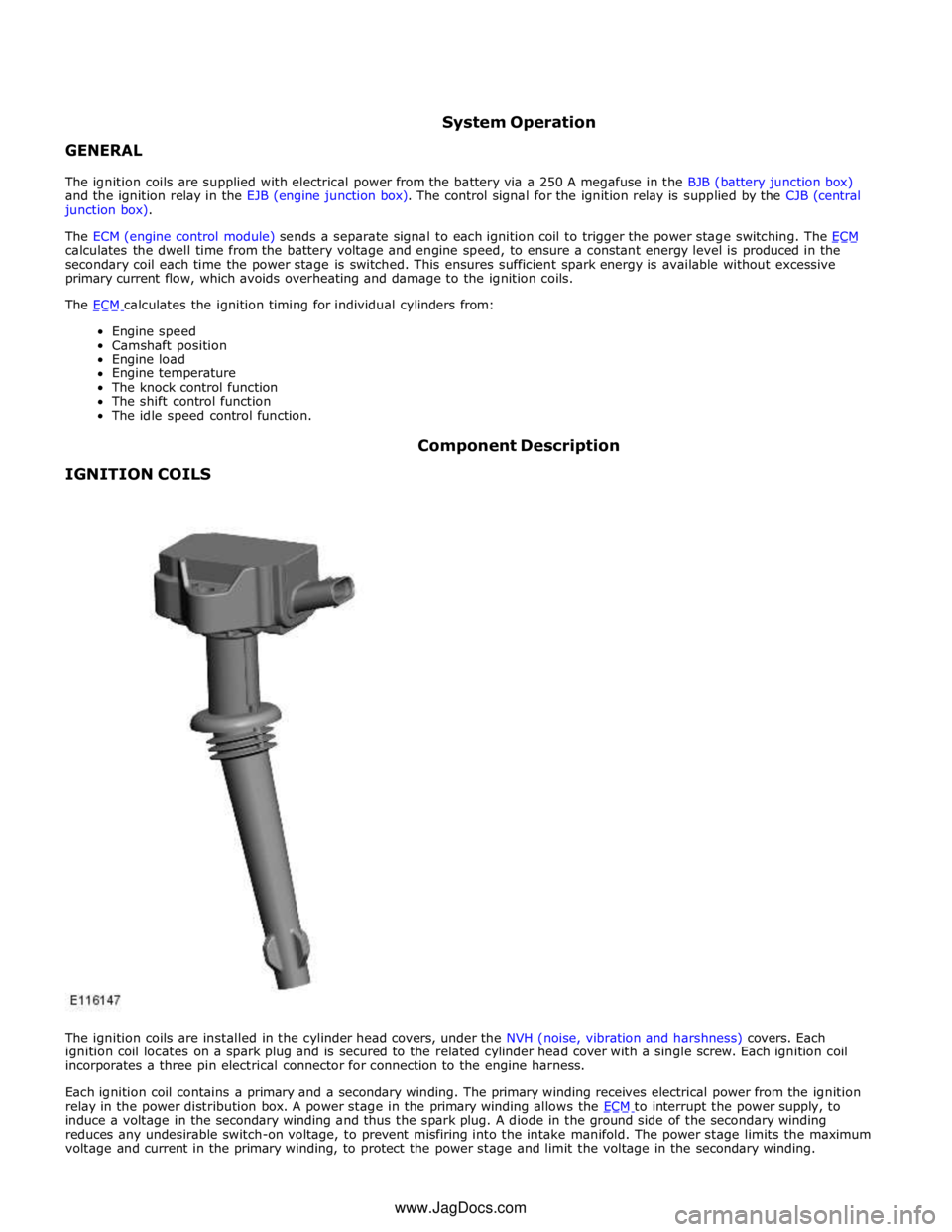
IGNITION COILS Component Description
The ignition coils are installed in the cylinder head covers, under the NVH (noise, vibration and harshness) covers. Each
ignition coil locates on a spark plug and is secured to the related cylinder head cover with a single screw. Each ignition coil
incorporates a three pin electrical connector for connection to the engine harness.
Each ignition coil contains a primary and a secondary winding. The primary winding receives electrical power from the ignition
relay in the power distribution box. A power stage in the primary winding allows the ECM to interrupt the power supply, to induce a voltage in the secondary winding and thus the spark plug. A diode in the ground side of the secondary winding
reduces any undesirable switch-on voltage, to prevent misfiring into the intake manifold. The power stage limits the maximum
voltage and current in the primary winding, to protect the power stage and limit the voltage in the secondary winding. www.JagDocs.com
Page 1277 of 3039

Symptom Possible Causes Action Difficult hot start
Injector leak
Electronic engine control
Purge valve
Fuel pump
Ignition system
EGR valve stuck open Check for injector leak, install new injector as required.
Check for electronic engine controls, evaporative emissions,
fuel system, ignition system and engine emission system
related DTCs and refer to the relevant DTC Index Difficult to start after hot
soak (vehicle standing,
engine off, after engine has
reached operating
temperature)
Injector leak
Electronic engine control
Purge valve
Fuel pump
Ignition system
EGR valve stuck open Check for injector leak, install new injector as required.
Check for electronic engine controls, evaporative emissions,
fuel system, ignition system and engine emission system
related DTCs and refer to the relevant DTC Index Engine stalls soon after start
Breather system
disconnected/restricted
ECM relay
Electronic engine control
Ignition system
Air intake system restricted
Air leakage
Fuel lines Ensure the engine breather system is free from restriction
and is correctly installed. Check for electronic engine
control, ignition system and fuel system related DTCs and
refer to the relevant DTC Index. Check for blockage in air
filter element and air intake system. Check for air leakage
in air intake system Engine hesitates/poor
acceleration
Fuel pressure, fuel pump,
fuel lines
Injector leak
Air leakage
Electronic engine control
Throttle motor
Restricted accelerator pedal
travel (carpet, etc)
Ignition system
EGR valve stuck open
Transmission malfunction Check for fuel system related DTCs and refer to the
relevant DTC Index. Check for injector leak, install new
injector as required. Check for air leakage in air intake
system. Ensure accelerator pedal is free from restriction.
Check for electronic engine controls, ignition, engine
emission system and transmission related DTCs and refer
to the relevant DTC Index Engine backfires
Fuel pump/lines
Air leakage
Electronic engine controls
Ignition system
Sticking variable camshaft
timing (VCT) hub Check for fuel system failures. Check for air leakage in
intake air system. Check for electronic engine controls,
ignition system and VCT system related DTCs and refer to
the relevant DTC Index Engine surges
Fuel pump/lines
Electronic engine controls
Throttle motor
Ignition system Check for fuel system failures. Check for electronic engine
controls, throttle system and ignition system related DTCs
and refer to the relevant DTC Index Engine detonates/knocks
Fuel pump/lines
Air leakage
Electronic engine controls
Sticking VCT hub Check for fuel system failures. Check for air leakage in
intake air system. Check for electronic engine controls and
VCT system related DTCs and refer to the relevant DTC
Index No throttle response
Electronic engine controls
Throttle motor Check for electronic engine controls and throttle system
related DTCs and refer to the relevant DTC Index Poor throttle response
Breather system
disconnected/restricted
Electronic engine control
Transmission malfunction
Traction control event Air
leakage Ensure the engine breather system is free from restriction
and is correctly installed. Check for electronic engine
controls, transmission and traction control related DTCs and
refer to the related DTC Index. Check for air leakage in
intake air system DTC Index
For a list of Diagnostic Trouble Codes (DTCs) that could be logged in the Engine Control Module (ECM), please refer to Section
303-14. REFER to:
Electronic Engine Controls (303-14C Electronic Engine Controls - V8 5.0L Petrol, Diagnosis and Testing), Electronic Engine Controls (303-14D Electronic Engine Controls - V8 S/C 5.0L Petrol, Diagnosis and Testing).
Page 1353 of 3039
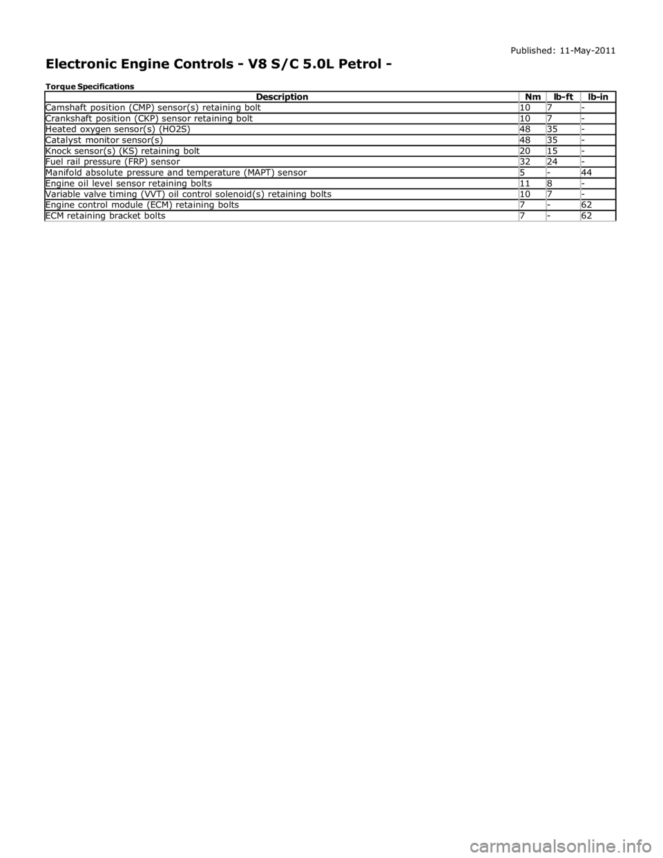
Camshaft position (CMP) sensor(s) retaining bolt 10 7 - Crankshaft position (CKP) sensor retaining bolt 10 7 - Heated oxygen sensor(s) (HO2S) 48 35 - Catalyst monitor sensor(s) 48 35 - Knock sensor(s) (KS) retaining bolt 20 15 - Fuel rail pressure (FRP) sensor 32 24 - Manifold absolute pressure and temperature (MAPT) sensor 5 - 44 Engine oil level sensor retaining bolts 11 8 - Variable valve timing (VVT) oil control solenoid(s) retaining bolts 10 7 - Engine control module (ECM) retaining bolts 7 - 62 ECM retaining bracket bolts 7 - 62
Page 1357 of 3039

Published: 11-May-2011
Electronic Engine Controls - V8 S/C 5.0L Petrol - Electronic Engine Controls - Overview
Description and Operation
OVERVIEW
The EEC (electronic engine control) system operates the engine to generate the output demanded by the accelerator pedal and
loads imposed by other systems. The EEC system has an ECM (engine control module) that uses a torque-based strategy to evaluate inputs from sensors and other systems, then produces outputs to engine actuators to produce the required torque.
The EEC system controls the following: Charge air
Fueling
Ignition timing
Valve timing
Cylinder knock
Noise feedback system
Idle speed
Engine cooling fan
Evaporative emissions
On-board diagnostics
Immobilization system interface
Speed control.
Page 1362 of 3039
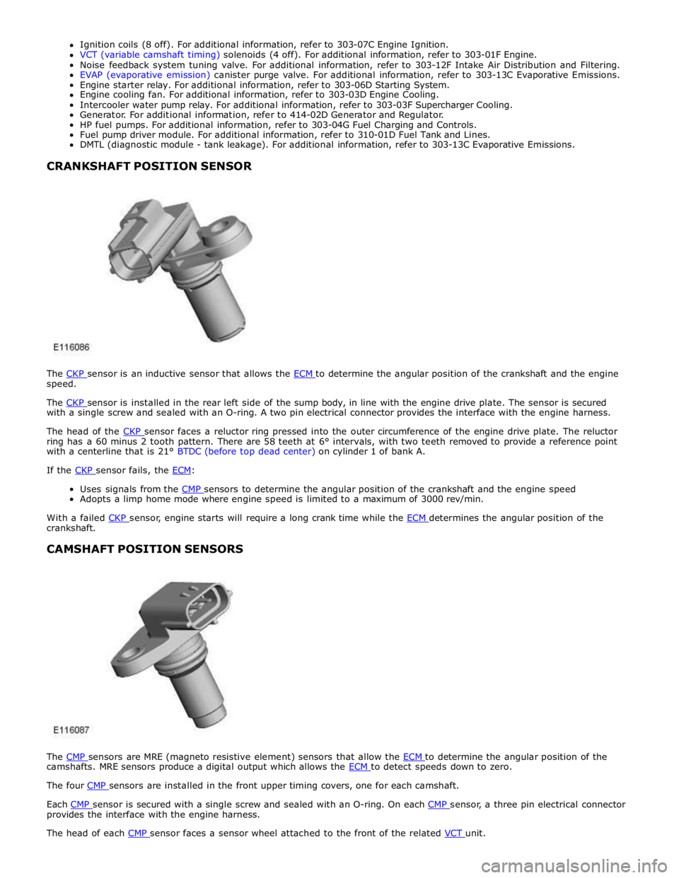
speed.
The CKP sensor is installed in the rear left side of the sump body, in line with the engine drive plate. The sensor is secured with a single screw and sealed with an O-ring. A two pin electrical connector provides the interface with the engine harness.
The head of the CKP sensor faces a reluctor ring pressed into the outer circumference of the engine drive plate. The reluctor ring has a 60 minus 2 tooth pattern. There are 58 teeth at 6° intervals, with two teeth removed to provide a reference point
with a centerline that is 21° BTDC (before top dead center) on cylinder 1 of bank A.
If the CKP sensor fails, the ECM:
Uses signals from the CMP sensors to determine the angular position of the crankshaft and the engine speed Adopts a limp home mode where engine speed is limited to a maximum of 3000 rev/min.
With a failed CKP sensor, engine starts will require a long crank time while the ECM determines the angular position of the crankshaft.
CAMSHAFT POSITION SENSORS
The CMP sensors are MRE (magneto resistive element) sensors that allow the ECM to determine the angular position of the camshafts. MRE sensors produce a digital output which allows the ECM to detect speeds down to zero. The four CMP sensors are installed in the front upper timing covers, one for each camshaft.
Each CMP sensor is secured with a single screw and sealed with an O-ring. On each CMP sensor, a three pin electrical connector provides the interface with the engine harness.
The head of each CMP sensor faces a sensor wheel attached to the front of the related VCT unit.