2010 JAGUAR XFR navigation
[x] Cancel search: navigationPage 2154 of 3039
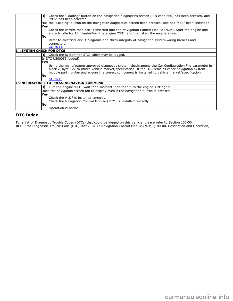
Check the "Loading" button on the navigation diagnostics screen (PIN code 660) has been pressed, and "YES" has been selected. Has the "Loading" button on the navigation diagnostics screen been pressed, and has "YES" been selected? Yes
Check the correct map disc is inserted into the Navigation Control Module (NCM). Start the engine and
allow to idle for 15 minutesTurn the engine 'OFF', and then start the engine again.
No
Refer to electrical circuit diagrams and check integrity of navigation system wiring harness and
connectors.
GO to I4. I4: SYSTEM CHECK FOR DTCS 1 Check the system for DTCs which may be logged. Is DTC U300055 logged? Yes
Using the manufacturer approved diagnostic system check/amend the Car Configuration File parameter in
block 2, byte 127 to match vehicle market/specification. If the DTC remains check navigation system
module part number and ensure the correct component is installed to vehicle market/specification.
No
GO to I5. I5: NO RESPONSE TO PRESSING NAVIGATION MENU 1 Turn the engine 'OFF', wait for a moment, and then turn the engine 'ON' again. Does the navigation screen fail to display even if the navigation button is pressed? Yes
Check the HLDF is installed correctly.
Check the Navigation Control Module (NCM) is installed correctly.
No
Operation is normal. DTC Index
For a list of Diagnostic Trouble Codes (DTCs) that could be logged on this vehicle, please refer to Section 100-00.
REFER to: Diagnostic Trouble Code (DTC) Index - DTC: Navigation Control Module (NCM) (100-00, Description and Operation).
Page 2157 of 3039
(414-01 Battery, Mounting and Cables, General Procedures).
2. Remove the LH luggage compartment side trim panel.
For additional information, refer to: Loadspace Trim Panel LH (501-05 Interior Trim and Ornamentation, Removal and Installation).
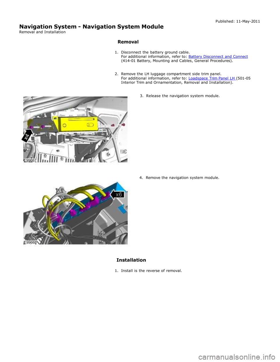
3. Release the navigation system module.
4. Remove the navigation system module.
Installation
1. Install is the reverse of removal.
Page 2172 of 3039
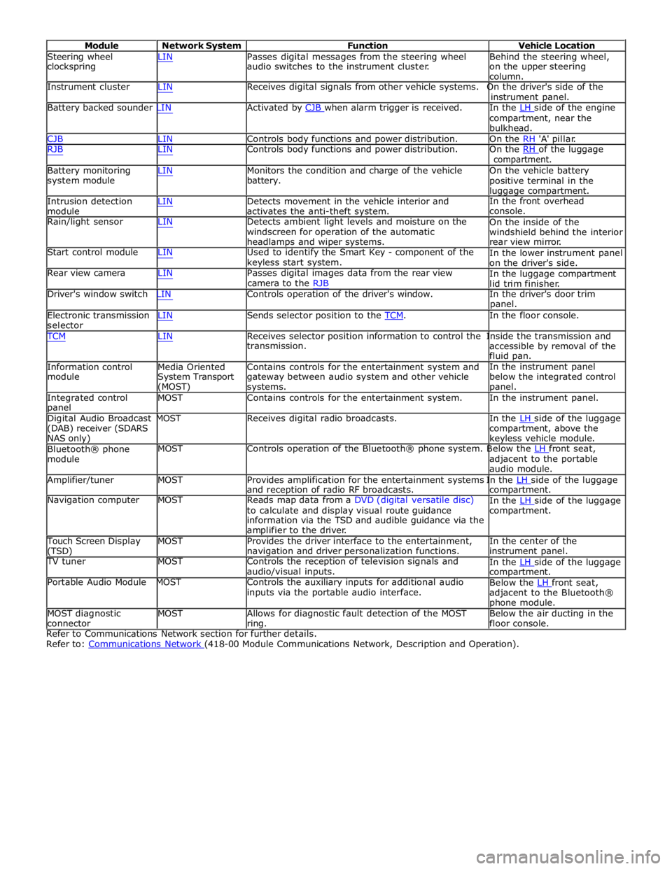
Module Network System Function Vehicle Location
Steering wheel
clockspring LIN Passes digital messages from the steering wheel
audio switches to the instrument cluster. Behind the steering wheel,
on the upper steering
column.
Instrument cluster LIN Receives digital signals from other vehicle systems. On the driver's side of the
instrument panel.
Battery backed sounder LIN Activated by CJB when alarm trigger is received. In the LH side of the engine compartment, near the
bulkhead.
CJB LIN Controls body functions and power distribution. On the RH 'A' pillar.
RJB LIN Controls body functions and power distribution. On the RH of the luggage compartment.
Battery monitoring
system module
Intrusion detection
module LIN Monitors the condition and charge of the vehicle
battery.
LIN Detects movement in the vehicle interior and
activates the anti-theft system. On the vehicle battery
positive terminal in the
luggage compartment.
In the front overhead
console.
Rain/light sensor LIN Detects ambient light levels and moisture on the
windscreen for operation of the automatic
headlamps and wiper systems.
Start control module LIN Used to identify the Smart Key - component of the
keyless start system.
Rear view camera LIN Passes digital images data from the rear view
camera to the RJB On the inside of the
windshield behind the interior
rear view mirror.
In the lower instrument panel
on the driver's side.
In the luggage compartment
lid trim finisher.
Driver's window switch LIN Controls operation of the driver's window. In the driver's door trim
panel.
Electronic transmission
selector LIN Sends selector position to the TCM. In the floor console. TCM LIN Receives selector position information to control the Inside the transmission and
Information control
module
Media Oriented
System Transport
(MOST) transmission.
Contains controls for the entertainment system and
gateway between audio system and other vehicle
systems. accessible by removal of the
fluid pan.
In the instrument panel
below the integrated control
panel.
Integrated control
panel MOST Contains controls for the entertainment system. In the instrument panel.
Digital Audio Broadcast MOST Receives digital radio broadcasts. In the LH side of the luggage (DAB) receiver (SDARS
NAS only)
Bluetooth® phone
module compartment, above the
keyless vehicle module.
MOST Controls operation of the Bluetooth® phone system. Below the LH front seat, adjacent to the portable
audio module.
Amplifier/tuner MOST Provides amplification for the entertainment systems In the LH side of the luggage and reception of radio RF broadcasts.
Navigation computer MOST Reads map data from a DVD (digital versatile disc)
to calculate and display visual route guidance
information via the TSD and audible guidance via the
amplifier to the driver. compartment.
In the LH side of the luggage compartment.
Touch Screen Display
(TSD) MOST Provides the driver interface to the entertainment,
navigation and driver personalization functions. In the center of the
instrument panel.
TV tuner MOST Controls the reception of television signals and
audio/visual inputs.
Portable Audio Module MOST Controls the auxiliary inputs for additional audio
inputs via the portable audio interface. In the LH side of the luggage compartment.
Below the LH front seat, adjacent to the Bluetooth®
phone module.
MOST diagnostic
connector MOST Allows for diagnostic fault detection of the MOST
ring. Below the air ducting in the
floor console.
Refer to Communications Network section for further details.
Refer to: Communications Network (418-00 Module Communications Network, Description and Operation).
Page 2829 of 3039
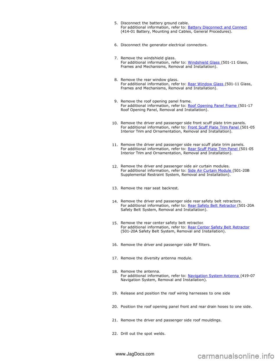
(414-01 Battery, Mounting and Cables, General Procedures).
6. Disconnect the generator electrical connectors.
7. Remove the windshield glass.
For additional information, refer to: Windshield Glass (501-11 Glass, Frames and Mechanisms, Removal and Installation).
8. Remove the rear window glass.
For additional information, refer to: Rear Window Glass (501-11 Glass, Frames and Mechanisms, Removal and Installation).
9. Remove the roof opening panel frame.
For additional information, refer to: Roof Opening Panel Frame (501-17 Roof Opening Panel, Removal and Installation).
10. Remove the driver and passenger side front scuff plate trim panels.
For additional information, refer to: Front Scuff Plate Trim Panel (501-05 Interior Trim and Ornamentation, Removal and Installation).
11. Remove the driver and passenger side rear scuff plate trim panels.
For additional information, refer to: Rear Scuff Plate Trim Panel (501-05 Interior Trim and Ornamentation, Removal and Installation).
12. Remove the driver and passenger side air curtain modules.
For additional information, refer to: Side Air Curtain Module (501-20B Supplemental Restraint System, Removal and Installation).
13. Remove the rear seat backrest.
14. Remove the driver and passenger side rear safety belt retractors.
For additional information, refer to: Rear Safety Belt Retractor (501-20A Safety Belt System, Removal and Installation).
15. Remove the rear center safety belt retractor.
For additional information, refer to: Rear Center Safety Belt Retractor (501-20A Safety Belt System, Removal and Installation).
16. Remove the driver and passenger side RF filters.
17. Remove the diversity antenna module.
18. Remove the antenna.
For additional information, refer to: Navigation System Antenna (419-07 Navigation System, Removal and Installation).
19. Release and position the roof wiring harnesses to one side
20. Position the roof opening panel front and rear drain hoses to one side.
21. Remove the driver and passenger side roof mouldings.
22. Drill out the spot welds.
www.JagDocs.com
Page 2836 of 3039
(414-01 Battery, Mounting and Cables, General Procedures).
6. Disconnect the generator electrical connectors.
7. Remove the windshield glass.
For additional information, refer to: Windshield Glass (501-11 Glass, Frames and Mechanisms, Removal and Installation).
8. Remove the rear window glass.
For additional information, refer to: Rear Window Glass (501-11 Glass, Frames and Mechanisms, Removal and Installation).
9. Remove the headliner.
For additional information, refer to: Headliner (501-05 Interior Trim and Ornamentation, Removal and Installation).
10. Remove the driver and passenger side front scuff plate trim panels.
For additional information, refer to: Front Scuff Plate Trim Panel (501-05 Interior Trim and Ornamentation, Removal and Installation).
11. Remove the driver and passenger side rear scuff plate trim panels.
For additional information, refer to: Rear Scuff Plate Trim Panel (501-05 Interior Trim and Ornamentation, Removal and Installation).
12. Remove the driver and passenger side air curtain modules.
For additional information, refer to: Side Air Curtain Module (501-20B Supplemental Restraint System, Removal and Installation).
13. Remove the rear seat backrest.
14. Remove the driver and passenger side rear safety belt retractors.
For additional information, refer to: Rear Safety Belt Retractor (501-20A Safety Belt System, Removal and Installation).
15. Remove the rear center safety belt retractor.
For additional information, refer to: Rear Center Safety Belt Retractor (501-20A Safety Belt System, Removal and Installation).
16. Remove the driver and passenger side RF filters.
17. Remove the diversity antenna module.
18. Remove the antenna.
For additional information, refer to: Navigation System Antenna (419-07 Navigation System, Removal and Installation).
19. Release and position the roof wiring harnesses to one side
20. Remove the driver and passenger side roof mouldings.
21. Drill out the spot welds.