2010 JAGUAR XFR navigation
[x] Cancel search: navigationPage 1947 of 3039
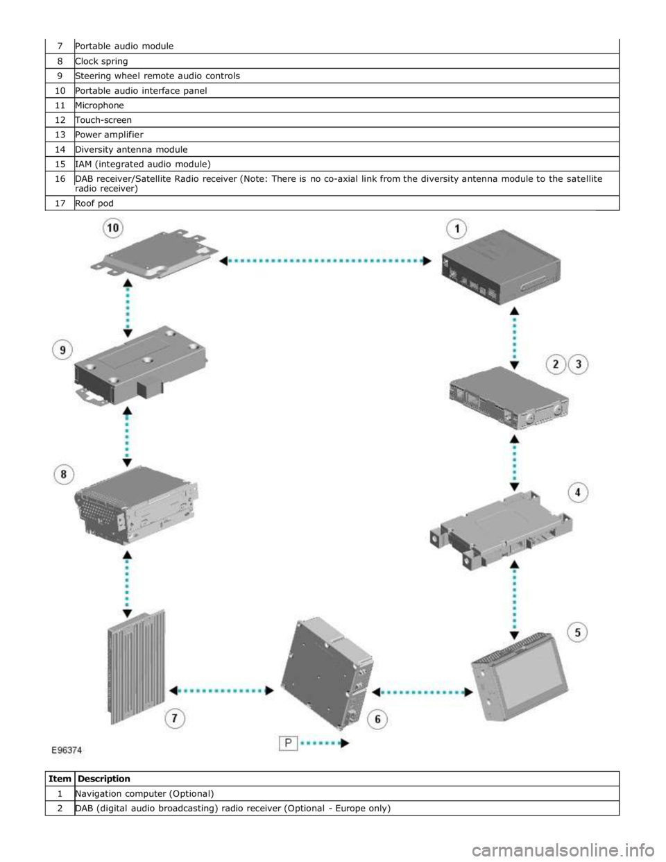
8 Clock spring 9 Steering wheel remote audio controls 10 Portable audio interface panel 11 Microphone 12 Touch-screen 13 Power amplifier 14 Diversity antenna module 15 IAM (integrated audio module) 16 DAB receiver/Satellite Radio receiver (Note: There is no co-axial link from the diversity antenna module to the satellite radio receiver) 17 Roof pod
Item Description 1 Navigation computer (Optional) 2 DAB (digital audio broadcasting) radio receiver (Optional - Europe only)
Page 1948 of 3039
3 Satellite Radio digital receiver (Optional - NAS only) 4 Telephone control module (Optional) 5 Touch-screen 6 TV tuner (Optional) 7 Power amplifier (Not fitted to the Jaguar Sound System) 8 IAM (integrated audio module) 9 Portable audio module (Optional) 10 ICM (information control module)
AUDIO SYSTEM OPERATION System Operation
The components of the audio/infotainment system are all connected on the MOST (media orientated systems transport) ring.
The MOST (media orientated systems transport) ring is a fibre optic communications bus for multimedia applications. Audio
and control information is passed around the MOST (media orientated systems transport) ring and can be picked up by any of
the systems units. For example, radio station tuning/selection input by the vehicle user into the Touch-screen is sent along the
MOST (media orientated systems transport) ring and collected by the IAM (integrated audio module) which then selects the
requested radio station.
MOST (media orientated systems transport) technology uses a plastic optical fibre which forms a network connecting the audio
and multimedia system components. Each component in the ring is connected to the plastic optical fibre through a device
known as a FOT (fibre optical transceiver). Each FOT (fibre optical transceiver) has two optical connections; one connection is
sensitive to light and is the input, the second connection forms the light source and is the output. The system operates by
connecting the output from one FOT (fibre optical transceiver) to the input of another FOT (fibre optical transceiver).
The light signals are sent in one direction only and are formed in the following way:
Electrical signals are converted into an electrical current
The current then drives an LED (light emitting diode) in the FOT (fibre optical transceiver) to produce a high intensity
red light
The LED transmits the light through a fibre optic cable A photo diode in the FOT (fibre optical transceiver) at the opposite end of the fibre optic cable detects the light.
The following components may be connected to the MOST ring dependant on the vehicle equipment level:
IAM (integrated audio module)
Touch-screen
ICM (information control module)
DAB (digital audio broadcasting) radio receiver (Optional - Europe only)
Satellite radio digital receiver (Optional - NAS only)
Power amplifier (Not fitted to the Jaguar Sound System)
Portable audio module (Optional)
Telephone control module (Optional)
Navigation computer (Optional)
TV tuner (Optional)
NOTE: Do not view the red light directly
MOST is a synchronous network. A timing master supplies the clock information and all other devices on the network
synchronize their operation to this clock. The timing master for the MOST (media orientated systems transport) network on this
vehicle is the ICM (information control module). This unit also controls and manages the MOST (media orientated systems
transport) ring and the system components.
An Optical Bus tester is used in conjunction with the Jaguar diagnostic system to diagnose the MOST (media orientated
systems transport) system. The Optical Bus tester emits a visible, high intensity red light which can be connected into the ring
at any point to test the ring integrity. Disconnecting a MOST (media orientated systems transport) connector will reveal if the
high intensity red light is visible.
If a break occurs in the MOST (media orientated systems transport) ring fault codes are stored in the ICM (information control
module) which can be retrieved using the Jaguar diagnostic system equipment.
With reference to the audio system information and signal transfer the instrument cluster is the gateway between the high
and medium speed CAN bus communication protocols. The ICM (information control module) is the gateway between medium speed CAN and the MOST (media orientated systems transport) systems.
A typical example of information transfer is vehicle speed information from the ABS (anti-lock brake system) module used to
control the automatic volume control function. The vehicle speed information from the ABS module is sent on the high speed CAN network and collected by the instrument panel gateway. The signal is passed to the medium speed CAN network and onto the ICM (information control module) gateway. The ICM (information control module) calculates the volume adjustment
required. The corrected audio volume level signal is sent on the MOST (media orientated systems transport) network to the
IAM (integrated audio module) or Power amplifier (dependant on vehicle equipment level) for output to the speaker system.
Page 1949 of 3039
systems.
A typical example of information transfer is vehicle speed information from the ABS (anti-lock brake system) module used to
control the automatic volume control function. The vehicle speed information from the ABS module is sent on the high speed
CAN network and collected by the instrument panel gateway. The signal is passed to the medium speed CAN network and onto the ICM gateway. The ICM calculates the volume adjustment required. The corrected audio volume level signal is sent on the
MOST network to the IAM or Power amplifier (dependant on vehicle equipment level) for output to the speaker system.
AUDIO SYSTEM USER CONTROLS
Touch-Screen
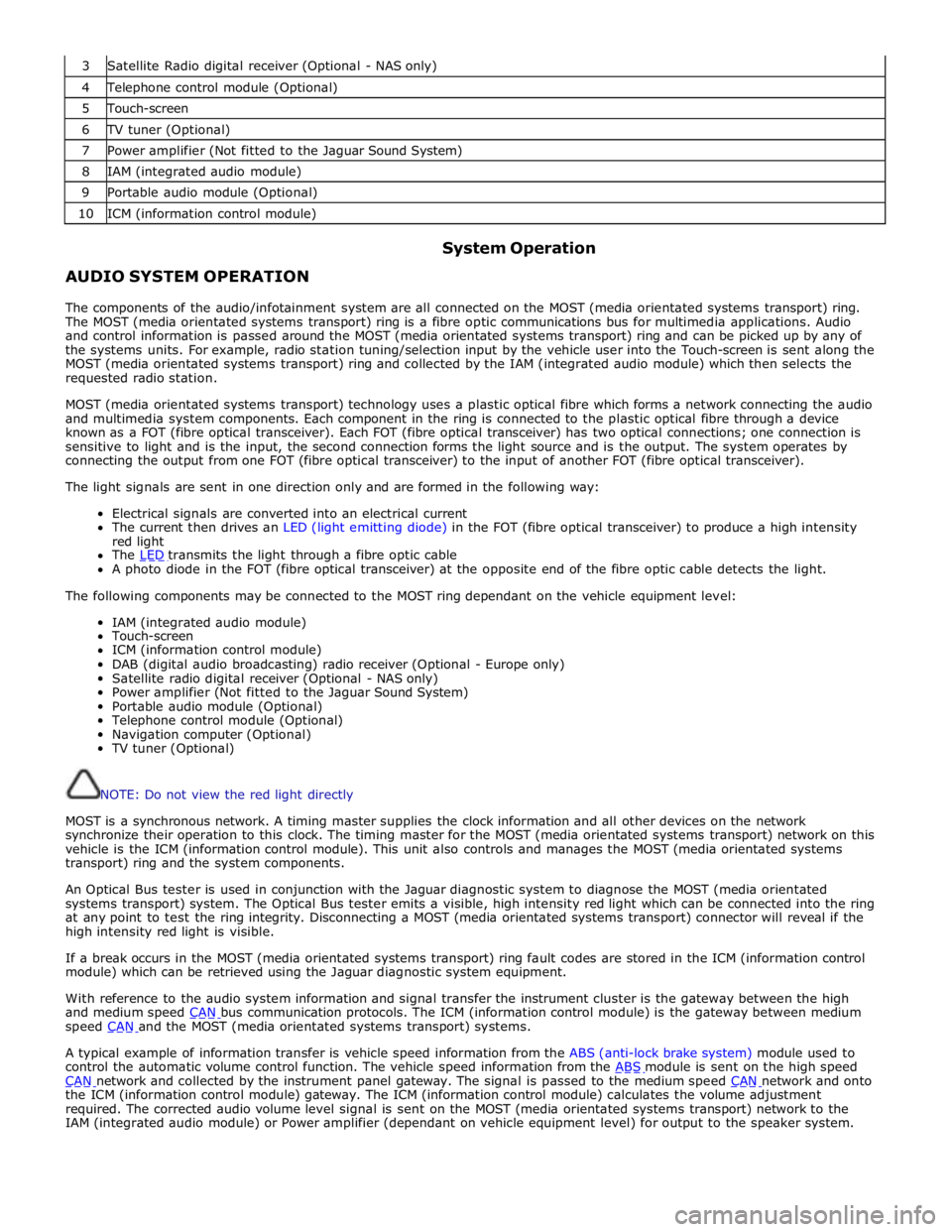
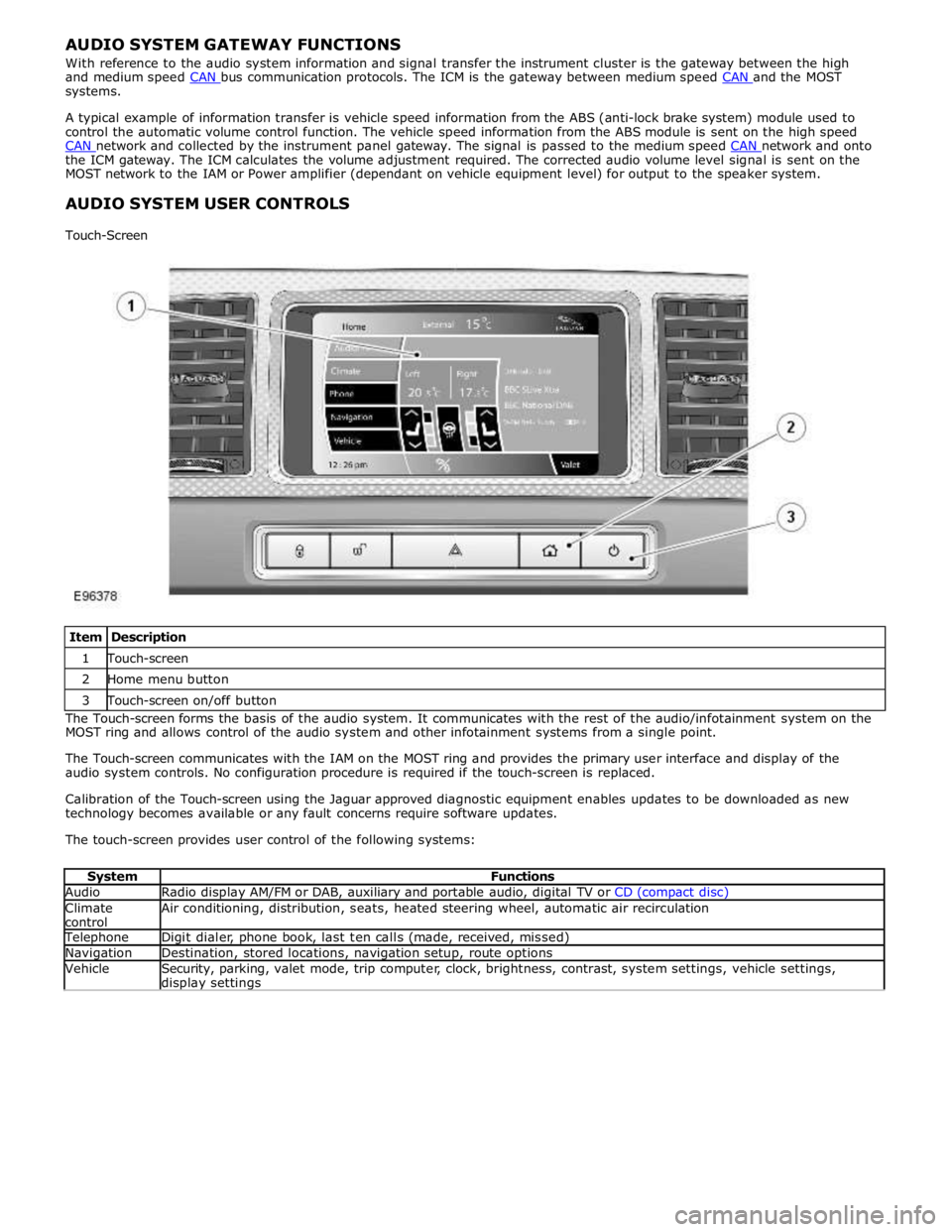
Item Description 1 Touch-screen 2 Home menu button 3 Touch-screen on/off button The Touch-screen forms the basis of the audio system. It communicates with the rest of the audio/infotainment system on the
MOST ring and allows control of the audio system and other infotainment systems from a single point.
The Touch-screen communicates with the IAM on the MOST ring and provides the primary user interface and display of the
audio system controls. No configuration procedure is required if the touch-screen is replaced.
Calibration of the Touch-screen using the Jaguar approved diagnostic equipment enables updates to be downloaded as new
technology becomes available or any fault concerns require software updates.
The touch-screen provides user control of the following systems:
System Functions Audio Radio display AM/FM or DAB, auxiliary and portable audio, digital TV or CD (compact disc) Climate
control Air conditioning, distribution, seats, heated steering wheel, automatic air recirculation Telephone Digit dialer, phone book, last ten calls (made, received, missed) Navigation Destination, stored locations, navigation setup, route options Vehicle
Security, parking, valet mode, trip computer, clock, brightness, contrast, system settings, vehicle settings, display settings
Page 1950 of 3039
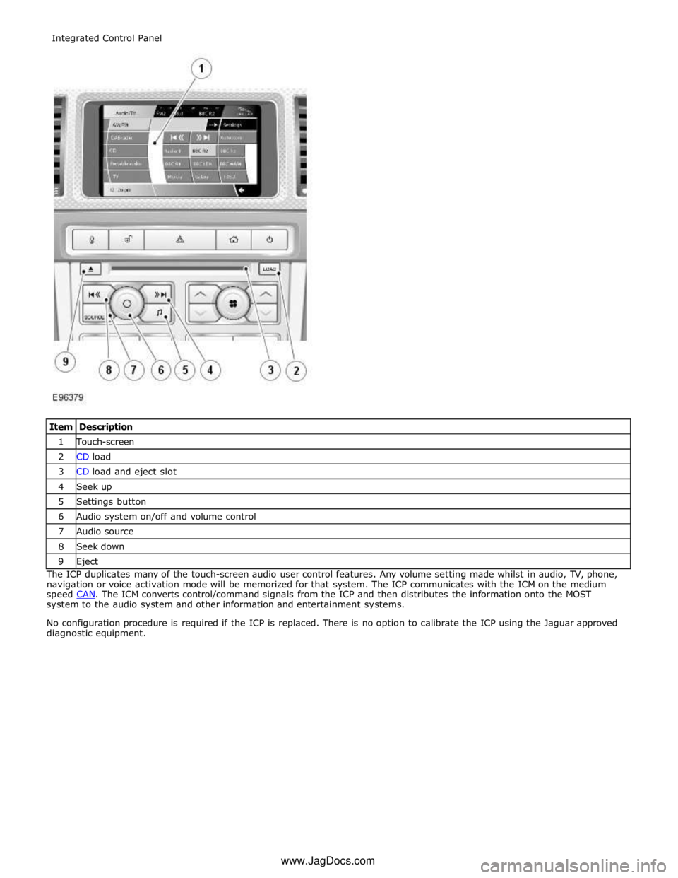
1 Touch-screen 2 CD load 3 CD load and eject slot 4 Seek up 5 Settings button 6 Audio system on/off and volume control 7 Audio source 8 Seek down 9 Eject The ICP duplicates many of the touch-screen audio user control features. Any volume setting made whilst in audio, TV, phone,
navigation or voice activation mode will be memorized for that system. The ICP communicates with the ICM on the medium
speed CAN. The ICM converts control/command signals from the ICP and then distributes the information onto the MOST system to the audio system and other information and entertainment systems.
No configuration procedure is required if the ICP is replaced. There is no option to calibrate the ICP using the Jaguar approved
diagnostic equipment. Integrated Control Panel
www.JagDocs.com
Page 1953 of 3039
7 Triple TV antenna module 8 RF filter The diversity antenna module, located on the left hand side of the heated rear window, receives signals from four antennas
located in the heated rear window, where one antenna is dedicated as an AM antenna.
The diversity tuning system ensures that the strongest signals are used by the radio system to ensure the best possible FM
reception. Using the three remaining receiving antennas serves to eliminate multipath signal distortion. Typically, the signal
from the antenna with the least noise is chosen, and the other antennas are ignored.
The diversity antenna module is an interface between the antenna aerials in the heated rear window and audio system
modules/tuners. It provides antenna signals to the AM/FM tuner in the IAM, to the DAB receiver and to the VICS (vehicle
information and communication systems) or TMC (traffic message channel) in the navigation computer.
There are three different types of diversity antenna module fitted depending on the vehicle market and infotainment
equipment specification:
AM/FM with one co-axial output
AM/FM and VICS/TMC with two co-axial outputs
AM/FM, VICS/TMC and DAB band III with three co-axial outputs
The diversity antenna module receives a power supply from the IAM.
Vehicle or other component generated electromagnetic interference may cause unwanted disturbances in the radio and TV
reception signals. The disturbance may interrupt, obstruct, or otherwise degrade or limit the effective performance of the
circuit. It frequently affects the reception of AM radio in urban areas and can also affect FM radio and television reception,
although to a lesser extent.
The RF filters, which act as RF isolators, are located on both sides of the heated rear window and are used to reduce the
electromagnetic interference. The left hand side RF filter is connected across the heated rear window power supply and used to
separate the DC (direct current) interference from the RF signals. The right hand side RF filter is used in conjunction with the
TV antenna module (if fitted). If the TV system is not fitted the filter is linked directly to ground.
INFORMATION CONTROL MODULE
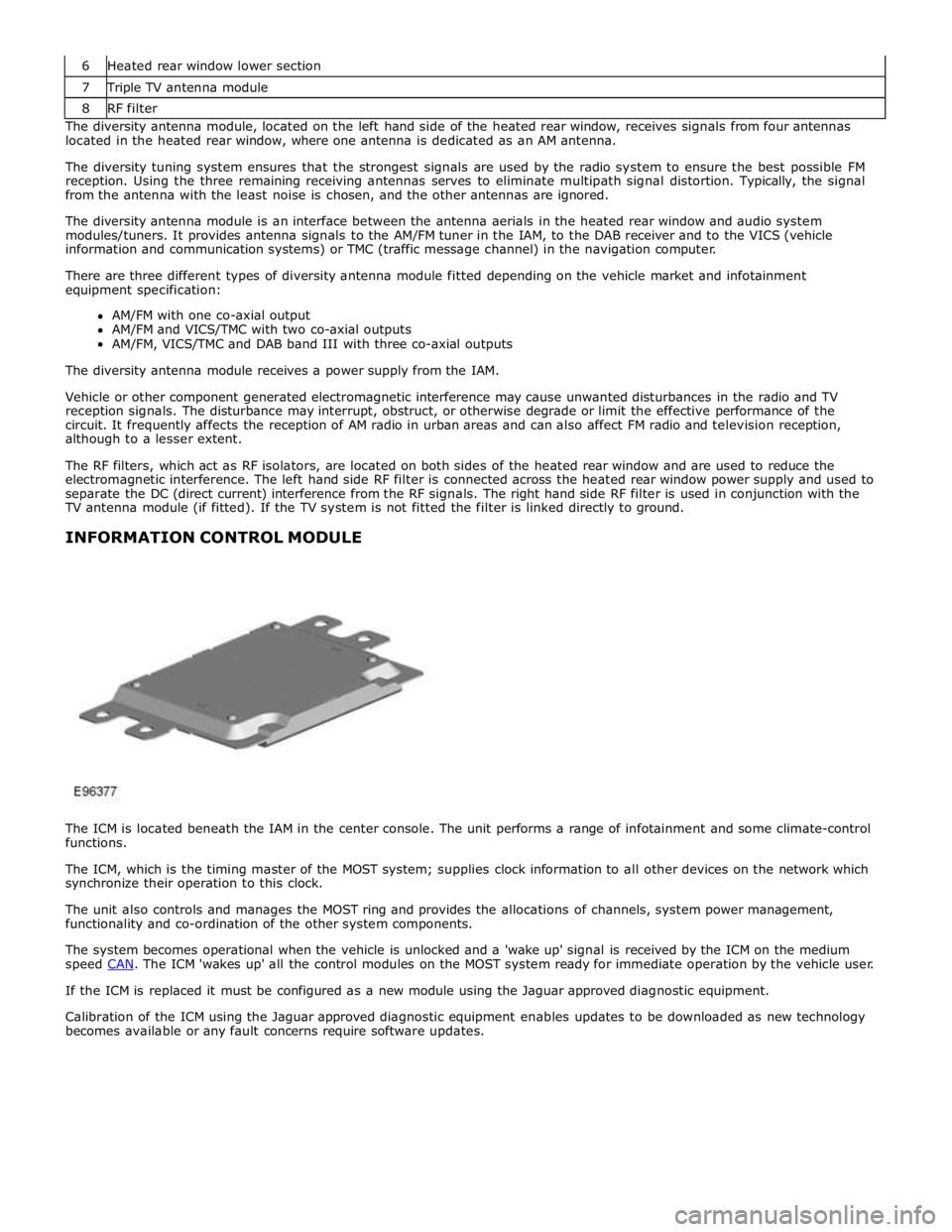
The ICM is located beneath the IAM in the center console. The unit performs a range of infotainment and some climate-control
functions.
The ICM, which is the timing master of the MOST system; supplies clock information to all other devices on the network which
synchronize their operation to this clock.
The unit also controls and manages the MOST ring and provides the allocations of channels, system power management,
functionality and co-ordination of the other system components.
The system becomes operational when the vehicle is unlocked and a 'wake up' signal is received by the ICM on the medium
speed CAN. The ICM 'wakes up' all the control modules on the MOST system ready for immediate operation by the vehicle user. If the ICM is replaced it must be configured as a new module using the Jaguar approved diagnostic equipment.
Calibration of the ICM using the Jaguar approved diagnostic equipment enables updates to be downloaded as new technology
becomes available or any fault concerns require software updates.
Page 1958 of 3039
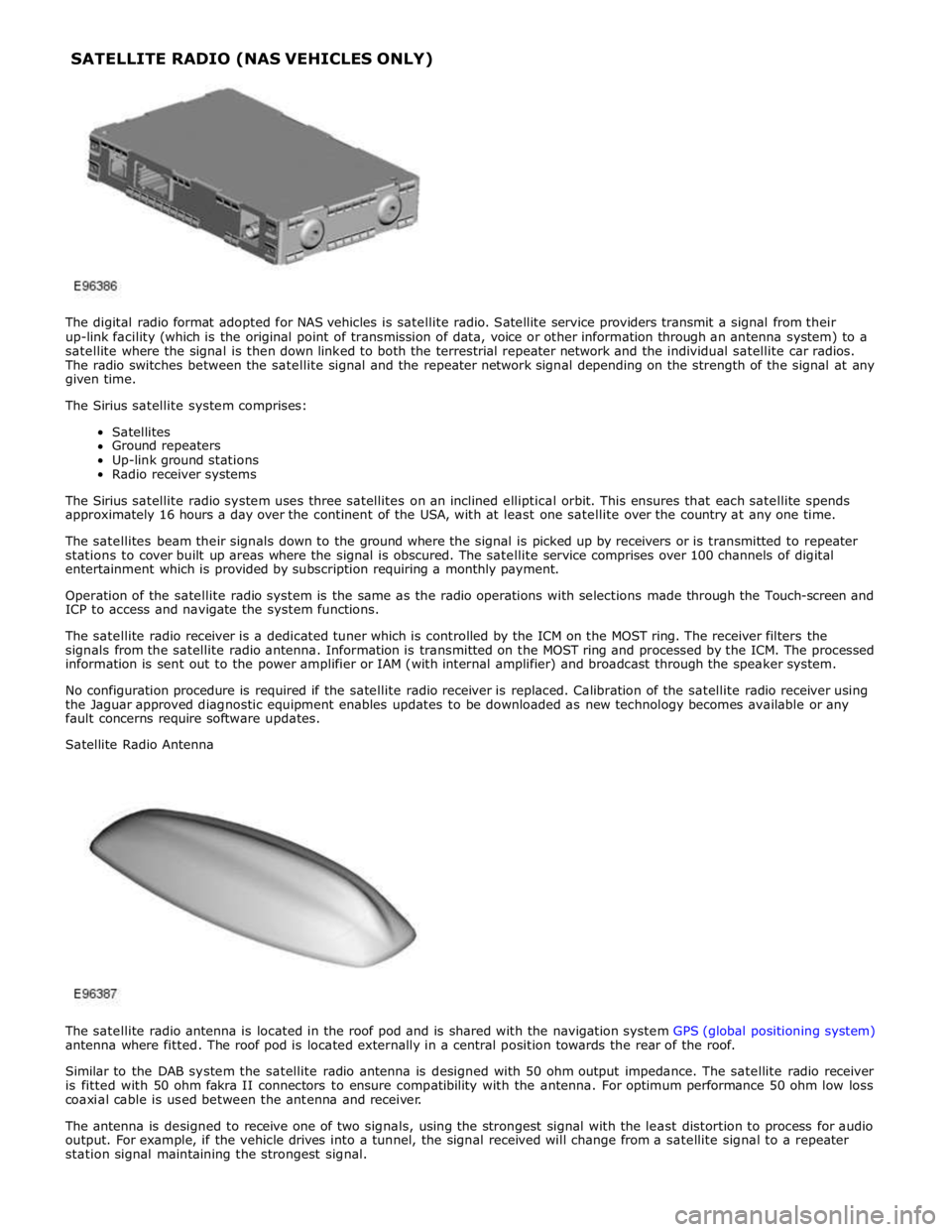
The digital radio format adopted for NAS vehicles is satellite radio. Satellite service providers transmit a signal from their
up-link facility (which is the original point of transmission of data, voice or other information through an antenna system) to a
satellite where the signal is then down linked to both the terrestrial repeater network and the individual satellite car radios.
The radio switches between the satellite signal and the repeater network signal depending on the strength of the signal at any
given time.
The Sirius satellite system comprises:
Satellites
Ground repeaters
Up-link ground stations
Radio receiver systems
The Sirius satellite radio system uses three satellites on an inclined elliptical orbit. This ensures that each satellite spends
approximately 16 hours a day over the continent of the USA, with at least one satellite over the country at any one time.
The satellites beam their signals down to the ground where the signal is picked up by receivers or is transmitted to repeater
stations to cover built up areas where the signal is obscured. The satellite service comprises over 100 channels of digital
entertainment which is provided by subscription requiring a monthly payment.
Operation of the satellite radio system is the same as the radio operations with selections made through the Touch-screen and
ICP to access and navigate the system functions.
The satellite radio receiver is a dedicated tuner which is controlled by the ICM on the MOST ring. The receiver filters the
signals from the satellite radio antenna. Information is transmitted on the MOST ring and processed by the ICM. The processed
information is sent out to the power amplifier or IAM (with internal amplifier) and broadcast through the speaker system.
No configuration procedure is required if the satellite radio receiver is replaced. Calibration of the satellite radio receiver using
the Jaguar approved diagnostic equipment enables updates to be downloaded as new technology becomes available or any
fault concerns require software updates.
Satellite Radio Antenna
The satellite radio antenna is located in the roof pod and is shared with the navigation system GPS (global positioning system)
antenna where fitted. The roof pod is located externally in a central position towards the rear of the roof.
Similar to the DAB system the satellite radio antenna is designed with 50 ohm output impedance. The satellite radio receiver
is fitted with 50 ohm fakra II connectors to ensure compatibility with the antenna. For optimum performance 50 ohm low loss
coaxial cable is used between the antenna and receiver.
The antenna is designed to receive one of two signals, using the strongest signal with the least distortion to process for audio
output. For example, if the vehicle drives into a tunnel, the signal received will change from a satellite signal to a repeater
station signal maintaining the strongest signal. SATELLITE RADIO (NAS VEHICLES ONLY)
Page 1971 of 3039
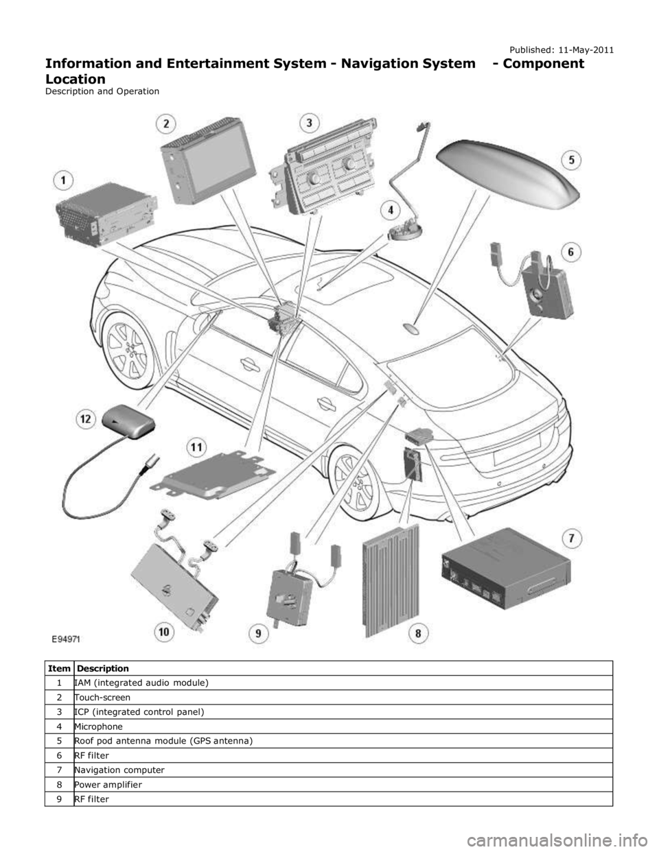
1 IAM (integrated audio module) 2 Touch-screen 3 ICP (integrated control panel) 4 Microphone 5 Roof pod antenna module (GPS antenna) 6 RF filter 7 Navigation computer 8 Power amplifier 9 RF filter
Page 1973 of 3039

Published: 11-May-2011
Information and Entertainment System - Navigation System - Overview
Description and Operation
OVERVIEW
The navigation system provides audible and visual route guidance information to enable the driver to reach a desired
destination. The system allows the driver to choose the desired route using minor or major roads and will present 3 routes to
the driver based on user preferences. Directions to hospitals, museums, monuments and hotels are also available. The
navigation computer uses map information stored on a DVD (digital versatile disc) to determine the best route for the journey
and provide the driver with details of directions and approaching junctions.
The navigation system has various levels of user control through the Touch-screen and JaguarVoice system. System volume
adjustment can be made using the ICP (integrated control panel), Touch-screen and steering wheel controls.
There are 3 navigation system variants specific to various markets. On all systems the GPS (global positioning system) signal
is received by the GPS (global positioning system) antenna located in the roof pod antenna module.
The European navigation system includes the TMC (traffic messaging channel) function, which receives traffic information from
an FM antenna integrated into the heated rear window. On a pre-selected route the system will offer re-routing options
depending on traffic conditions.
The Japanese navigation system includes the VICS (vehicle information and communication systems) function. The VICS
(vehicle information and communication systems) supplies information to enable the navigation computer to re-route the
navigation guidance or to inform the vehicle driver of traffic conditions in the vehicles vicinity. Information is provided to the
system through an FM antenna integrated into the heated rear window and a VICS beacon located in the LH upper side of the
instrument panel.
The NAS (North American specification) variant does not include any additional traffic information systems.
The navigation system is primarily controlled from the Touch-screen which is located in the center of the instrument panel.
Control signals from the Touch-screen are sent on the MOST (media oriented systems transport) ring to the navigation
computer. The navigation computer uses a dedicated GVIF (gigabit video interface) bus to transmit video signals to the Touch-
screen.
Depending upon the audio system version fitted the navigation audio output signals are sent on the MOST (media oriented
systems transport) ring to the IAM (integrated audio module) or the power amplifier for speaker output.