2010 JAGUAR XFR heater
[x] Cancel search: heaterPage 1361 of 3039
DIAGNOSTICS
The ECM stores each fault as a DTC (diagnostic trouble code). The DTC and associated environmental and freeze frame data can be read using Jaguar approved diagnostic equipment, which can also read real time data from each sensor, the adaption
values currently being employed and the current fueling, ignition and idle speed settings.
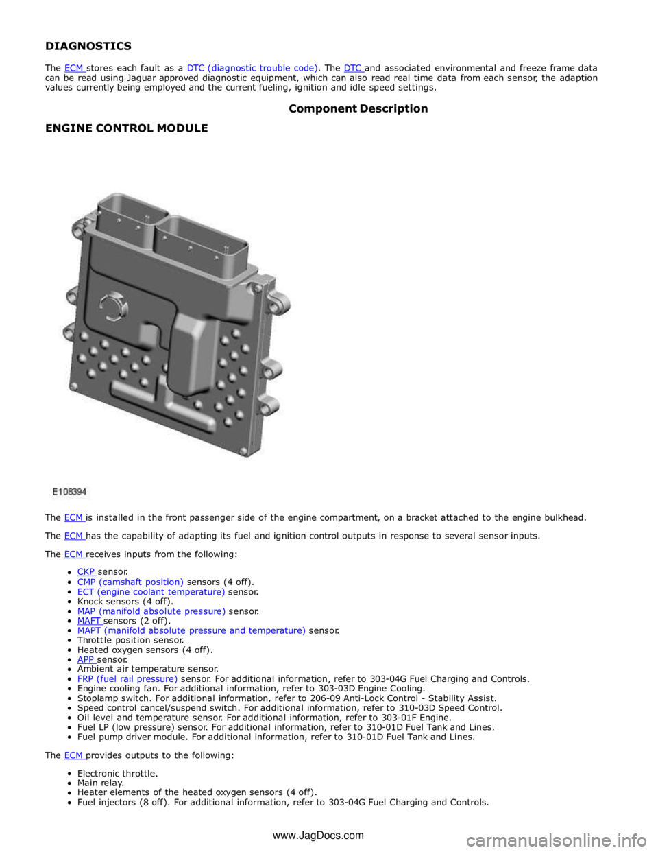
ENGINE CONTROL MODULE Component Description
The ECM is installed in the front passenger side of the engine compartment, on a bracket attached to the engine bulkhead. The ECM has the capability of adapting its fuel and ignition control outputs in response to several sensor inputs. The ECM receives inputs from the following:
CKP sensor. CMP (camshaft position) sensors (4 off).
ECT (engine coolant temperature) sensor.
Knock sensors (4 off).
MAP (manifold absolute pressure) sensor.
MAFT sensors (2 off). MAPT (manifold absolute pressure and temperature) sensor.
Throttle position sensor.
Heated oxygen sensors (4 off).
APP sensor. Ambient air temperature sensor.
FRP (fuel rail pressure) sensor. For additional information, refer to 303-04G Fuel Charging and Controls.
Engine cooling fan. For additional information, refer to 303-03D Engine Cooling.
Stoplamp switch. For additional information, refer to 206-09 Anti-Lock Control - Stability Assist.
Speed control cancel/suspend switch. For additional information, refer to 310-03D Speed Control.
Oil level and temperature sensor. For additional information, refer to 303-01F Engine.
Fuel LP (low pressure) sensor. For additional information, refer to 310-01D Fuel Tank and Lines.
Fuel pump driver module. For additional information, refer to 310-01D Fuel Tank and Lines.
The ECM provides outputs to the following: Electronic throttle.
Main relay.
Heater elements of the heated oxygen sensors (4 off).
Fuel injectors (8 off). For additional information, refer to 303-04G Fuel Charging and Controls. www.JagDocs.com
Page 1363 of 3039
Defaults to base mapping for the ignition timing, with no cylinder correction
Disables the VCT system.
ENGINE COOLANT TEMPERATURE SENSORS
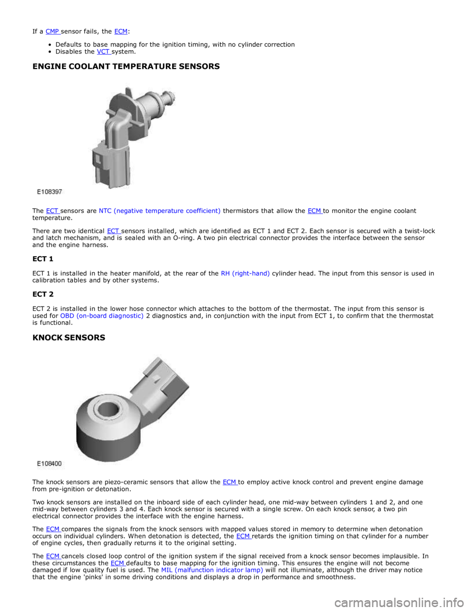
The ECT sensors are NTC (negative temperature coefficient) thermistors that allow the ECM to monitor the engine coolant temperature.
There are two identical ECT sensors installed, which are identified as ECT 1 and ECT 2. Each sensor is secured with a twist-lock and latch mechanism, and is sealed with an O-ring. A two pin electrical connector provides the interface between the sensor
and the engine harness.
ECT 1
ECT 1 is installed in the heater manifold, at the rear of the RH (right-hand) cylinder head. The input from this sensor is used in
calibration tables and by other systems.
ECT 2
ECT 2 is installed in the lower hose connector which attaches to the bottom of the thermostat. The input from this sensor is
used for OBD (on-board diagnostic) 2 diagnostics and, in conjunction with the input from ECT 1, to confirm that the thermostat
is functional.
KNOCK SENSORS
The knock sensors are piezo-ceramic sensors that allow the ECM to employ active knock control and prevent engine damage from pre-ignition or detonation.
Two knock sensors are installed on the inboard side of each cylinder head, one mid-way between cylinders 1 and 2, and one
mid-way between cylinders 3 and 4. Each knock sensor is secured with a single screw. On each knock sensor, a two pin
electrical connector provides the interface with the engine harness.
The ECM compares the signals from the knock sensors with mapped values stored in memory to determine when detonation occurs on individual cylinders. When detonation is detected, the ECM retards the ignition timing on that cylinder for a number of engine cycles, then gradually returns it to the original setting.
The ECM cancels closed loop control of the ignition system if the signal received from a knock sensor becomes implausible. In these circumstances the ECM defaults to base mapping for the ignition timing. This ensures the engine will not become damaged if low quality fuel is used. The MIL (malfunction indicator lamp) will not illuminate, although the driver may notice
that the engine 'pinks' in some driving conditions and displays a drop in performance and smoothness.
Page 1365 of 3039
MANIFOLD ABSOLUTE PRESSURE AND TEMPERATURE SENSOR
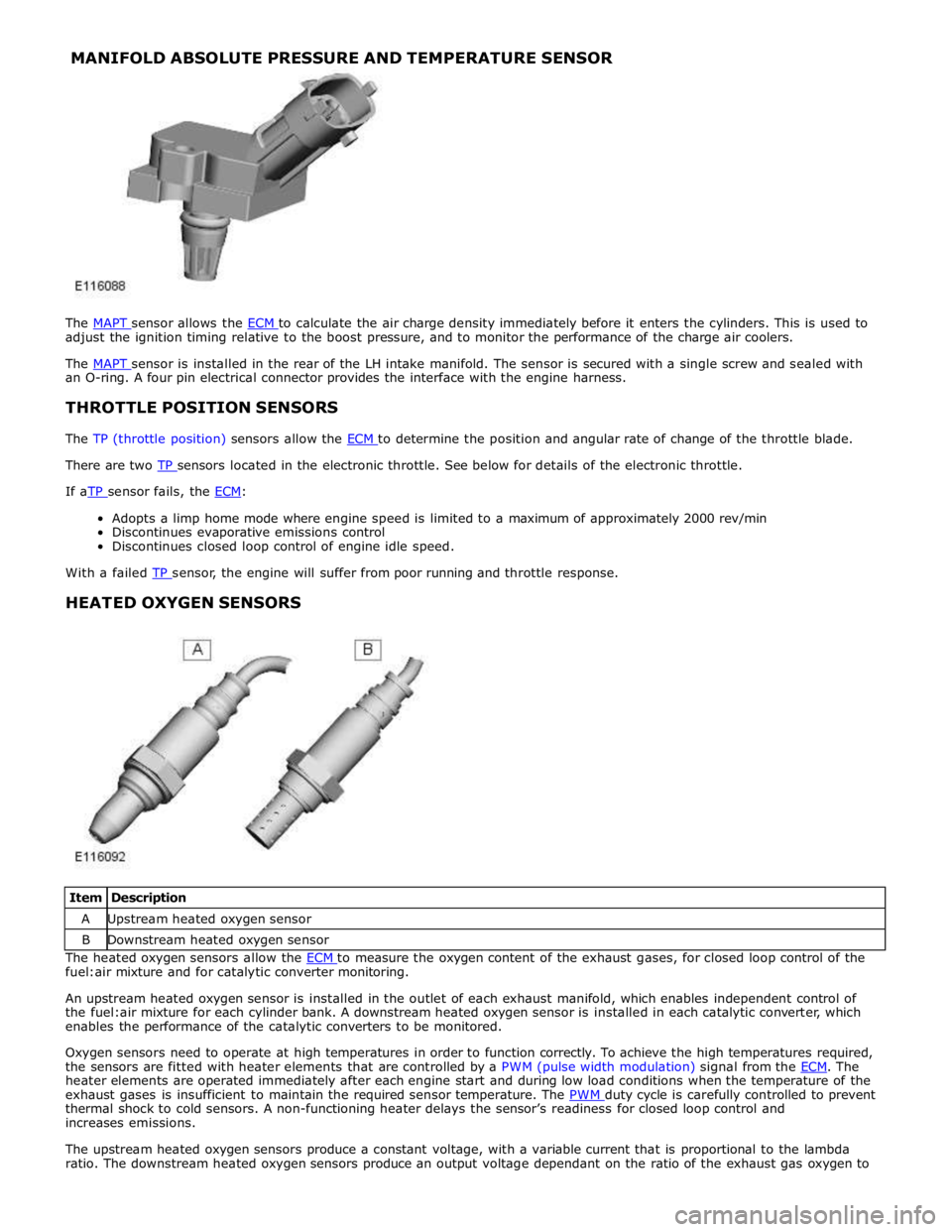
The MAPT sensor allows the ECM to calculate the air charge density immediately before it enters the cylinders. This is used to adjust the ignition timing relative to the boost pressure, and to monitor the performance of the charge air coolers.
The MAPT sensor is installed in the rear of the LH intake manifold. The sensor is secured with a single screw and sealed with an O-ring. A four pin electrical connector provides the interface with the engine harness.
THROTTLE POSITION SENSORS
The TP (throttle position) sensors allow the ECM to determine the position and angular rate of change of the throttle blade. There are two TP sensors located in the electronic throttle. See below for details of the electronic throttle. If aTP sensor fails, the ECM:
Adopts a limp home mode where engine speed is limited to a maximum of approximately 2000 rev/min
Discontinues evaporative emissions control
Discontinues closed loop control of engine idle speed.
With a failed TP sensor, the engine will suffer from poor running and throttle response.
HEATED OXYGEN SENSORS
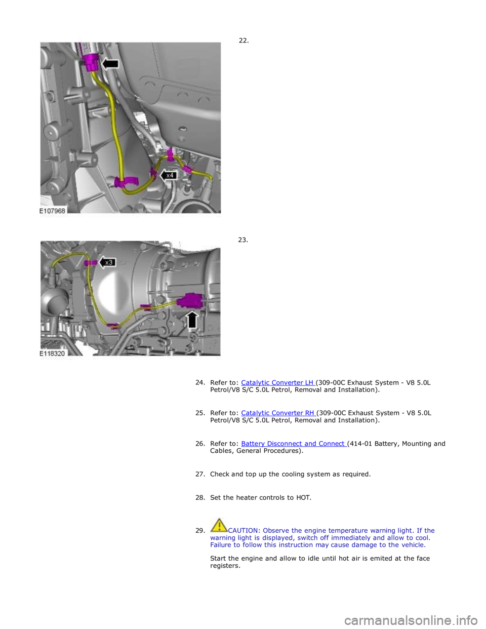
Item Description A Upstream heated oxygen sensor B Downstream heated oxygen sensor The heated oxygen sensors allow the ECM to measure the oxygen content of the exhaust gases, for closed loop control of the fuel:air mixture and for catalytic converter monitoring.
An upstream heated oxygen sensor is installed in the outlet of each exhaust manifold, which enables independent control of
the fuel:air mixture for each cylinder bank. A downstream heated oxygen sensor is installed in each catalytic converter, which
enables the performance of the catalytic converters to be monitored.
Oxygen sensors need to operate at high temperatures in order to function correctly. To achieve the high temperatures required,
the sensors are fitted with heater elements that are controlled by a PWM (pulse width modulation) signal from the ECM. The heater elements are operated immediately after each engine start and during low load conditions when the temperature of the
exhaust gases is insufficient to maintain the required sensor temperature. The PWM duty cycle is carefully controlled to prevent thermal shock to cold sensors. A non-functioning heater delays the sensor’s readiness for closed loop control and
increases emissions.
The upstream heated oxygen sensors produce a constant voltage, with a variable current that is proportional to the lambda
ratio. The downstream heated oxygen sensors produce an output voltage dependant on the ratio of the exhaust gas oxygen to
Page 1486 of 3039
22.
23.
24.
Refer to: Catalytic Converter LH (309-00C Exhaust System - V8 5.0L Petrol/V8 S/C 5.0L Petrol, Removal and Installation).
25. Refer to: Catalytic Converter RH (309-00C Exhaust System - V8 5.0L Petrol/V8 S/C 5.0L Petrol, Removal and Installation).
26. Refer to: Battery Disconnect and Connect (414-01 Battery, Mounting and Cables, General Procedures).
27. Check and top up the cooling system as required.
28. Set the heater controls to HOT.
29. CAUTION: Observe the engine temperature warning light. If the
warning light is displayed, switch off immediately and allow to cool.
Failure to follow this instruction may cause damage to the vehicle.
Start the engine and allow to idle until hot air is emited at the face
registers.
Page 1502 of 3039
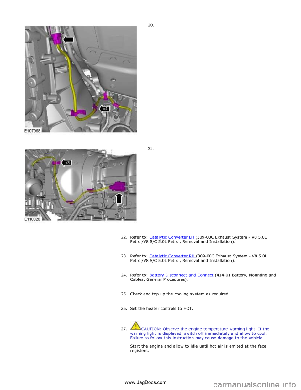
20.
21.
22.
Refer to: Catalytic Converter LH (309-00C Exhaust System - V8 5.0L Petrol/V8 S/C 5.0L Petrol, Removal and Installation).
23. Refer to: Catalytic Converter RH (309-00C Exhaust System - V8 5.0L Petrol/V8 S/C 5.0L Petrol, Removal and Installation).
24. Refer to: Battery Disconnect and Connect (414-01 Battery, Mounting and Cables, General Procedures).
25. Check and top up the cooling system as required.
26. Set the heater controls to HOT.
27. CAUTION: Observe the engine temperature warning light. If the
warning light is displayed, switch off immediately and allow to cool.
Failure to follow this instruction may cause damage to the vehicle.
Start the engine and allow to idle until hot air is emited at the face
registers. www.JagDocs.com
Page 1664 of 3039

Published: 11-Jul-2014
Climate Control System - General Information - Climate Control System
Diagnosis and Testing
Principles of Operation
For a detailed description of the Climate Control System, refer to the relevant Description and Operation sections in the
Workshop Manual. REFER to:
Air Distribution and Filtering (412-01 Climate Control, Description and Operation), Air Distribution and Filtering (412-01 Climate Control, Description and Operation), Air Distribution and Filtering (412-01 Climate Control, Description and Operation), Heating and Ventilation (412-01 Climate Control, Description and Operation), Heating and Ventilation (412-01 Climate Control, Description and Operation), Heating and Ventilation (412-01 Climate Control, Description and Operation), Air Conditioning (412-01 Climate Control, Description and Operation), Air Conditioning (412-01 Climate Control, Description and Operation), Air Conditioning (412-01 Climate Control, Description and Operation), Control Components (412-01 Climate Control, Description and Operation), Control Components (412-01 Climate Control, Description and Operation), Control Components (412-01 Climate Control, Description and Operation), Electric Booster Heater (412-02 Auxiliary Climate Control, Description and Operation), Electric Booster Heater (412-02 Auxiliary Climate Control, Description and Operation), Electric Booster Heater (412-02 Auxiliary Climate Control, Description and Operation).
Inspection and Verification
WARNING: Servicing must be carried out by personnel familiar with both vehicle system and the charging and testing
equipment. All operations must be carried out in a well ventilated area away from open flame and heat sources.
CAUTION: Diagnosis by substitution from a donor vehicle is NOT acceptable. Substitution of control modules does not
guarantee confirmation of a fault, and may also cause additional faults in the vehicle being tested and/or the donor vehicle.
NOTE: Check and rectify basic faults before beginning diagnostic routines involving pinpoint tests.
1. Verify the customer concern
2. Visually inspect for obvious signs of damage and system integrity
Visual Inspection
Mechanical Electrical
Coolant level
Hose(s)
Coolant pump
Control flap(s)
Duct(s)
Vent(s)
Cabin air filter
Drive belt
Air conditioning compressor
Thermostatic expansion valve
Evaporator
Receiver drier
Air conditioning condenser
Refrigerant pipes Auxiliary
drive belt
Fuel fired booster heater
Fuel fired booster heater fuel pump
Fuel fired booster heater fuel pipes
Fuse(s)
Wiring harness
Electrical connectors
Blower
Air conditioning compressor
Electric cooling fan
Automatic Temperature Control Module (ATCM)
Refrigerant pressure sensor
3. If an obvious cause for an observed or reported concern is found, correct the cause (if possible) before proceeding to
the next step
4. If the cause is not visually evident, verify the symptom and refer to the Symptom Chart, alternatively check for
Diagnostic Trouble Codes (DTCs) and refer to the DTC Index
5. Check DDW for open campaigns. Refer to the corresponding bulletins and SSMs which may be valid for the specific
customer complaint and carry out the recommendations as required
Page 1681 of 3039

Published: 15-Nov-2013
Climate Control System - General Information - Air Conditioning (A/C)
Compressor Commissioning
General Procedures
Activation
CAUTION: Failure to follow this instruction may result in damage to the component.
1. Set the ignition to the on position, make sure the air conditioning (A/C)
is in the off position.
2. Start the engine and allow to run for a minimum of 5 minutes.
3. Set the heater controls to 22°C, with the fan speed set to 75%.
4. Switch on the A/C system.
5. Open all air vents in the dashboard.
6. Run the A/C system for a minimum of 5 minutes, while the engine is still
at idle speed.
7. Once this is achieved the compressor is stabilized, with the oil being
distributed evenly throughout the system.
Page 1682 of 3039

Blower motor control module retaining bolts 1 - 9 Foot duct to cross car beam retaining bolt 5 - 44 Climate control assembly to cross car beam retaining bolts 9 - 80 Climate control module retaining bolts 1 - 9 Defrost vent/register blend door actuator retaining bolts 1 - 9 Evaporator pipe bracket retaining bolts 1 - 9 Evaporator housing retaining bolts 1 - 9 Footwell vent/duct blend door actuator retaining bolt 1 - 9 Heater core housing retaining bolts 2 - 18 Sunload sensor retaining bolt 2 - 18 Evaporator core pipes mounting bracket retaining bolts 1 - 9 Evaporator core pipes to thermostatic expansion valve retaining bolt 5 - 44 Thermostatic expansion valve retaining bolts 3 - 26 www.JagDocs.com