2010 JAGUAR XFR heater
[x] Cancel search: heaterPage 1766 of 3039

Published: 11-May-2011
Auxiliary Climate Control - Electric Booster Heater - System Operation and
Component Description
Description and Operation
Control Diagram
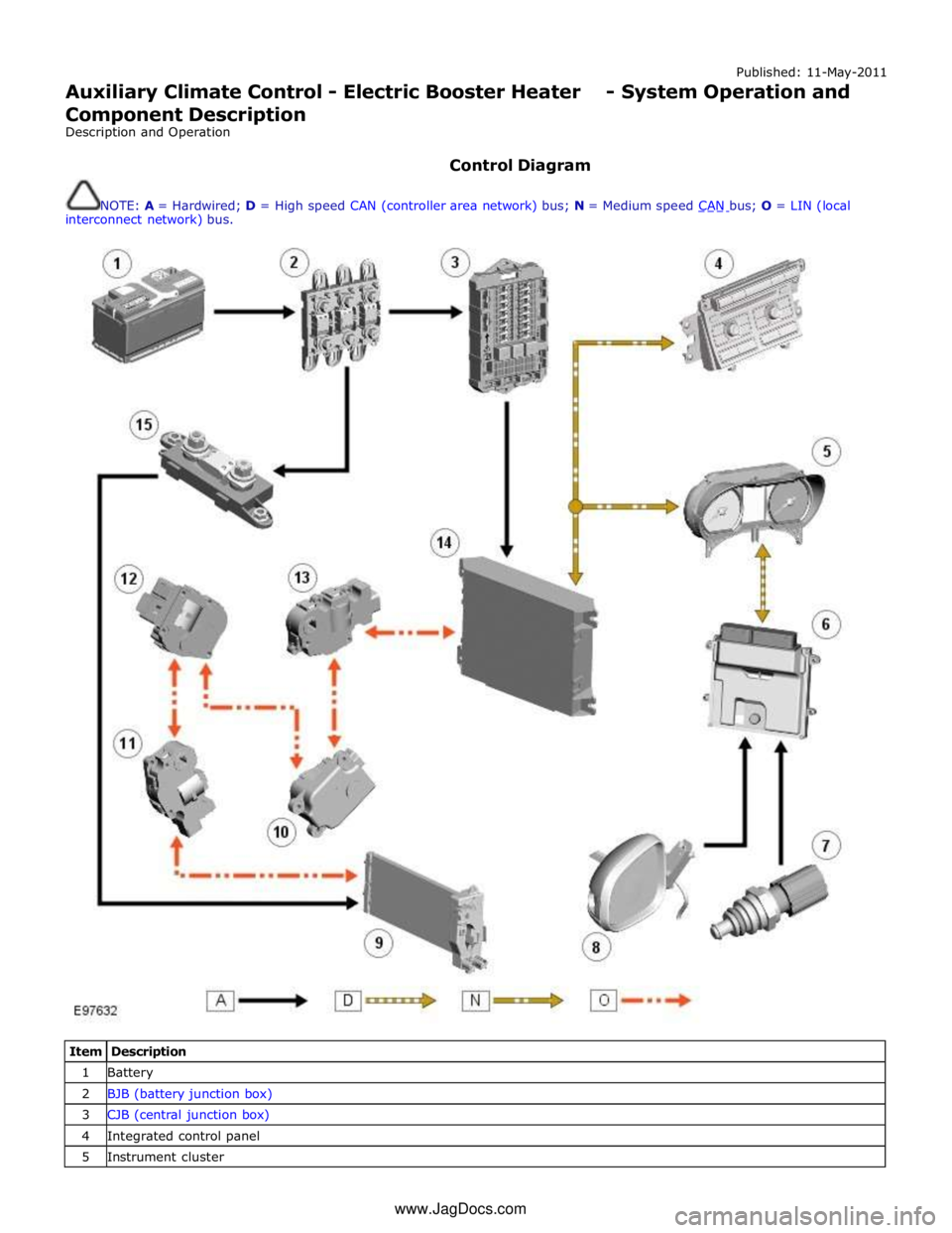
NOTE: A = Hardwired; D = High speed CAN (controller area network) bus; N = Medium speed CAN bus; O = LIN (local interconnect network) bus.
Item Description 1 Battery 2 BJB (battery junction box) 3 CJB (central junction box) 4 Integrated control panel 5 Instrument cluster www.JagDocs.com
Page 1767 of 3039

7 ECT (engine coolant temperature) sensor 8 Ambient temperature sensor 9 Electric booster heater 10 Face/Feet distribution stepper motor 11 RH (right-hand) temperature blend stepper motor 12 LH (left-hand) temperature blend stepper motor 13 Windshield (defrost) distribution stepper motor 14 ATC (automatic temperature control) module 15 150 A megafuse
General System Operation
Operation of the electric booster heater is controlled by the ATC module, which communicates with the micro-controller in the booster heater using the LIN bus. The temperature requested by the ATC module is based on:
The ambient air temperature.
The engine coolant temperature.
The temperatures selected on the integrated control panel.
The blower must be running for the electric booster heater to operate.
If electrical load management is in force, electric booster heater performance is reduced. For additional information, refer to:
Electronic Engine Controls (303-14A, Description and Operation),
Electronic Engine Controls (303-14B Electronic Engine Controls - V6 3.0L Petrol, Description and Operation), Electronic Engine Controls (303-14C, Description and Operation).
Electric Booster Heater Component Description
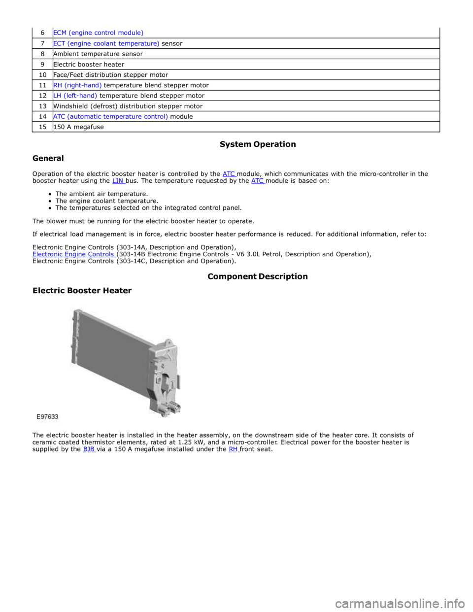
The electric booster heater is installed in the heater assembly, on the downstream side of the heater core. It consists of
ceramic coated thermistor elements, rated at 1.25 kW, and a micro-controller. Electrical power for the booster heater is
supplied by the BJB via a 150 A megafuse installed under the RH front seat.
Page 1772 of 3039

Auxiliary Climate Control - Electric Booster Heater
Removal and Installation
Removal
NOTES:
Removal steps in this procedure may contain installation details.
Some variation in the illustrations may occur, but the essential information is always correct.
All vehicles Published: 11-May-2011
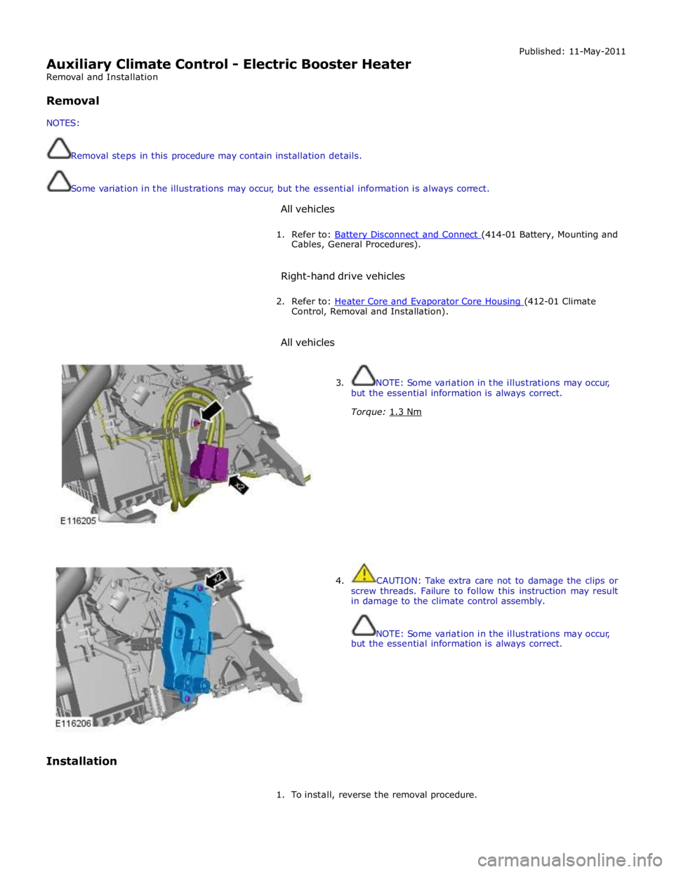
1. Refer to: Battery Disconnect and Connect (414-01 Battery, Mounting and Cables, General Procedures).
Right-hand drive vehicles
2. Refer to: Heater Core and Evaporator Core Housing (412-01 Climate Control, Removal and Installation).
All vehicles
Installation
3. NOTE: Some variation in the illustrations may occur,
but the essential information is always correct.
Torque: 1.3 Nm
4. CAUTION: Take extra care not to damage the clips or
screw threads. Failure to follow this instruction may result
in damage to the climate control assembly.
NOTE: Some variation in the illustrations may occur,
but the essential information is always correct.
1. To install, reverse the removal procedure.
Page 2070 of 3039

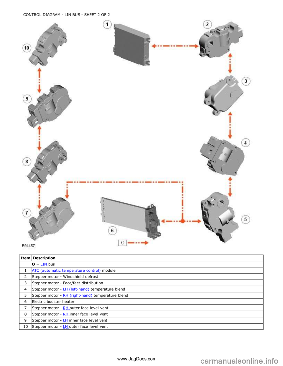
O = LIN bus 1 ATC (automatic temperature control) module 2 Stepper motor - Windshield defrost 3 Stepper motor - Face/feet distribution 4 Stepper motor - LH (left-hand) temperature blend 5 Stepper motor - RH (right-hand) temperature blend 6 Electric booster heater 7 Stepper motor - RH outer face level vent 8 Stepper motor - RH inner face level vent 9 Stepper motor - LH inner face level vent 10 Stepper motor - LH outer face level vent CONTROL DIAGRAM - LIN BUS - SHEET 2 OF 2
www.JagDocs.com
Page 2088 of 3039

DTC Description Possible Cause Action B110011
O2 sensor heater
relay
FPDB O2 sensor heater relay
control circuit - short to ground Carry out any pinpoint tests associated with this DTC
using the manufacturer approved diagnostic system.
Refer to the electrical circuit diagrams and check FPDB O2
sensor heater relay control circuit for short to ground B113D12
Sunroof Global
Open/Close Control
Roof opening panel global
open/close control circuit -
short to power Carry out any pinpoint tests associated with this DTC
using the manufacturer approved diagnostic system.
Refer to the electrical circuit diagrams and check roof
opening panel global open/close control circuit for short
to power B113D14
Sunroof Global
Open/Close Control
Roof opening panel global
open/close control circuit -
short to ground, open circuit Refer to the electrical circuit diagrams and check roof
opening panel global open/close control circuit for short
to ground, open circuit B114011
Engine Crank
Authorisation
Engine crank authorisation
signal circuit - short to ground Carry out any pinpoint tests associated with this DTC
using the manufacturer approved diagnostic system.
Refer to the electrical circuit diagrams and check engine
crank authorisation signal circuit for short to ground B114211 Ignition Status 1
Ignition supply 1 circuits -
short to ground Carry out any pinpoint tests associated with this DTC
using the manufacturer approved diagnostic system.
Refer to the electrical circuit diagrams and check all ignition supply 1 circuits for short to ground B114311 Ignition Status 2
Ignition supply 2 circuits -
short to ground Carry out any pinpoint tests associated with this DTC
using the manufacturer approved diagnostic system.
Refer to the electrical circuit diagrams and check all ignition supply 2 circuits for short to ground B114411
Heated Steering
Wheel Supply
Heated steering wheel supply
circuit - short to ground Carry out any pinpoint tests associated with this DTC
using the manufacturer approved diagnostic system.
Refer to the electrical circuit diagrams and check heated steering wheel supply circuit for short to ground B114511
Glovebox Locking
Motor
Glovebox latch locking motor
circuit - short to ground Carry out any pinpoint tests associated with this DTC
using the manufacturer approved diagnostic system.
Refer to the electrical circuit diagrams and check glovebox latch locking motor circuit for short to ground B114512
Glovebox Locking
Motor
Glovebox latch locking motor
control circuit - short to power Refer to the electrical circuit diagrams and check
glovebox latch locking motor control circuit for short to
power B114513
Glovebox Locking
Motor
Glovebox latch locking motor
control circuit - open circuit Refer to the electrical circuit diagrams and check
glovebox latch locking motor control circuit for open
circuit B114612
Passive sounder
Supply
Security passive sounder
control circuit - short to power Refer to the electrical circuit diagrams and check security
passive sounder control circuit for short to power B114614
Passive sounder
Supply
Security passive sounder
control circuit - short to ground,
open circuit Refer to the electrical circuit diagrams and check security
passive sounder control circuit for short to ground, open
circuit B115811
Front Passenger
Seat Heater Sensor
Front passenger seat heater
sensor circuit - short to ground Carry out any pinpoint tests associated with this DTC
using the manufacturer approved diagnostic system.
Refer to the electrical circuit diagrams and check front passenger seat heater sensor circuit for short to ground B115813
Front Passenger
Seat Heater Sensor
Front passenger seat heater
sensor circuit - open circuit Carry out any pinpoint tests associated with this DTC
using the manufacturer approved diagnostic system.
Refer to the electrical circuit diagrams and check front passenger seat heater sensor circuit for open circuit B115911
Driver Seat Heater
Sensor
Driver seat heater sensor
circuit - short to ground Carry out any pinpoint tests associated with this DTC
using the manufacturer approved diagnostic system.
Refer to the electrical circuit diagrams and check driver
seat heater sensor circuit for short to ground B115913
Driver Seat Heater
Sensor
Driver seat heater sensor
circuit - open circuit Carry out any pinpoint tests associated with this DTC
using the manufacturer approved diagnostic system.
Refer to the electrical circuit diagrams and check driver
seat heater sensor circuit for open circuit B115A11
Front Passenger
Seat Heater
Front passenger seat heater
supply circuit - short to ground Carry out any pinpoint tests associated with this DTC
using the manufacturer approved diagnostic system.
Refer to the electrical circuit diagrams and check front passenger seat heater supply circuit for short to ground B115A15
Front Passenger
Seat Heater
Front passenger seat heater
supply circuit - short to power,
open circuit Carry out any pinpoint tests associated with this DTC
using the manufacturer approved diagnostic system.
Refer to the electrical circuit diagrams and check front
passenger seat heater supply circuit for short to power, open circuit
Page 2089 of 3039

DTC Description Possible Cause Action B115B11 Driver Seat Heater
Driver seat heater supply circuit
- short to ground Carry out any pinpoint tests associated with this DTC
using the manufacturer approved diagnostic system.
Refer to the electrical circuit diagrams and check driver
seat heater supply circuit for short to ground B115B15 Driver Seat Heater
Driver seat heater supply circuit
- short to power, open circuit Carry out any pinpoint tests associated with this DTC
using the manufacturer approved diagnostic system.
Refer to the electrical circuit diagrams and check driver
seat heater supply circuit for short to power, open circuit B117513
Driver Door Ajar
Switch
Driver door ajar switch signal
circuit - open circuit Refer to the electrical circuit diagrams and check driver
door ajar switch signal circuit for open circuit B117613
Passenger Door
Ajar Switch
Passenger door ajar switch
signal circuit - open circuit Refer to the electrical circuit diagrams and check
passenger door ajar switch signal circuit for open circuit B117712
Screenwash Level
Switch
Screenwash level switch signal
circuit - short to power Refer to the electrical circuit diagrams and check
screenwash level switch signal circuit for short to power B11C013
Driver Side Rear
Door Ajar Switch
Left rear door ajar switch signal
circuit - open circuit Refer to the electrical circuit diagrams and check left rear
door ajar switch signal circuit for open circuit B11C113
Passenger Side
Rear Door Ajar
Switch
Right rear door ajar switch
signal circuit - open circuit Refer to the electrical circuit diagrams and check right
rear door ajar switch signal circuit for open circuit B122223
Master Lock/Unlock
Switch
Master lock or unlock switch
digital input circuit - signal
stuck low Refer to the electrical circuit diagrams and check master
lock and unlock switch digital input circuits for short to
ground, open circuit B123711
Gear Shift Module
Early Wake-up
Transmission shift module
wake-up control circuit - short
to ground Carry out any pinpoint tests associated with this DTC
using the manufacturer approved diagnostic system.
Refer to the electrical circuit diagrams and check
transmission shift module wake-up control circuit for
short to ground B123712
Gear Shift Module
Early Wake-up
Transmission shift module
wake-up control circuit - short
to power Refer to the electrical circuit diagrams and check
transmission shift module wake-up control circuit for
short to power B123713
Gear Shift Module
Early Wake-up
Transmission shift module
wake-up control circuit - open
circuit Refer to the electrical circuit diagrams and check
transmission shift module wake-up control circuit for
open circuit B123E13 Crank Enable
OK to crank signal circuit -
open circuit Refer to the electrical circuit diagrams and check OK to
crank signal circuit for open circuit B1A8596
Ambient Light
Sensor
Light sensor internal electronic
failure Check and install a new sensor as required B1C4513
Front Wiper Park
Position Switch
Windshield wiper motor park
switch signal circuit - open
circuit Refer to the electrical circuit diagrams and check
windshield wiper motor park switch signal circuit for open
circuit B1C4523
Front Wiper Park
Position Switch
Signal stuck low Refer to the electrical circuit diagrams and check front
wiper park position switch input circuit for short, open
circuit B1C7812 Powerwash Relay
Powerwash relay control circuit
- short to power Refer to the electrical circuit diagrams and check
powerwash relay control circuit for short to power B1C7814 Powerwash Relay
Powerwash relay control circuit
- short to ground, open circuit Refer to the electrical circuit diagrams and check
powerwash relay control circuit for short to ground, open
circuit B1C7911 Front Washer Pump
Screenwash pump control
circuit - short to ground Refer to the electrical circuit diagrams and check
screenwash pump control circuit for short to ground
Page 2091 of 3039

DTC Description Possible Cause Action B1D2711
Heater Coolant
Pump
Heater coolant pump control
circuit - short to ground Carry out any pinpoint tests associated with this DTC
using the manufacturer approved diagnostic system.
Refer to the electrical circuit diagrams and check heater
coolant pump control circuit for short to ground B1D2713
Heater Coolant
Pump
Heater coolant pump control
circuit - open circuit Carry out any pinpoint tests associated with this DTC
using the manufacturer approved diagnostic system.
Refer to the electrical circuit diagrams and check heater
coolant pump control circuit for open circuit B1D9796 Tilt Sensor
Component internal failure Suspect the battery backed sounder, check and install a
new battery backed sounder as required P057112
Brake Switch A
Circuit
Footbrake switch circuit - short
to power Refer to the electrical circuit diagrams and check
footbrake switch circuit for short to power P080111
Reverse Inhibit
Control Circuit
Electrochromic rear view mirror,
reverse inhibit circuit - short to
ground Carry out any pinpoint tests associated with this DTC
using the manufacturer approved diagnostic system.
Refer to the electrical circuit diagrams and check
electrochromic rear view mirror, reverse inhibit circuit for
short to ground P080112
Reverse Inhibit
Control Circuit
Electrochromic rear view mirror,
reverse inhibit circuit - short to
power Refer to the electrical circuit diagrams and check
electrochromic rear view mirror, reverse inhibit circuit for
short to power P080113
Reverse Inhibit
Control Circuit
Electrochromic rear view mirror,
reverse inhibit circuit - open
circuit Refer to the electrical circuit diagrams and check
electrochromic rear view mirror, reverse inhibit circuit for
open circuit P085013
Park/Neutral Switch
Input Circuit
Park/Neutral signal circuit -
open circuit Refer to the electrical circuit diagrams and check
Park/Neutral signal circuit for open circuit P162413 Anti-theft System
RJB anti-theft signal circuit -
open circuit Refer to the electrical circuit diagrams and check RJB
anti-theft signal circuit for open circuit P254F13
Engine Hood Switch
Circuit/Open
Hood ajar switch signal circuit -
open circuit Refer to the electrical circuit diagrams and check hood
ajar switch signal circuit for open circuit U001988
Low Speed CAN
Communication Bus
Bus OFF Carry out any pinpoint tests associated with this DTC
using the manufacturer approved diagnostic system. U014200
Lost
Communication
With Body Control
Module "B"
No sub type information Carry out any pinpoint tests associated with this DTC
using the manufacturer approved diagnostic system. U015500
Lost
Communication
With Instrument
Panel Cluster (IPC)
Control Module
No sub type information Carry out any pinpoint tests associated with this DTC
using the manufacturer approved diagnostic system. U015600
Lost
Communication
With Information
Center "A"
No sub type information Carry out any pinpoint tests associated with this DTC
using the manufacturer approved diagnostic system. U016400
Lost
Communication
With HVAC Control
Module
No sub type information Carry out any pinpoint tests associated with this DTC
using the manufacturer approved diagnostic system. U016800
Lost
Communication
With Vehicle
Security Control
Module
No sub type information Check power and ground supplies to vehicle security
module U019900
Lost
Communication
With "Door Control
Module A"
No sub type information Carry out any pinpoint tests associated with this DTC
using the manufacturer approved diagnostic system. U020000
Lost
Communication
With "Door Control
Module B"
No sub type information Carry out any pinpoint tests associated with this DTC
using the manufacturer approved diagnostic system.
Page 2128 of 3039

DTC Description Possible Causes Action B10EE-11
Rear Door Passenger
Side Double Locking
Motor - Circuit short to
ground
Rear door passenger side double
locking motor control circuit -
short to ground
Refer to the electrical circuit diagrams and
test rear door passenger side double locking
motor control circuit for short ground B10EE-15
Rear Door Passenger
Side Double Locking
Motor - Circuit short to
battery or open
Rear door passenger side double
locking motor control circuit -
short to power, open circuit
Carry out any pinpoint tests associated with
this DTC using the manufacturer approved
diagnostic system. Refer to the electrical
circuit diagrams and test rear door
passenger side double locking motor control
circuit for short power, open circuit B10F1-11
Key In Switch - Circuit
short to ground
Keyless vehicle module, key IN
status circuit - short to ground
Carry out any pinpoint tests associated with
this DTC using the manufacturer approved
diagnostic system. Refer to the electrical
circuit diagrams and check keyless vehicle
module, key IN status circuit for short to
ground B10F1-12
Key In Switch - Circuit
short to battery
Keyless vehicle module, key IN
status circuit - short to power
Refer to the electrical circuit diagrams and
check keyless vehicle module, key IN status
circuit for short to power B10F1-13
Key In Switch - Circuit
open
Keyless vehicle module, key IN
status circuit - open circuit
Refer to the electrical circuit diagrams and
check keyless vehicle module, key IN status
circuit for open circuit B1108-11
Driver Door Central
Locking Motor - Circuit
short to ground
Driver door central locking motor
control circuit - short to ground
Refer to the electrical circuit diagrams and
test driver door central locking motor control
circuit for short ground B1108-15
Driver Door Central
Locking Motor - Circuit
short to battery or open
Driver door central locking motor
control circuit - short to power,
open circuit
Carry out any pinpoint tests associated with
this DTC using the manufacturer approved
diagnostic system. Refer to the electrical
circuit diagrams and test driver door central
locking motor control circuit for short to
power, open circuit B1109-11
Passenger Door Central
Locking Motor - Circuit
short to ground
Short to ground
Refer to the electrical circuit diagrams and
test passenger door central locking motor
circuit for short to ground B1109-15
Passenger Door Central
Locking Motor - Circuit
short to battery or open
Short to power or open circuit
Refer to the electrical circuit diagrams and
test passenger door central locking motor
circuit for short to power or open circuit B110A-11
Rear Door Driver Side
Central Locking Motor -
Circuit short to ground
Rear driver door central locking
motor control circuit - short to
ground
Refer to the electrical circuit diagrams and
test rear driver door central locking motor
control circuit for short ground B110A-15
Rear Door Driver Side
Central Locking Motor -
Circuit short to battery
or open
Rear driver door central locking
motor control circuit - short to
power, open circuit
Refer to the electrical circuit diagrams and
test rear driver door central locking motor
control circuit for short to power, open circuit B110B-11
Rear Door Passenger
Side Central Locking
Motor - Circuit short to
ground
Rear passenger door central
locking motor circuit short circuit
to ground
Refer to the electrical circuit diagrams and
check the circuit B110B-15
Rear Door Passenger
Side Central Locking
Motor - Circuit short to
battery or open
Rear passenger door central
locking motor circuit short circuit
to power or open circuit
Refer to the electrical circuit diagrams and
check the circuit B1163-11
Left Mirror Heater
Output Short To Ground
- Circuit short to ground
Short to ground
Refer to the electrical circuit diagrams and
test left mirror heater output circuit for short
to ground