2010 JAGUAR XFR heater
[x] Cancel search: heaterPage 171 of 3039

DTC Description Possible Causes Action
LR - Circuit UHEGO HEATER B -
Catalyst oxygen sensor heater
circuit control fuse failure
Post catalyst oxygen sensor-even
heater control circuit short circuit
to ground, short circuit to power,
open circuit, high resistance
Catalyst oxygen sensor heater
circuit control relay circuit short
circuit to ground, short circuit to
power, open circuit
Catalyst oxygen sensor heater
circuit control relay failure
Post catalyst oxygen sensor-even
failure Refer to the electrical circuit
diagrams and check post catalyst
oxygen sensor-even sensor fuse for
open circuit
Refer to the electrical circuit
diagrams and check post catalyst
oxygen sensor-even sensor circuit for
short circuit to ground, short circuit
to power, open circuit, high
resistance
Refer to the electrical circuit
diagrams and check catalyst oxygen
sensor heater circuit control relay
circuit for short circuit to ground,
short circuit to power, open circuit
Check and install a new catalyst
oxygen sensor heater control relay,
as required. Check and install a new
post catalyst oxygen sensor-even as
required. Refer to the warranty policy
and procedures manual, or determine
if any prior approval programme is in
operation, prior to the installation of
a new module/component P0069-29
MAP - Barometric Pressure
Correlation - Signal invalid
Manifold absolute pressure sensor
failure
Engine control module failure
Using the manufacturer approved
diagnostic system check datalogger
signal, Barometric Pressure Sensor
Voltage (0x035A). Check for related
manifold absolute pressure sensor
DTCs
Refer to the electrical circuit
diagrams and check manifold
absolute pressure sensor circuit for
short circuit to ground, short circuit
to power, open circuit
Check and install new manifold
absolute pressure sensor as
required. Check and install a new
engine control module as required.
Refer to the warranty policy and
procedures manual, or determine if
any prior approval programme is in
operation, prior to the installation of
a new module/component P0071-21
Ambient Air Temperature
Sensor Range/Performance -
Signal amplitude < minimum NOTES:
Jaguar - Circuit
AMBIENT_TEMP_SENSOR -
LR - Circuit TAMB TEMP -
Ambient air temperature sensor
circuit short circuit to ground, short
circuit to power, open circuit
Temperature and manifold absolute
pressure sensor circuit short circuit
to ground, short circuit to power,
open circuit
Ambient air temperature sensor
failure
Temperature and manifold absolute
pressure sensor failure
Using the manufacturer approved
diagnostic system check datalogger
signal, Ambient Air Temperature
Sensor Voltage (0x03BA)
Refer to the electrical circuit
diagrams and check ambient air
temperature sensor circuit for short
circuit to ground, short circuit to
power, open circuit
Refer to the electrical circuit
diagrams and check temperature and
manifold absolute pressure sensor
circuit for short circuit to ground,
short circuit to power, open circuit
Check and install a new ambient air
temperature sensor as required.
Check and install a new temperature
and manifold absolute pressure
sensor as required. Refer to the
warranty policy and procedures
manual, or determine if any prior
approval programme is in operation,
prior to the installation of a new
module/component P0071-22
Ambient Air Temperature
Sensor Range/Performance -
Signal amplitude > maximum NOTES:
- Circuit AMBIENT_TEMP_SENSOR -
Using the manufacturer approved
diagnostic system check datalogger
signal, Ambient Air Temperature
Sensor Voltage (0x03BA)
Refer to the electrical circuit www.JagDocs.com
Page 200 of 3039

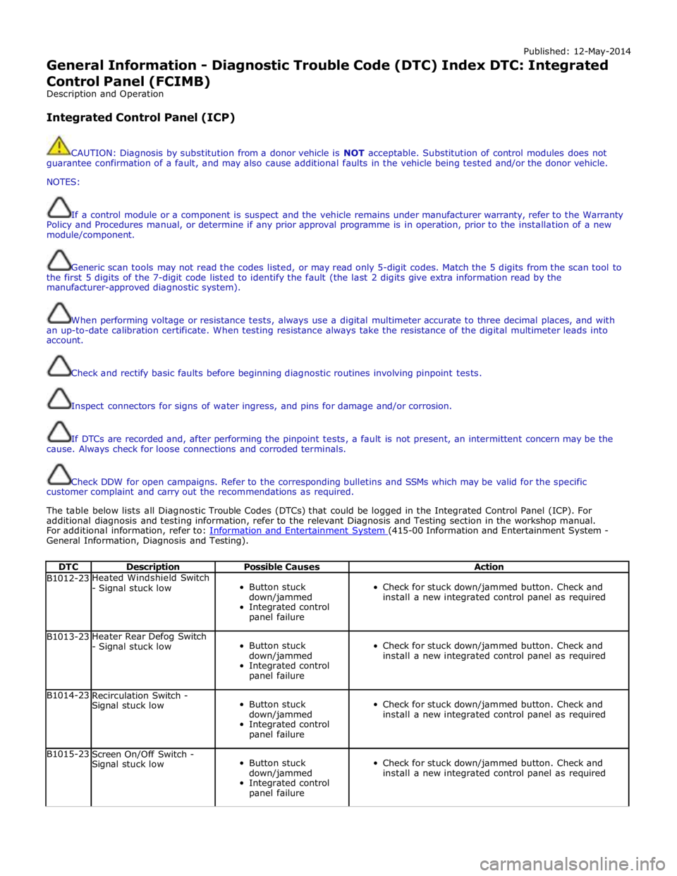
Published: 12-May-2014
General Information - Diagnostic Trouble Code (DTC) Index DTC: Integrated
Control Panel (FCIMB)
Description and Operation
Integrated Control Panel (ICP)
CAUTION: Diagnosis by substitution from a donor vehicle is NOT acceptable. Substitution of control modules does not
guarantee confirmation of a fault, and may also cause additional faults in the vehicle being tested and/or the donor vehicle.
NOTES:
If a control module or a component is suspect and the vehicle remains under manufacturer warranty, refer to the Warranty
Policy and Procedures manual, or determine if any prior approval programme is in operation, prior to the installation of a new
module/component.
Generic scan tools may not read the codes listed, or may read only 5-digit codes. Match the 5 digits from the scan tool to
the first 5 digits of the 7-digit code listed to identify the fault (the last 2 digits give extra information read by the
manufacturer-approved diagnostic system).
When performing voltage or resistance tests, always use a digital multimeter accurate to three decimal places, and with
an up-to-date calibration certificate. When testing resistance always take the resistance of the digital multimeter leads into
account.
Check and rectify basic faults before beginning diagnostic routines involving pinpoint tests.
Inspect connectors for signs of water ingress, and pins for damage and/or corrosion.
If DTCs are recorded and, after performing the pinpoint tests, a fault is not present, an intermittent concern may be the
cause. Always check for loose connections and corroded terminals.
Check DDW for open campaigns. Refer to the corresponding bulletins and SSMs which may be valid for the specific
customer complaint and carry out the recommendations as required.
The table below lists all Diagnostic Trouble Codes (DTCs) that could be logged in the Integrated Control Panel (ICP). For
additional diagnosis and testing information, refer to the relevant Diagnosis and Testing section in the workshop manual.
For additional information, refer to: Information and Entertainment System (415-00 Information and Entertainment System - General Information, Diagnosis and Testing).
DTC Description Possible Causes Action B1012-23 Heated Windshield Switch
- Signal stuck low
Button stuck
down/jammed
Integrated control
panel failure
Check for stuck down/jammed button. Check and
install a new integrated control panel as required B1013-23 Heater Rear Defog Switch
- Signal stuck low
Button stuck
down/jammed
Integrated control
panel failure
Check for stuck down/jammed button. Check and
install a new integrated control panel as required B1014-23
Recirculation Switch -
Signal stuck low
Button stuck
down/jammed
Integrated control
panel failure
Check for stuck down/jammed button. Check and
install a new integrated control panel as required B1015-23
Screen On/Off Switch -
Signal stuck low
Button stuck
down/jammed
Integrated control
panel failure
Check for stuck down/jammed button. Check and
install a new integrated control panel as required
Page 798 of 3039

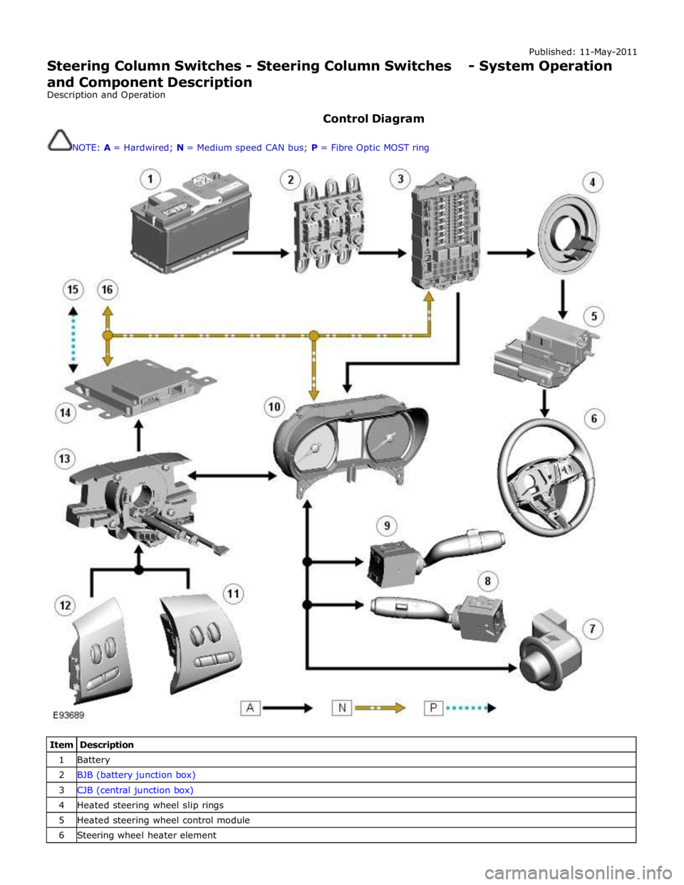
Published: 11-May-2011
Steering Column Switches - Steering Column Switches - System Operation
and Component Description
Description and Operation
Control Diagram
NOTE: A = Hardwired; N = Medium speed CAN bus; P = Fibre Optic MOST ring
Item Description 1 Battery 2 BJB (battery junction box) 3 CJB (central junction box) 4 Heated steering wheel slip rings 5 Heated steering wheel control module 6 Steering wheel heater element
Page 801 of 3039

battery power supply to be passed via the slip ring assembly in the steering wheel to the heated steering wheel control
module. The steering wheel module supplies power to the steering wheel heater element and also monitors the temperature
via a NTC (negative temperature coefficient) temperature sensor incorporated into the heater element. The control module
varies the power supply to the element to maintain the steering wheel rim at the optimum temperature.
Component Description STEERING COLUMN MULTIFUNCTION SWITCHES
The steering column multifunction switches are situated on the steering column and consists of the wiper switch, the turn
signal indicator/lighting switch and the trip computer switch.
The steering column adjustment switch is located in the steering column lower shroud on the LH side. The switch is a 4 position 'joystick' which controls reach and rake adjustment.
Steering wheel mounted switches on the LH side of the driver's airbag, control the audio and telephone functions. Switches on the RH side of the driver's airbag, control the speed control functions. For additional information, refer to:
Audio System (415-01A Information and Entertainment System, Description and Operation), Speed Control (310-03A, Description and Operation),
Speed Control (310-03B, Description and Operation),
Speed Control (310-03C, Description and Operation).
Two transmission paddle switches are located at the rear of the steering wheel.
Refer to: External Controls (307-05, Description and Operation).
LH Multifunction Switch
Item Description 1 High beam 2 Lighting control rotary switch 3 RH turn signal indicator 4 Headlamp flash 5 LH turn signal indicator 6 Trip computer function button The LH multifunction switch controls the following windshield wiper functions:
Page 803 of 3039

automatically reset once the applicable remote handset has been detected by the vehicle security systems.
STEERING WHEEL HEATER
On certain models the rim of the steering wheel contains a heater element. Operation of the heater is selected using the
Touch Screen Display (TSD).
The heater temperature is controlled by a heated steering wheel control module located within the steering wheel. Power for
the heater element is supplied to the steering wheel via 2 contacts on the clockspring and a slip ring mounted on the steering
wheel.
Page 1109 of 3039

1 Engine vent hose 2 Throttle 3 Coolant expansion tank 4 Bleed point 5 Throttle body heater hose 6 Engine oil cooler 7 Engine block heater (110 V version shown) or drain plug 8 Coolant supply/expansion hose 9 Outlet tube 10 Radiator upper hose 11 Supercharger cooling system connecting hose 12 Auxiliary radiator supply hose 13 Auxiliary radiator return hose 14 Auxiliary radiator 15 Transmission fluid cooler supply and return hoses 16 Transmission fluid cooler 17 Heater core supply and return hoses 18 Heater manifold 19 Radiator lower hose 20 Cooling fan 21 Thermostat 22 Coolant pump 23 Radiator
Page 1110 of 3039

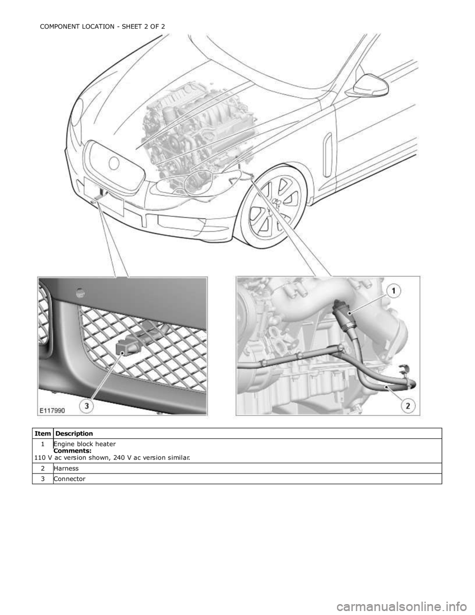
1 Engine block heater Comments:
110 V ac version shown, 240 V ac version similar. 2 Harness 3 Connector COMPONENT LOCATION - SHEET 2 OF 2
Page 1111 of 3039

Published: 11-May-2011
Engine Cooling - V8 5.0L Petrol/V8 S/C 5.0L Petrol - Engine Cooling - Overview
Description and Operation
OVERVIEW
The engine cooling system maintains the engine within an optimum temperature range under changing ambient and engine
operating conditions. The system is a pressurized expansion tank system with continuous bleeds to separate air from the
coolant and prevent the formation of air locks. The engine cooling system also provides:
Heating for:
- The passenger compartment. For additional information, refer to 412-01 Climate Control.
- The throttle body.
Cooling for:
- The engine oil cooler. For additional information, refer to 303-01F Engine - 5.0L, Vehicles With: Supercharger or
303-01E Engine - 5.0L, Vehicles Without: Supercharger.
- The transmission fluid cooler. For additional information, refer to 307-02B Transmission/Transaxle Cooling -
5.0L/3.0L Diesel.
The primary components of the engine cooling system are the:
Coolant pump.
Thermostat.
Radiator.
Auxiliary radiator (SC (supercharger) vehicles only).
Cooling fan.
Expansion tank.
Engine oil cooler.
Outlet tube and heater manifold.
Connecting hoses and pipes.