2010 JAGUAR XFR Rke module
[x] Cancel search: Rke modulePage 1957 of 3039
NOTE: When the vehicle DAB radio is first used the system will not receive any digital stations until the auto-tune
function has been completed.
Digital radio channels are organized into groups called ensembles (also known as multiplexes). Some individual channels may
also provide a number of subchannels. For example, if several sports events are being held simultaneously, the channel may
temporarily choose to broadcast each different event on a separate subchannel.
DAB is broadcast across Europe, Canada and parts of Asia. System transmission is via a terrestrial network, on two separate
broadcasting bands:
DAB band-L
DAB band III
The DAB system requires additional components to be added to the audio system. DAB antennas and a receiver are fitted to
allow reception of the service.
Operation of the DAB system is the same as the radio operation with selections made through the touch-screen and ICP to
access and navigate the system functions.
The DAB receiver is a dedicated tuner which is controlled by the ICM on the MOST ring. The receiver processes the signals from
the DAB antennas. Information is transmitted on the MOST ring and processed by the ICM. The processed information is sent
out to the power amplifier or IAM (with internal amplifier) and broadcast through the speaker system.
No configuration procedure is required if the DAB receiver is replaced. Calibration of the DAB receiver using the Jaguar
approved diagnostic equipment enables updates to be downloaded as new technology becomes available or any fault concerns
require software updates.
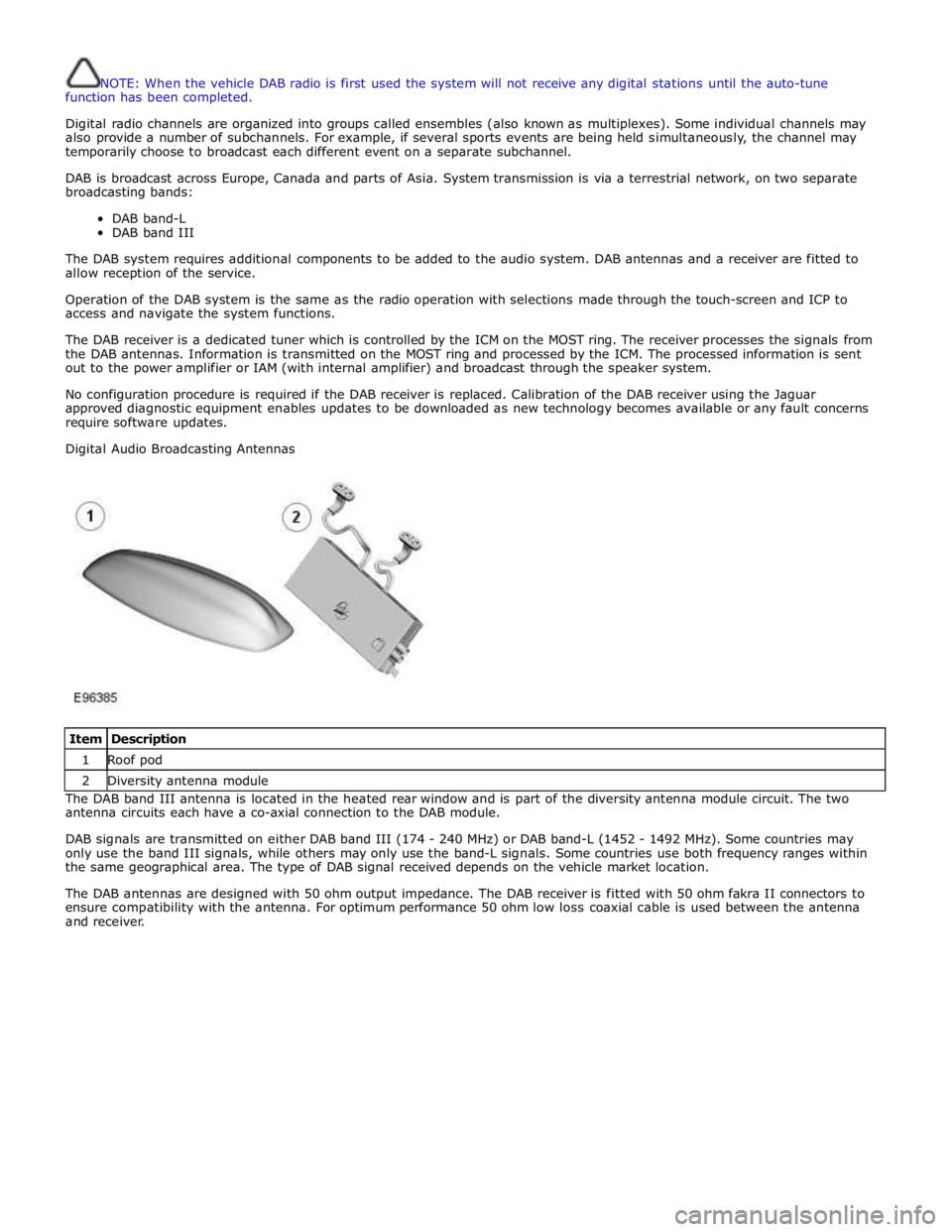
Digital Audio Broadcasting Antennas
Item Description 1 Roof pod 2 Diversity antenna module The DAB band III antenna is located in the heated rear window and is part of the diversity antenna module circuit. The two
antenna circuits each have a co-axial connection to the DAB module.
DAB signals are transmitted on either DAB band III (174 - 240 MHz) or DAB band-L (1452 - 1492 MHz). Some countries may
only use the band III signals, while others may only use the band-L signals. Some countries use both frequency ranges within
the same geographical area. The type of DAB signal received depends on the vehicle market location.
The DAB antennas are designed with 50 ohm output impedance. The DAB receiver is fitted with 50 ohm fakra II connectors to
ensure compatibility with the antenna. For optimum performance 50 ohm low loss coaxial cable is used between the antenna
and receiver.
Page 1973 of 3039

Published: 11-May-2011
Information and Entertainment System - Navigation System - Overview
Description and Operation
OVERVIEW
The navigation system provides audible and visual route guidance information to enable the driver to reach a desired
destination. The system allows the driver to choose the desired route using minor or major roads and will present 3 routes to
the driver based on user preferences. Directions to hospitals, museums, monuments and hotels are also available. The
navigation computer uses map information stored on a DVD (digital versatile disc) to determine the best route for the journey
and provide the driver with details of directions and approaching junctions.
The navigation system has various levels of user control through the Touch-screen and JaguarVoice system. System volume
adjustment can be made using the ICP (integrated control panel), Touch-screen and steering wheel controls.
There are 3 navigation system variants specific to various markets. On all systems the GPS (global positioning system) signal
is received by the GPS (global positioning system) antenna located in the roof pod antenna module.
The European navigation system includes the TMC (traffic messaging channel) function, which receives traffic information from
an FM antenna integrated into the heated rear window. On a pre-selected route the system will offer re-routing options
depending on traffic conditions.
The Japanese navigation system includes the VICS (vehicle information and communication systems) function. The VICS
(vehicle information and communication systems) supplies information to enable the navigation computer to re-route the
navigation guidance or to inform the vehicle driver of traffic conditions in the vehicles vicinity. Information is provided to the
system through an FM antenna integrated into the heated rear window and a VICS beacon located in the LH upper side of the
instrument panel.
The NAS (North American specification) variant does not include any additional traffic information systems.
The navigation system is primarily controlled from the Touch-screen which is located in the center of the instrument panel.
Control signals from the Touch-screen are sent on the MOST (media oriented systems transport) ring to the navigation
computer. The navigation computer uses a dedicated GVIF (gigabit video interface) bus to transmit video signals to the Touch-
screen.
Depending upon the audio system version fitted the navigation audio output signals are sent on the MOST (media oriented
systems transport) ring to the IAM (integrated audio module) or the power amplifier for speaker output.
Page 1977 of 3039
In addition to the standard navigation system there are two market dependant systems that supply extra information to the
navigation system and the driver. These are:
TMC (traffic message channel) (Europe only)
VICS (vehicle information and communication system) (Japan only)
The TMC (traffic message channel) is a function of the FM (frequency modulation)RDS (radio data system). The system
broadcasts real-time traffic and weather information. Data messages are received and decoded by the TMC (traffic message
channel) integral receiver and processed by the navigation computer. TMC (traffic message channel) messages can be filtered
by the navigation computer so that only those relevant to the current journey are displayed, allowing the navigation system to
offer dynamic route guidance - alerting the driver of a problem on the planned route and calculating an alternative route to
avoid the incident. All TMC (traffic message channel) events on the map can be viewed not just the ones on the calculated
route.
TMC (traffic message channel) traffic information systems conform to a global standard that has been adopted by traffic data
gatherers, information service providers, broadcasters and vehicle/receiver manufacturers.
All TMC (traffic message channel) receivers use the same list of event codes, while the location database (on the map disc)
contains both a country-specific set of location codes for the strategic European road network.
TMC (traffic message channel) traffic data is currently broadcast in many European countries.
The VICS (vehicle information and communication system) is broadcast in the Japanese market.
The VICS (vehicle information and communication system) supplies information to enable the navigation computer to re-route
the navigation guidance or to inform the vehicle driver of traffic conditions in the vehicles vicinity. Information is provided to
the system through 3 routes:
RF (radio frequency) transmission
Infra-red transmission
FM multiplex transmissions
The RF (radio frequency) transmissions are generally transmitted from road side beacons mainly on expressways. The
information transmitted is as follows:
Traffic congestion
Travel time to next intersection
Traffic conditions in surrounding areas and expressway turn offs
Traffic accidents
Speed limits
Lane regulations
Tire change
Parking availability at expressway service areas and parking areas
Infra-Red transmissions are transmitted from road side beacons on major trunk roads. The information transmitted is:
Traffic congestion and travel time
Traffic accidents
Breakdowns
Road works restrictions
Parking availability
FM transmissions are broadcast as part of the FM multiplex broadcasting system from NHK FM stations. Information transmitted is:
Traffic congestion and travel time for wide areas
Traffic accidents, road works, speed limits and lane restrictions for a wide area
Parking availability information
The traffic data is split from the normal FM transmissions by the diversity antenna module.
Selection of 'Navigation' on the Touch-screen home menu and subsequent sub-menu selection sends a control request signal to
the navigation computer on the MOST (media orientated systems transport) ring. The requested control information is
processed by the navigation computer.
If voice guidance is operational the voice signal information is relayed from the navigation computer on the MOST (media
orientated systems transport) ring to either the IAM (integrated audio unit) or Power Amplifier, dependant on equipment level,
for output on the speaker system. The navigation audio output is through the front speakers whilst the background audio, for
example radio or CD (compact disc), is played at a reduced volume on the rear speakers.
The GPS signal is available to the navigation system at all times when the vehicle ignition is switched on.
Navigation user voice commands are made using the JaguarVoice system. The ICM (information control module) processes the
analogue signal from the JaguarVoice switch into a digital signal. The digital signal is passed from the ICM (information control
module) onto the MOST (media orientated systems transport) system to the JaguarVoice control unit which is integral with the
navigation computer.
The navigation computer sends an instruction via the MOST (media orientated systems transport) ring to the IAM (integrated
audio module) to turn on the microphone facility.
The microphone is hardwired to the IAM (integrated audio module). The spoken voice command signals are relayed from the
IAM (integrated audio module) via the MOST (media orientated systems transport) ring to the navigation computer for
Page 1988 of 3039
1
2
3 frequency) si gnal s. The pos it ive fil ter i s pres ent on al l vehi cl e t ypes and market s .
The ri ght hand s i de doubl e coi l RF (radio frequency) filt er is onl y used in conjunct ion wit h t he tel evi si on antenna modules
and is connect ed acros s the heat ed rear wi ndow ground ci rcuit . If a tel evi si on s ys t e m i s not fi tt ed a fil ter i s used whi ch is
li nked di rectl y t o ground.
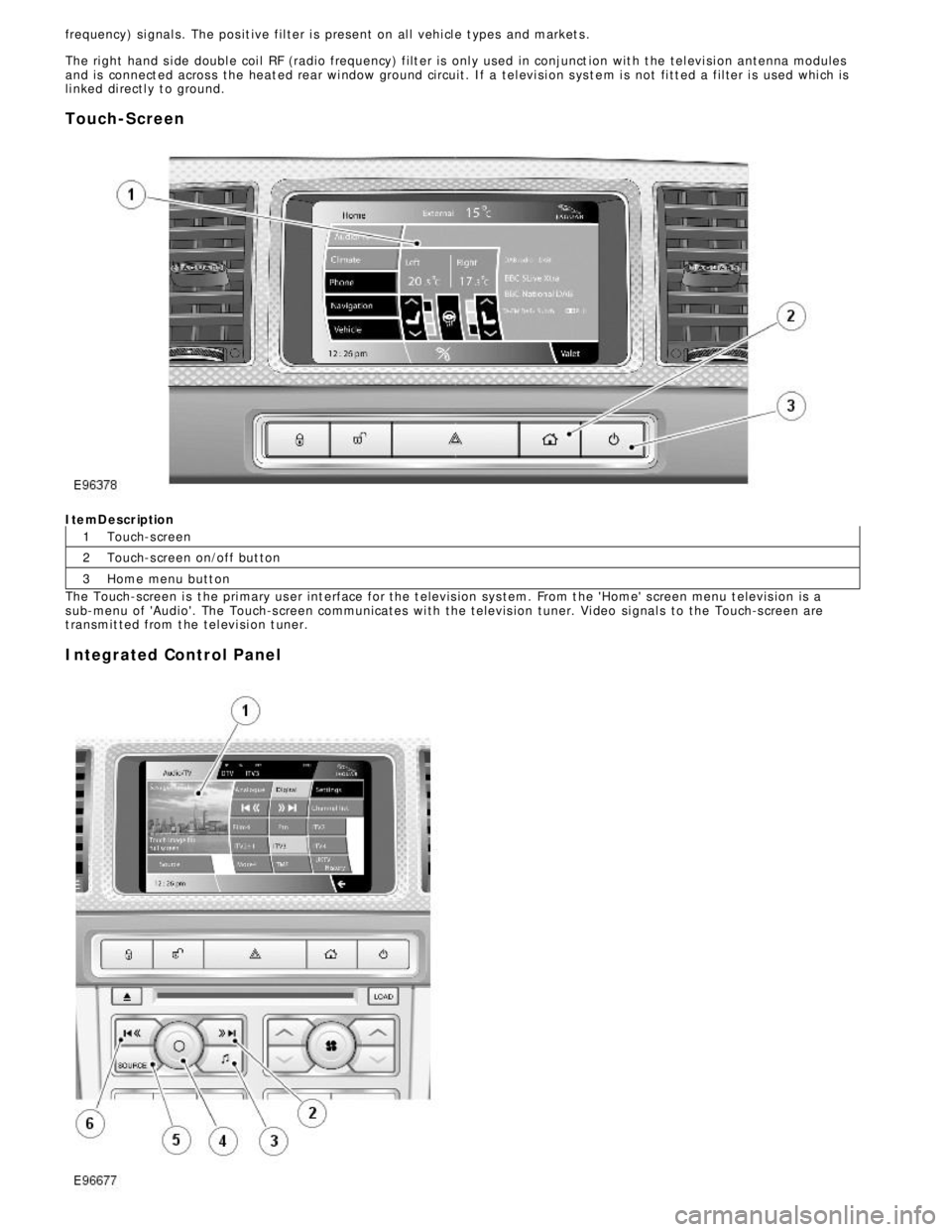
Touch-ScreenItemDescription
Touch-s creen
Touch-s creen on/off but ton
Home menu butt on
The Touch-screen i s t he pri mary us er int erface for the t elevis ion sys tem. From t he 'Home' s creen menu t elevis ion is a
s ub-menu of 'Audio'. The Touch-s creen communicates wi th the t elevis ion tuner. Vi deo si gnal s to the Touch-s creen are
t ransmit ted from t he tel evi si on t uner.
Integrated Control Panel
Page 2020 of 3039
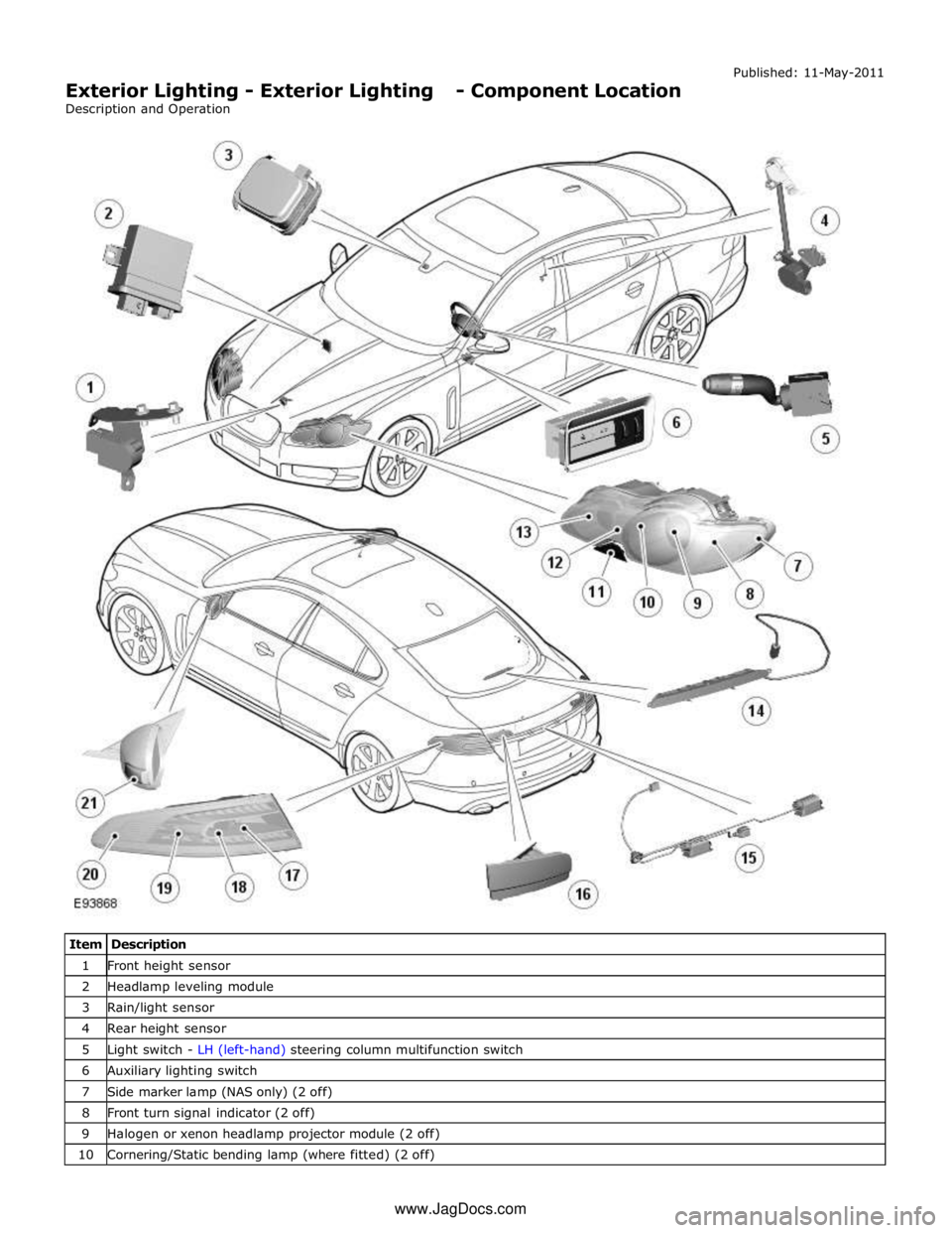
1 Front height sensor 2 Headlamp leveling module 3 Rain/light sensor 4 Rear height sensor 5 Light switch - LH (left-hand) steering column multifunction switch 6 Auxiliary lighting switch 7 Side marker lamp (NAS only) (2 off) 8 Front turn signal indicator (2 off) 9 Halogen or xenon headlamp projector module (2 off) 10 Cornering/Static bending lamp (where fitted) (2 off) www.JagDocs.com
Page 2022 of 3039
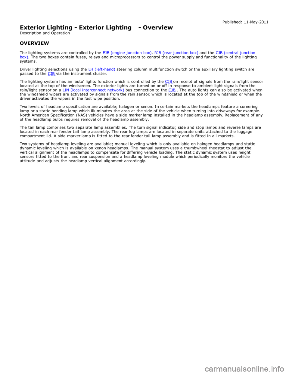
The lighting system has an 'auto' lights function which is controlled by the CJB on receipt of signals from the rain/light sensor located at the top of the windscreen. The exterior lights are turned on or off in response to ambient light signals from the
rain/light sensor on a LIN (local interconnect network) bus connection to the CJB . The auto lights can also be activated when the windshield wipers are activated by signals from the rain sensor, which is located at the top of the windshield or when the
driver activates the wipers in the fast wipe position.
Two levels of headlamp specification are available; halogen or xenon. In certain markets the headlamps feature a cornering
lamp or a static bending lamp which illuminates the area at the side of the vehicle when turning into driveways for example.
North American Specification (NAS) vehicles have a side marker lamp installed in the headlamp assembly. Replacement of any
of the headlamp bulbs requires removal of the headlamp assembly.
The tail lamp comprises two separate lamp assemblies. The turn signal indicator, side and stop lamps and reverse lamps are
located in each rear fender tail lamp assembly. The rear fog lamps are located in separate units attached to the luggage
compartment lid. A side marker lamp is fitted to the rear fender tail lamp assembly and is fitted in all markets.
Two systems of headlamp leveling are available; manual leveling which is only available on halogen headlamps and static
dynamic leveling which is available on xenon headlamps. The manual system uses a thumbwheel rheostat to adjust the
vertical alignment of the headlamps to compensate for differing vehicle loading. The static dynamic system uses height
sensors fitted to the front and rear suspension and a headlamp leveling module which periodically monitors the vehicle
attitude and adjusts the headlamp vertical alignment accordingly.
Page 2026 of 3039
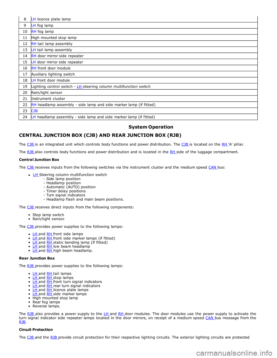
8 LH licence plate lamp 9 LH fog lamp 10 RH fog lamp 11 High mounted stop lamp 12 RH tail lamp assembly 13 LH tail lamp assembly 14 RH door mirror side repeater 15 LH door mirror side repeater 16 RH front door module 17 Auxiliary lighting switch 18 LH front door module 19 Lighting control switch - LH steering column multifunction switch 20 Rain/light sensor 21 Instrument cluster 22 RH headlamp assembly - side lamp and side marker lamp (if fitted) 23 CJB 24 LH headlamp assembly - side lamp and side marker lamp (if fitted)
System Operation CENTRAL JUNCTION BOX (CJB) AND REAR JUNCTION BOX (RJB)
The CJB is an integrated unit which controls body functions and power distribution. The CJB is located on the RH 'A' pillar. The RJB also controls body functions and power distribution and is located in the RH side of the luggage compartment. Central Junction Box
The CJB receives inputs from the following switches via the instrument cluster and the medium speed CAN bus: LH Steering column multifunction switch - Side lamp position
- Headlamp position
- Automatic (AUTO) position
- Timer delay positions
- Turn signal indicators
- Headlamp flash and main beam positions.
The CJB receives direct inputs from the following components: Stop lamp switch
Rain/light sensor.
The CJB provides power supplies to the following lamps:
LH and RH front side lamps LH and RH front side marker lamps (if fitted) LH and RH static bending lamp (if fitted) LH and RH low beam headlamp LH and RH high beam headlamp. Rear Junction Box
The RJB provides power supplies to the following lamps:
LH and RH tail lamps LH and RH stop lamps LH and RH front turn signal indicators LH and RH rear turn signal indicators LH and RH licence plate lamps LH and RH side marker lamps High mounted stop lamp
Rear fog lamps
Reverse lamps.
The RJB also provides a power supply to the LH and RH door modules. The door modules use the power supply to activate the turn signal indicator side repeater lamps located in the door mirrors, on receipt of a medium speed CAN bus message from the RJB. Circuit Protection
The CJB and the RJB provide circuit protection for their respective lighting circuits. The exterior lighting circuits are protected
Page 2028 of 3039
resistors. The returned signal voltage is detected by the instrument cluster which outputs a message on the medium speed
CAN bus to the CJB to activate the headlamps. The reference voltage to the auto headlamp exit delay switch is routed through 4 resistors which is detected by the instrument cluster which outputs a message on the medium speed CAN bus to the CJB that auto headlamp or exit delay has not been selected.
AUTOLAMPS - When the lighting control switch is in the auto headlamp position, the reference voltage flows through 4 of the
resistors. The returned signal voltage is detected by the instrument cluster which outputs a message on the medium speed
CAN bus to the CJB to activate the autolamp function. The reference voltage to the autolamp exit delay switch is routed through 4 resistors which is detected by the instrument cluster which outputs a message on the medium speed CAN bus to the CJB that auto headlamp has been selected.
AUXILIARY LIGHTING SWITCH
Headlamp Leveling Rotary Thumbwheel (Halogen headlamps only)
A power supply is passed to the headlamp leveling thumbwheel from the ignition relay in the EJB. Depending on the position of the thumbwheel, the voltage passes through 1, 2 or 3 resistors connected in series. The voltage through the resistors is
passed to the headlamp leveling motor controller in each headlamp. The received voltage is determined as a request for the
appropriate level position and the controller powers the headlamp level motors to the applicable position for each headlamp.
Rear Fog Lamp Switch
The instrument cluster supplies a reference voltage and return to the rear fog lamp switch. The fog lamp switch is a
non-latching, momentary switch.
When the fog lamp switch is off the reference voltage is passed through a 1Kohm resistor. The voltage through the resistor is
returned to the instrument cluster that determines that no request for fog lamp operation has been made.
When the driver presses the fog lamp switch, the reference voltage is passed through a 330 ohm resistor. The change is return
voltage is sensed by the instrument cluster which determines fog lamp operation has been requested. The instrument cluster
transmits a medium speed CAN bus signal to the RJB providing the lighting control switch is in the correct position. The RJB reacts to the message and provides a power supply to the 3 LED (light emitting diode)'s in each rear fog lamp. A fog lamp
warning lamp in the instrument cluster will also be illuminated when the fog lamps are operating.
The RJB will only activate the rear fog lamps if the headlamps are selected on or are active with auto headlamp activation. When the headlamps are turned off the fog lamps are also turned off. When the headlamps are next switched on, the fog
lamps will not be activated until the driver requests fog lamp operation.
NOTE: The fog lamps do operate when DRL (daytime running lamps) are active.
HEADLAMP LEVELING
Manual Headlamp Leveling - Halogen headlamps only
A power supply is passed to the headlamp leveling motor in each headlamp from the ignition relay in the EJB. When a signal voltage is received from the headlamp leveling rotary thumbwheel, the headlamp leveling motor controller in each headlamp
uses the power supply to operate the motors and move the headlamp to the requested position.
Static Dynamic Headlamp Leveling - Xenon headlamps only
The headlamp leveling module receives a power supply from the ignition relay in the EJB. The same power supply is also supplied to the headlamp leveling motor in each headlamp assembly. The front and rear height sensors are connected to the
headlamp leveling module and receive a power and ground from the module. Each sensor has a signal line to the headlamp
leveling module to return height information to the module. The module uses the height signals from the sensors to calculate
the vehicle attitude and supplies a signal to each motor to power the headlamp to the required position.
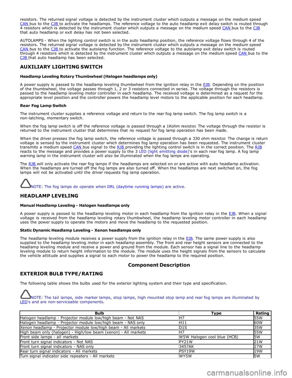
EXTERIOR BULB TYPE/RATING Component Description
The following table shows the bulbs used for the exterior lighting system and their type and specification.
NOTE: The tail lamps, side marker lamps, stop lamps, high mounted stop lamp and rear fog lamps are illuminated by
LED's and are non-serviceable components.
Bulb Type Rating Halogen headlamp - Projector module low/high beam - Not NAS H7 55W Halogen headlamp - Projector module low/high beam - NAS only H11 60W Xenon headlamp - Projector module low/high beam - All markets D1S 35W High beam only (halogen) - High/low beam (xenon) - All markets H7 55W Front side lamps - all markets W5W Halogen cool blue (HCB) 5W Front turn signal indicators - Not NAS PY21W 21W Front turn signal indicators - NAS only 3457AK 27W Rear turn signal indicators - All markets PSY19W 19W Turn signal indicator side repeaters - All markets WY5W 5W