2010 JAGUAR XFR Electrical
[x] Cancel search: ElectricalPage 1939 of 3039
Published: 11-May-2011
Information and Entertainment System - General Information - Navigation
System
Diagnosis and Testing
Principle of Operation
For a detailed description of the Navigation System, refer to the relevant Description and Operation sections in the workshop
manual. REFER to: (415-01 Information and Entertainment System)
Navigation System (Description and Operation),
Navigation System (Description and Operation),
Navigation System (Description and Operation),
Video System (Description and Operation),
Video System (Description and Operation),
Video System (Description and Operation).
Inspection and Verification
CAUTION: Diagnosis by substitution from a donor vehicle is NOT acceptable. Substitution of control modules does not
guarantee confirmation of a fault, and may also cause additional faults in the vehicle being tested and/or the donor vehicle.
1. Verify the customer concern.
2. Visually inspect for obvious signs of damage and system integrity.
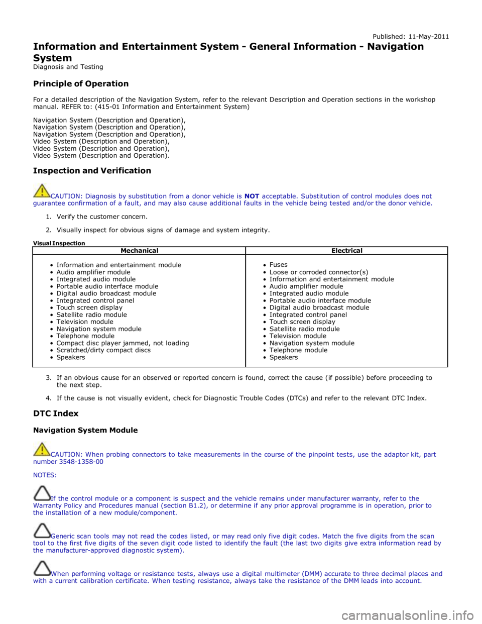
Visual Inspection
Mechanical Electrical
Information and entertainment module
Audio amplifier module
Integrated audio module
Portable audio interface module
Digital audio broadcast module
Integrated control panel
Touch screen display
Satellite radio module
Television module
Navigation system module
Telephone module
Compact disc player jammed, not loading
Scratched/dirty compact discs
Speakers
Fuses
Loose or corroded connector(s)
Information and entertainment module
Audio amplifier module
Integrated audio module
Portable audio interface module
Digital audio broadcast module
Integrated control panel
Touch screen display
Satellite radio module
Television module
Navigation system module
Telephone module
Speakers
3. If an obvious cause for an observed or reported concern is found, correct the cause (if possible) before proceeding to
the next step.
4. If the cause is not visually evident, check for Diagnostic Trouble Codes (DTCs) and refer to the relevant DTC Index.
DTC Index
Navigation System Module
CAUTION: When probing connectors to take measurements in the course of the pinpoint tests, use the adaptor kit, part
number 3548-1358-00
NOTES:
If the control module or a component is suspect and the vehicle remains under manufacturer warranty, refer to the
Warranty Policy and Procedures manual (section B1.2), or determine if any prior approval programme is in operation, prior to
the installation of a new module/component.
Generic scan tools may not read the codes listed, or may read only five digit codes. Match the five digits from the scan
tool to the first five digits of the seven digit code listed to identify the fault (the last two digits give extra information read by
the manufacturer-approved diagnostic system).
When performing voltage or resistance tests, always use a digital multimeter (DMM) accurate to three decimal places and
with a current calibration certificate. When testing resistance, always take the resistance of the DMM leads into account.
Page 1940 of 3039
Check and rectify basic faults before beginning diagnostic routines involving pinpoint tests.
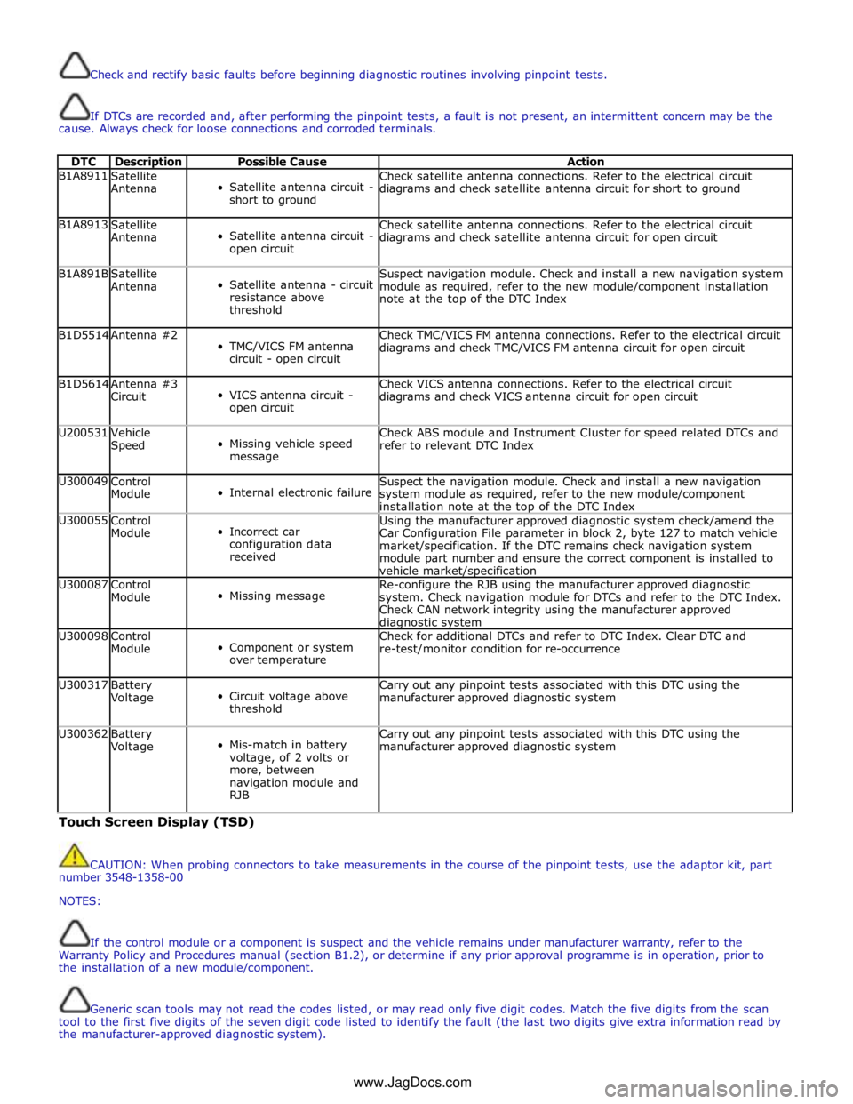
If DTCs are recorded and, after performing the pinpoint tests, a fault is not present, an intermittent concern may be the
cause. Always check for loose connections and corroded terminals.
DTC Description Possible Cause Action B1A8911
Satellite
Antenna
Satellite antenna circuit -
short to ground Check satellite antenna connections. Refer to the electrical circuit
diagrams and check satellite antenna circuit for short to ground B1A8913
Satellite
Antenna
Satellite antenna circuit -
open circuit Check satellite antenna connections. Refer to the electrical circuit
diagrams and check satellite antenna circuit for open circuit B1A891B
Satellite
Antenna
Satellite antenna - circuit
resistance above
threshold Suspect navigation module. Check and install a new navigation system
module as required, refer to the new module/component installation
note at the top of the DTC Index B1D5514 Antenna #2
TMC/VICS FM antenna
circuit - open circuit Check TMC/VICS FM antenna connections. Refer to the electrical circuit
diagrams and check TMC/VICS FM antenna circuit for open circuit B1D5614
Antenna #3
Circuit
VICS antenna circuit -
open circuit Check VICS antenna connections. Refer to the electrical circuit
diagrams and check VICS antenna circuit for open circuit U200531
Vehicle
Speed
Missing vehicle speed
message Check ABS module and Instrument Cluster for speed related DTCs and
refer to relevant DTC Index U300049
Control
Module
Internal electronic failure Suspect the navigation module. Check and install a new navigation
system module as required, refer to the new module/component
installation note at the top of the DTC Index U300055
Control
Module
Incorrect car
configuration data
received Using the manufacturer approved diagnostic system check/amend the
Car Configuration File parameter in block 2, byte 127 to match vehicle
market/specification. If the DTC remains check navigation system
module part number and ensure the correct component is installed to
vehicle market/specification U300087
Control
Module
Missing message Re-configure the RJB using the manufacturer approved diagnostic
system. Check navigation module for DTCs and refer to the DTC Index.
Check CAN network integrity using the manufacturer approved diagnostic system U300098
Control
Module
Component or system
over temperature Check for additional DTCs and refer to DTC Index. Clear DTC and
re-test/monitor condition for re-occurrence U300317
Battery
Voltage
Circuit voltage above
threshold Carry out any pinpoint tests associated with this DTC using the
manufacturer approved diagnostic system U300362
Battery
Voltage
Mis-match in battery
voltage, of 2 volts or
more, between
navigation module and
RJB Carry out any pinpoint tests associated with this DTC using the
manufacturer approved diagnostic system Touch Screen Display (TSD)
CAUTION: When probing connectors to take measurements in the course of the pinpoint tests, use the adaptor kit, part
number 3548-1358-00
NOTES:
If the control module or a component is suspect and the vehicle remains under manufacturer warranty, refer to the
Warranty Policy and Procedures manual (section B1.2), or determine if any prior approval programme is in operation, prior to
the installation of a new module/component.
Generic scan tools may not read the codes listed, or may read only five digit codes. Match the five digits from the scan
tool to the first five digits of the seven digit code listed to identify the fault (the last two digits give extra information read by
the manufacturer-approved diagnostic system).
www.JagDocs.com
Page 1941 of 3039
When performing voltage or resistance tests, always use a digital multimeter (DMM) accurate to three decimal places and
with a current calibration certificate. When testing resistance, always take the resistance of the DMM leads into account.
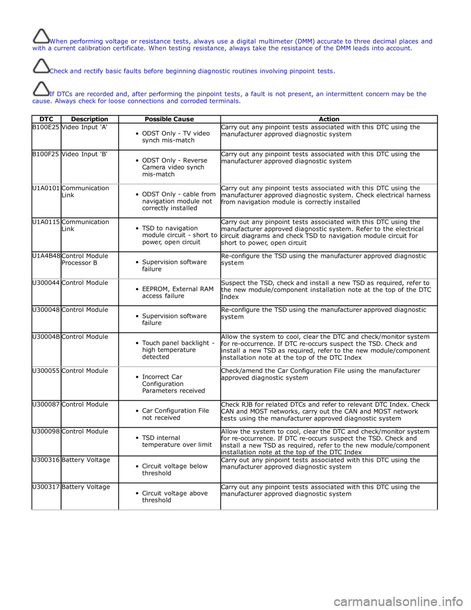
Check and rectify basic faults before beginning diagnostic routines involving pinpoint tests.
If DTCs are recorded and, after performing the pinpoint tests, a fault is not present, an intermittent concern may be the
cause. Always check for loose connections and corroded terminals.
DTC Description Possible Cause Action B100E25 Video Input 'A'
ODST Only - TV video
synch mis-match Carry out any pinpoint tests associated with this DTC using the
manufacturer approved diagnostic system B100F25 Video Input 'B'
ODST Only - Reverse
Camera video synch
mis-match Carry out any pinpoint tests associated with this DTC using the
manufacturer approved diagnostic system U1A0101
Communication
Link
ODST Only - cable from
navigation module not
correctly installed Carry out any pinpoint tests associated with this DTC using the
manufacturer approved diagnostic system. Check electrical harness
from navigation module is correctly installed U1A0115
Communication
Link
TSD to navigation
module circuit - short to
power, open circuit Carry out any pinpoint tests associated with this DTC using the
manufacturer approved diagnostic system. Refer to the electrical
circuit diagrams and check TSD to navigation module circuit for
short to power, open circuit U1A4B48
Control Module
Processor B
Supervision software
failure Re-configure the TSD using the manufacturer approved diagnostic
system U300044 Control Module
EEPROM, External RAM
access failure Suspect the TSD, check and install a new TSD as required, refer to
the new module/component installation note at the top of the DTC
Index U300048 Control Module
Supervision software
failure Re-configure the TSD using the manufacturer approved diagnostic
system U30004B Control Module
Touch panel backlight -
high temperature
detected Allow the system to cool, clear the DTC and check/monitor system
for re-occurrence. If DTC re-occurs suspect the TSD. Check and
install a new TSD as required, refer to the new module/component
installation note at the top of the DTC Index U300055 Control Module
Incorrect Car
Configuration
Parameters received Check/amend the Car Configuration File using the manufacturer
approved diagnostic system U300087 Control Module
Car Configuration File
not received Check RJB for related DTCs and refer to relevant DTC Index. Check
CAN and MOST networks, carry out the CAN and MOST network
tests using the manufacturer approved diagnostic system U300098 Control Module
TSD internal
temperature over limit Allow the system to cool, clear the DTC and check/monitor system
for re-occurrence. If DTC re-occurs suspect the TSD. Check and
install a new TSD as required, refer to the new module/component
installation note at the top of the DTC Index U300316 Battery Voltage
Circuit voltage below
threshold Carry out any pinpoint tests associated with this DTC using the
manufacturer approved diagnostic system U300317 Battery Voltage
Circuit voltage above
threshold Carry out any pinpoint tests associated with this DTC using the
manufacturer approved diagnostic system
Page 1948 of 3039
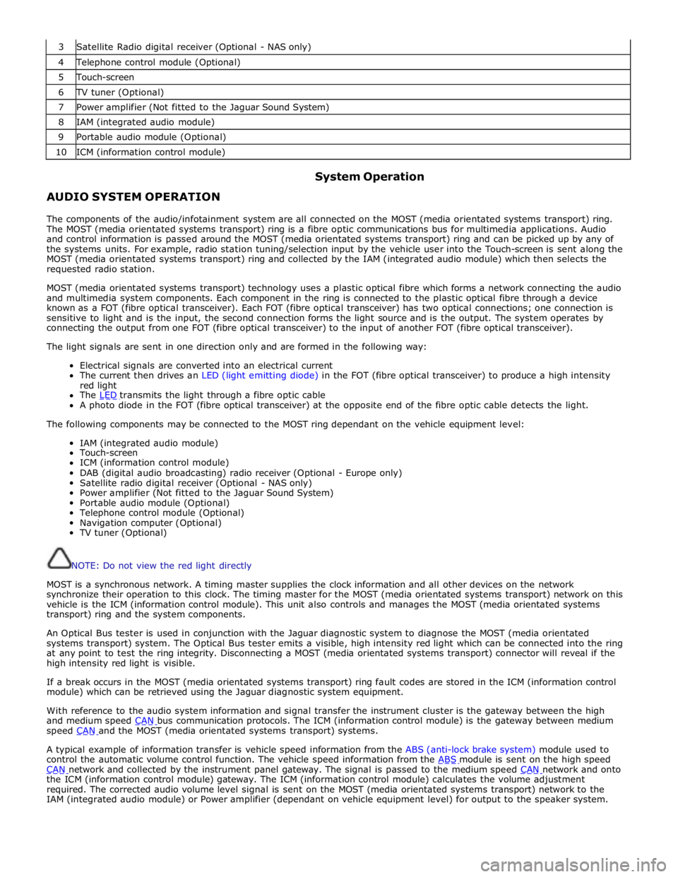
3 Satellite Radio digital receiver (Optional - NAS only) 4 Telephone control module (Optional) 5 Touch-screen 6 TV tuner (Optional) 7 Power amplifier (Not fitted to the Jaguar Sound System) 8 IAM (integrated audio module) 9 Portable audio module (Optional) 10 ICM (information control module)
AUDIO SYSTEM OPERATION System Operation
The components of the audio/infotainment system are all connected on the MOST (media orientated systems transport) ring.
The MOST (media orientated systems transport) ring is a fibre optic communications bus for multimedia applications. Audio
and control information is passed around the MOST (media orientated systems transport) ring and can be picked up by any of
the systems units. For example, radio station tuning/selection input by the vehicle user into the Touch-screen is sent along the
MOST (media orientated systems transport) ring and collected by the IAM (integrated audio module) which then selects the
requested radio station.
MOST (media orientated systems transport) technology uses a plastic optical fibre which forms a network connecting the audio
and multimedia system components. Each component in the ring is connected to the plastic optical fibre through a device
known as a FOT (fibre optical transceiver). Each FOT (fibre optical transceiver) has two optical connections; one connection is
sensitive to light and is the input, the second connection forms the light source and is the output. The system operates by
connecting the output from one FOT (fibre optical transceiver) to the input of another FOT (fibre optical transceiver).
The light signals are sent in one direction only and are formed in the following way:
Electrical signals are converted into an electrical current
The current then drives an LED (light emitting diode) in the FOT (fibre optical transceiver) to produce a high intensity
red light
The LED transmits the light through a fibre optic cable A photo diode in the FOT (fibre optical transceiver) at the opposite end of the fibre optic cable detects the light.
The following components may be connected to the MOST ring dependant on the vehicle equipment level:
IAM (integrated audio module)
Touch-screen
ICM (information control module)
DAB (digital audio broadcasting) radio receiver (Optional - Europe only)
Satellite radio digital receiver (Optional - NAS only)
Power amplifier (Not fitted to the Jaguar Sound System)
Portable audio module (Optional)
Telephone control module (Optional)
Navigation computer (Optional)
TV tuner (Optional)
NOTE: Do not view the red light directly
MOST is a synchronous network. A timing master supplies the clock information and all other devices on the network
synchronize their operation to this clock. The timing master for the MOST (media orientated systems transport) network on this
vehicle is the ICM (information control module). This unit also controls and manages the MOST (media orientated systems
transport) ring and the system components.
An Optical Bus tester is used in conjunction with the Jaguar diagnostic system to diagnose the MOST (media orientated
systems transport) system. The Optical Bus tester emits a visible, high intensity red light which can be connected into the ring
at any point to test the ring integrity. Disconnecting a MOST (media orientated systems transport) connector will reveal if the
high intensity red light is visible.
If a break occurs in the MOST (media orientated systems transport) ring fault codes are stored in the ICM (information control
module) which can be retrieved using the Jaguar diagnostic system equipment.
With reference to the audio system information and signal transfer the instrument cluster is the gateway between the high
and medium speed CAN bus communication protocols. The ICM (information control module) is the gateway between medium speed CAN and the MOST (media orientated systems transport) systems.
A typical example of information transfer is vehicle speed information from the ABS (anti-lock brake system) module used to
control the automatic volume control function. The vehicle speed information from the ABS module is sent on the high speed CAN network and collected by the instrument panel gateway. The signal is passed to the medium speed CAN network and onto the ICM (information control module) gateway. The ICM (information control module) calculates the volume adjustment
required. The corrected audio volume level signal is sent on the MOST (media orientated systems transport) network to the
IAM (integrated audio module) or Power amplifier (dependant on vehicle equipment level) for output to the speaker system.
Page 2010 of 3039
Published: 23-Jan-2012
Information and Entertainment System - DTC: Audio Input Control Module - Audio Input Control Module
Diagnosis and Testing
Principle of Operation
This section of the manual concerns diagnostic procedures for the Dension audio input control module. For a detailed
description of the information and entertainment system, refer to the relevant description and operation sections in the
workshop manual
Inspection and Verification
CAUTION: Diagnosis by substitution from a donor vehicle is NOT acceptable. Substitution of control modules does not
guarantee confirmation of a fault, and may also cause additional faults in the vehicle being tested and/or the donor vehicle
1. Verify the customer concern
2. Visually inspect for obvious signs of damage and system integrity
Visual Inspection
Mechanical Electrical
Audio input control module
Audio amplifier module
Integrated audio module
Integrated control panel
Touch screen display
Loudspeakers
Fuses
Loose or corroded connector(s)
Audio amplifier module
Integrated audio module
Integrated control panel
Touch screen display
Loudspeakers
3. If an obvious cause for an observed or reported concern is found, correct the cause (if possible) before proceeding to
the next step
4. If the cause is not visually evident, check for diagnostic trouble codes and refer to the relevant diagnostic trouble codes
index
Audio Input Control Module Diagnostics
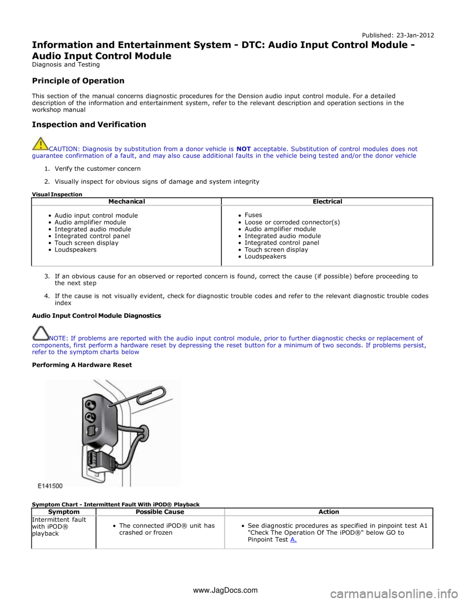
NOTE: If problems are reported with the audio input control module, prior to further diagnostic checks or replacement of
components, first perform a hardware reset by depressing the reset button for a minimum of two seconds. If problems persist,
refer to the symptom charts below
Performing A Hardware Reset
Symptom Chart - Intermittent Fault With iPOD® Playback
Symptom Possible Cause Action Intermittent fault
with iPOD®
playback
The connected iPOD® unit has
crashed or frozen
See diagnostic procedures as specified in pinpoint test A1
"Check The Operation Of The iPOD®" below GO to
Pinpoint Test A. www.JagDocs.com
Page 2032 of 3039
15 Xenon igniter unit and bulb 16 Xenon igniter electrical connector 17 Cornering/static bending lamp bulb (if fitted) 18 Side lamp bulb 19 High beam headlamp bulb 20 Cover - Side lamp, cornering/static bending lamp (if fitted) and high beam headlamp bulbs 21 Electrical connector Bi-Xenon Headlamp
The bi-xenon headlamp uses a projector lens, similar to the halogen headlamp. The projector module comprises an ellipsoidal
lens and a reflector. The projector reflector collects the light produced by the halogen bulb and projects the light into a focal
plane containing a shield. The contour of the shield is projected onto the road by the lens. A complex surface reflector is used
for the halogen fill in high beam lamp. This type of reflector is divided into separate parabolic segments, with each segment
having a different focal length. The low and high beam bulbs are quartz halogen H7, with a rating of 55W. The bulbs are
retained in the headlamp unit with conventional wire retaining clips.
A tourist lever mechanism is located on the right hand side of the projector module. This mechanism moves a flap to blank off
a portion of the beam spread to enable the vehicle to be driven in opposite drive hand markets without applying blanking
decals to the headlamp lens. The beam is changed by removing the access cover at the rear of the lamp assembly and moving
a small lever located near the bulb holder, at the side of the projector.
NOTE: The tourist lever is not fitted to NAS vehicles.
WARNING: The Xenon system generates up to 30000 volts and contact with this voltage could lead to fatality. Make sure
that the headlamps are switched off before working on the system.
The following safety precautions must be adhered to when working on the xenon low beam headlamp system:
DO NOT attempt any procedures on the xenon headlamps when the lights are switched on.
Handling of the D1S xenon bulb must be performed using suitable protective equipment; for example gloves and
goggles. The glass part of the bulb must not be touched.
Xenon bulbs must be disposed of as hazardous waste.
Only operate the bulb in a mounted condition in the projector module installed in the headlamp.
The xenon headlamp is known as 'bi-xenon' because it operates as both a low and high beam headlamp unit. The xenon lamp,
or High Intensity Discharge (HID) lamp as they are sometimes referred to, comprises an ellipsoidal lens with a solenoid
controlled shutter to change the beam output from low to high beam.
NOTE: If the lighting control switch is in the 'off' position, both the xenon lamp and the halogen high beam lamp will
operate when the high beam 'flash' function is operated.
The xenon headlamp system is controlled by the CJB using a control module for each headlamp and an igniter. The control modules and the igniters provide the regulated power supply required to illuminate the bulbs through their start-up phases of
operation.
The xenon headlamp is a self contained unit located within the headlamp assembly. The unit comprises a reflector, an adaptor
ring, the lens, a shutter controller and the xenon bulb, which together forms an assembly known as the projector module. The
reflector is curved and provides the mounting point for the xenon bulb. The bulb locates in a keyway to ensure the correct
alignment in the reflector and is secured by a plastic mounting ring. The bulb is an integral component of the igniter and is
electrically connected by a connector located in the igniter unit.
The shutter controller is a solenoid which operates the shutter mechanism via a lever. The shutter is used to change the beam
projection from low beam to high beam and vice versa.
The xenon bulbs illuminate when an arc of electrical current is established between 2 electrodes within the bulb. The xenon
gas sealed in the bulb reacts to the electrical excitation and the heat generated by the current flow to produce the
characteristic blue/white light.
To operate at full efficiency, the xenon bulb goes through 3 full stages of operation before full output for continuous operation
is achieved. The 3 phases are; start-up phase, warm-up phase and continuous phase.
In the start-up phase, the bulb requires an initial high voltage starting pulse of up to 30000 volts to establish the arc. This is
produced by the igniter. The warm-up phase begins once the arc is established. The xenon control module regulates the supply
to the bulb to 2.6A which gives a lamp output of 75W. During this phase, the xenon gas begins to illuminate brightly and the
environment within the bulb stabilizes, ensuring a continual current flow between the electrodes. When the warm-up phase is
complete, the xenon control module changes to continuous phase. The supply voltage to the bulb is reduced and the operating
power required for continual operation is reduced to 35W. The process from start-up to continuous phase is completed in a very
short time.
The xenon control modules (one per headlamp) receive an operating voltage from the CJB when the headlamps are switched on. The modules regulate the power supply required through the phases of start-up.
The igniters (one per headlamp) generate the initial high voltage required to establish the arc. The igniters have integral coils
which generate high voltage pulses required for start-up. Once the xenon bulbs are operating, the igniters provide a closed
circuit for the regulated power supply from the control modules.
Page 2035 of 3039
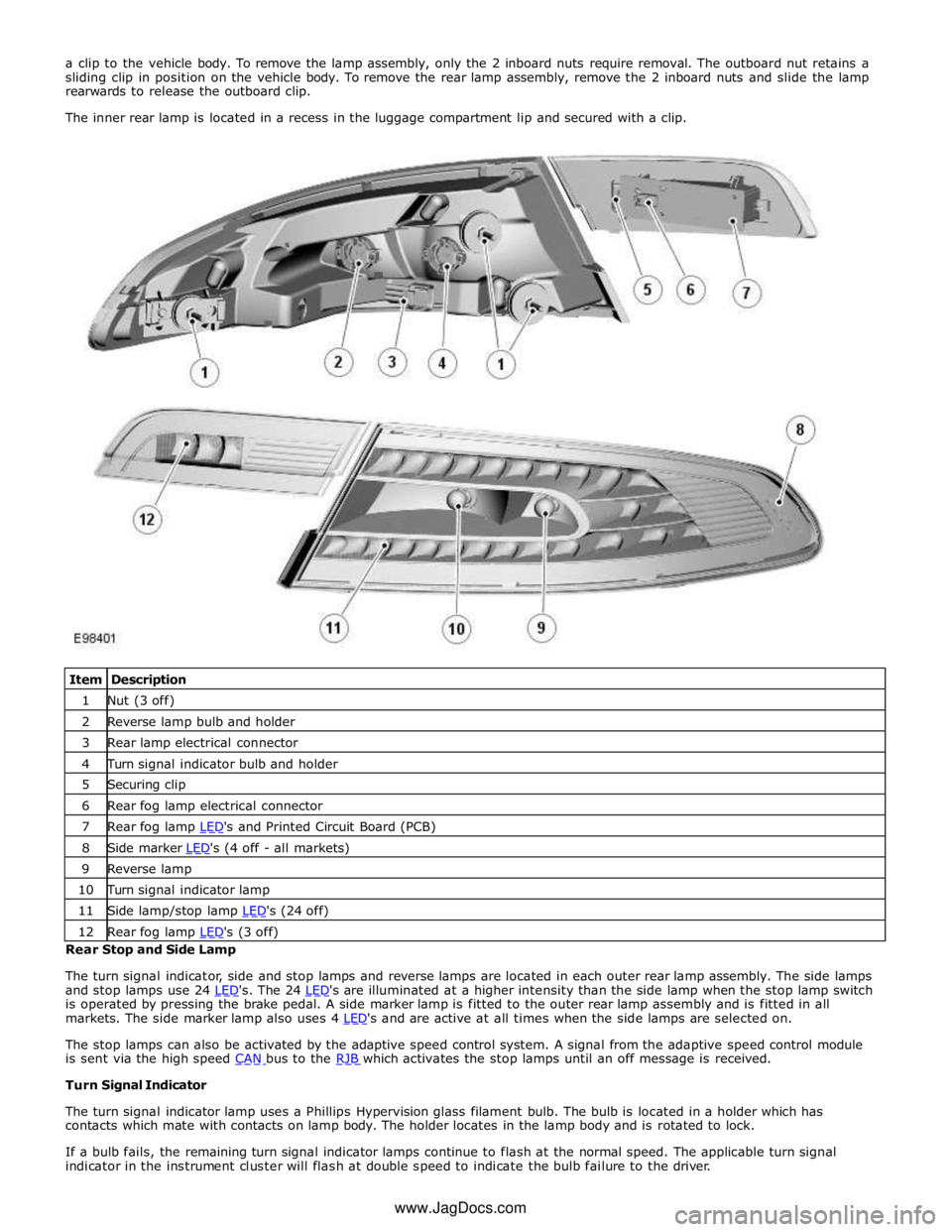
1 Nut (3 off) 2 Reverse lamp bulb and holder 3 Rear lamp electrical connector 4 Turn signal indicator bulb and holder 5 Securing clip 6 Rear fog lamp electrical connector 7 Rear fog lamp LED's and Printed Circuit Board (PCB) 8 Side marker LED's (4 off - all markets) 9 Reverse lamp 10 Turn signal indicator lamp 11 Side lamp/stop lamp LED's (24 off) 12 Rear fog lamp LED's (3 off) Rear Stop and Side Lamp
The turn signal indicator, side and stop lamps and reverse lamps are located in each outer rear lamp assembly. The side lamps
and stop lamps use 24 LED's. The 24 LED's are illuminated at a higher intensity than the side lamp when the stop lamp switch is operated by pressing the brake pedal. A side marker lamp is fitted to the outer rear lamp assembly and is fitted in all
markets. The side marker lamp also uses 4 LED's and are active at all times when the side lamps are selected on.
The stop lamps can also be activated by the adaptive speed control system. A signal from the adaptive speed control module
is sent via the high speed CAN bus to the RJB which activates the stop lamps until an off message is received. Turn Signal Indicator
The turn signal indicator lamp uses a Phillips Hypervision glass filament bulb. The bulb is located in a holder which has
contacts which mate with contacts on lamp body. The holder locates in the lamp body and is rotated to lock.
If a bulb fails, the remaining turn signal indicator lamps continue to flash at the normal speed. The applicable turn signal
indicator in the instrument cluster will flash at double speed to indicate the bulb failure to the driver. www.JagDocs.com
Page 2037 of 3039
Exterior Lighting - Headlamps
Diagnosis and Testing
Principles of Operation Published: 11-Jul-2014
For a detailed description of the exterior lighting system, refer to the relevant Description and Operation section in the
workshop manual. REFER to: (417-01 Exterior Lighting)
Exterior Lighting (Description and Operation), Exterior Lighting (Description and Operation), Exterior Lighting (Description and Operation).
Safety Information
WARNINGS:
The Xenon Headlamp system generates up to 28,000 volts. Make sure that the headlamps are switched off before
working on the system. Failure to follow this instruction may lead to fatality.
The following safety precautions must be followed when working on the Xenon Headlamp system:
DO NOT attempt any procedures on the Xenon Headlamps or circuits when the system is energized.
Handling of the xenon bulb must be performed using suitable protective equipment, e.g. gloves and goggles. The glass
part of the bulb must not be touched.
Only operate the lamp in a mounted condition in the reflector.
All safety procedures and precautions must be followed to prevent personal injury.
CAUTION: Xenon bulbs must be disposed of as hazardous waste.
There are instructions on the correct procedures for Xenon Headlamp System repairs in the manual, refer to section 100-00 -
General Information, Standard Workshop Practices of the workshop manual.
Inspection and Verification
CAUTION: Diagnosis by substitution from a donor vehicle is NOT acceptable. Substitution of control modules does not
guarantee confirmation of a fault, and may also cause additional faults in the vehicle being tested and/or the donor vehicle.
1. Verify the customer concern.
2. Visually inspect for obvious signs of damage.
3. If an obvious cause for an observed or reported concern is found, correct the cause (if possible) before proceeding to
the next step.
4. If the cause is not visually evident, check for Diagnostic Trouble Codes (DTCs) and refer to DTC Index.
Symptom Chart
Symptom Possible Causes Action Low beam lamp(s)
inoperative
Bulb failure
Fuse(s) blown
Circuit fault
Lighting control switch
fault
Left-hand steering
column multifunction
switch fault Check the bulb and fuse condition (see visual inspection). Check the
headlamp circuits. Check the lighting control switch function. Check the
left-hand steering column multifunction switch operation. Refer to the
electrical guides. Check for DTCs indicating a headlamp or related circuit
fault. High beam lamp(s)
inoperative Electrical
Headlamp Leveling Module (HLM)
Bulb(s)
Photocell(s)
Ballast
Wiring harness/electrical connectors
Fuse(s) Visual Inspection