2010 JAGUAR XFR Electrical
[x] Cancel search: ElectricalPage 1890 of 3039
1. Turn on the ignition but do not start the vehicle
2. Switch on the headlamps on high beam for a minimum 3 minutes
3. Switch off the headlamps
4. Wait a minimum of 5 minutes before recording test results for any battery measurements
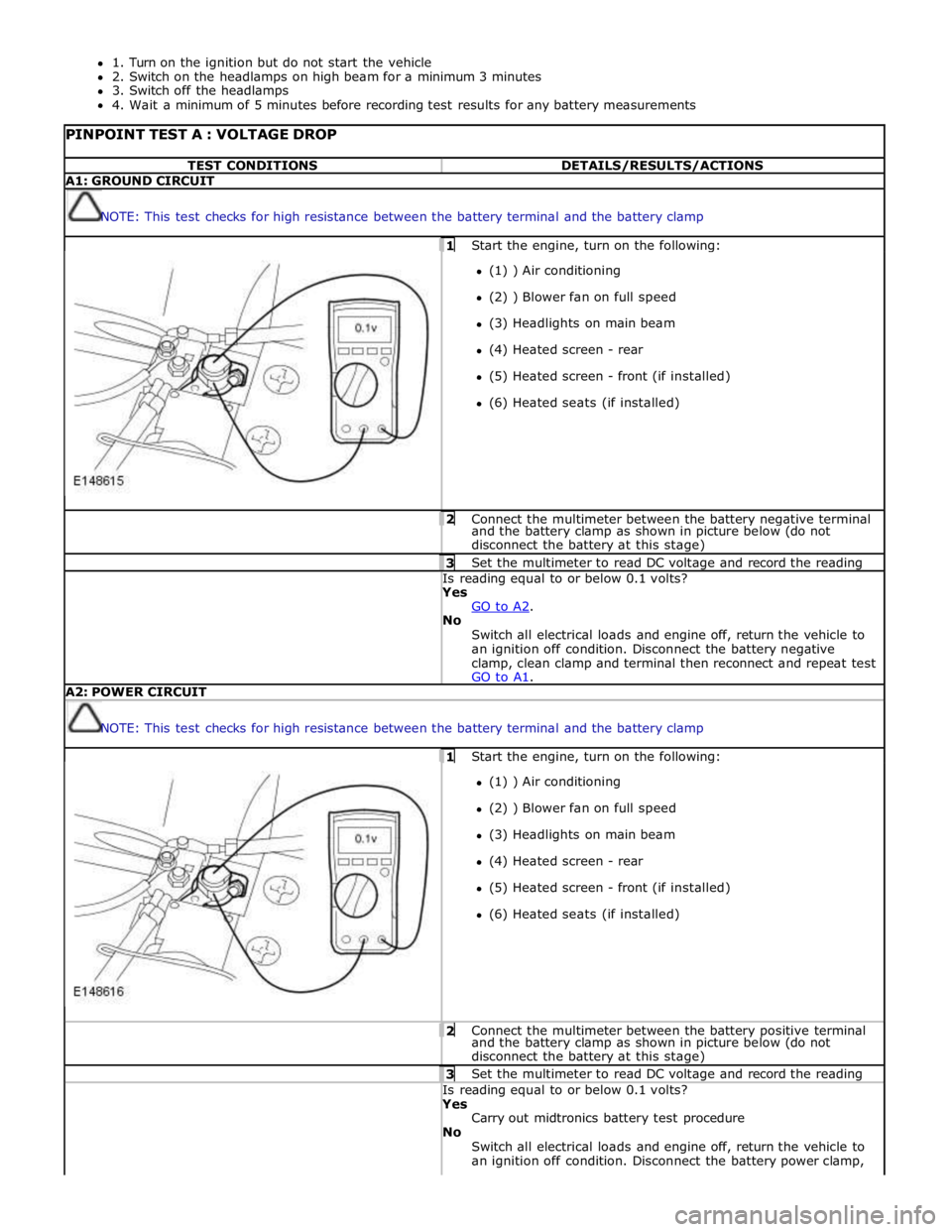
PINPOINT TEST A : VOLTAGE DROP TEST CONDITIONS DETAILS/RESULTS/ACTIONS A1: GROUND CIRCUIT
NOTE: This test checks for high resistance between the battery terminal and the battery clamp 1 Start the engine, turn on the following: (1) ) Air conditioning
(2) ) Blower fan on full speed
(3) Headlights on main beam
(4) Heated screen - rear
(5) Heated screen - front (if installed)
(6) Heated seats (if installed) 2 Connect the multimeter between the battery negative terminal and the battery clamp as shown in picture below (do not
disconnect the battery at this stage) 3 Set the multimeter to read DC voltage and record the reading Is reading equal to or below 0.1 volts? Yes
GO to A2. No
Switch all electrical loads and engine off, return the vehicle to
an ignition off condition. Disconnect the battery negative
clamp, clean clamp and terminal then reconnect and repeat test
GO to A1. A2: POWER CIRCUIT
NOTE: This test checks for high resistance between the battery terminal and the battery clamp 1 Start the engine, turn on the following: (1) ) Air conditioning
(2) ) Blower fan on full speed
(3) Headlights on main beam
(4) Heated screen - rear
(5) Heated screen - front (if installed)
(6) Heated seats (if installed) 2 Connect the multimeter between the battery positive terminal and the battery clamp as shown in picture below (do not
disconnect the battery at this stage) 3 Set the multimeter to read DC voltage and record the reading Is reading equal to or below 0.1 volts? Yes
Carry out midtronics battery test procedure
No
Switch all electrical loads and engine off, return the vehicle to
an ignition off condition. Disconnect the battery power clamp,
Page 1910 of 3039

Published: 11-May-2011
Generator and Regulator - V8 5.0L Petrol/V8 S/C 5.0L Petrol - Generator - Overview
Description and Operation
OVERVIEW
On 5.0L V8 vehicles (naturally aspirated and supercharger), the charging system consists of a 150 Amp output generator and
regulator assembly. The generator and regulator assembly generates electrical power for the vehicle electrical system and
maintains the battery in a charged state.
When the engine is running the generator produces an alternating current, which is converted to a direct current internally. The
output from the generator is controlled by the voltage regulator (located inside the generator) and then supplied to the battery
through the main battery positive cable. The generator is mounted on the front right side of the engine and driven at
approximately 3 times engine speed by the accessory drive belt.
Page 1912 of 3039

transmits the calculated voltage to the generator and regulator on the LIN bus connection.
The ECM will over-ride the voltage value requested by the battery monitoring system if it detects a fault in the generator and regulator. The ECM also signals the instrument cluster to display a warning message if it detects a fault with the generator and regulator. For additionalinformation refer to Instrument Cluster 413-01.
GENERATOR AND REGULATOR Component Description
The regulator provides a controlled variable voltage output from the generator. Two electrical terminals are provided on the
outer casing of the generator. One terminal supplies the DC (direct current) voltage output from the generator to the battery
positive terminal. The second terminal provides the LIN bus connection between the regulator and the ECM. www.JagDocs.com
Page 1932 of 3039
Published: 11-Jul-2014
Information and Entertainment System - General Information - Information
and Entertainment System
Diagnosis and Testing
Principle of Operation
For a detailed description of the Information and Entertainment System, refer to the relevant Description and Operation
sections in the workshop manual. REFER to: (415-01A Information and Entertainment System)
Audio System (Description and Operation), Audio System (Description and Operation), Audio System (Description and Operation).
Inspection and Verification
CAUTION: Diagnosis by substitution from a donor vehicle is NOT acceptable. Substitution of control modules does not
guarantee confirmation of a fault, and may also cause additional faults in the vehicle being tested and/or the donor vehicle.
1. Verify the customer concern.
2. Visually inspect for obvious signs of damage and system integrity.
Visual Inspection
Mechanical Electrical
Information and entertainment module
Audio amplifier module
Integrated audio module
Portable audio interface module
Digital audio broadcast module
Integrated control panel
Touch screen display
Satellite radio module
Television module
Navigation system module
Telephone module
Compact disc player jammed, not loading
Scratched/dirty compact discs
Speakers
Fuses
Loose or corroded connector(s)
Information and entertainment module
Audio amplifier module
Integrated audio module
Portable audio interface module
Digital audio broadcast module
Integrated control panel
Touch screen display
Satellite radio module
Television module
Navigation system module
Telephone module
Speakers
3. If an obvious cause for an observed or reported concern is found, correct the cause (if possible) before proceeding to
the next step.
4. If the cause is not visually evident, check for Diagnostic Trouble Codes (DTCs) and refer to the relevant DTC Index.
Symptom Chart
Symptom Display Possible Causes Action Poor audio quality (all
sources) Display normal
MOST harness
connections loose
MOST harness
connections
contaminated
MOST harness
misrouted
- Too many
bends
- Bend radius
less than
25mm
Check MOST harness connectors for
security
Check MOST harness connectors for
contamination
Check the routing of the MOST harness Information and
entertainment system
inoperative Touch screen blank or
displaying a flashing
logo
MOST network fault
REFER to: Communications Network (418-00 Module Communications Network,
Diagnosis and Testing).
DTC Index
For a list of Diagnostic Trouble Codes (DTCs) that could be logged on this vehicle, please refer to Section 100-00. REFER to:
(100-00 General Information)
Page 1934 of 3039
Published: 11-May-2011
Information and Entertainment System - General Information - Cellular
Phone
Diagnosis and Testing
Principle of Operation
For a detailed description of the Cellular Phone System, refer to the relevant Description and Operation sections in the
workshop manual.
Inspection and Verification
CAUTION: Diagnosis by substitution from a donor vehicle is NOT acceptable. Substitution of control modules does not
guarantee confirmation of a fault, and may also cause additional faults in the vehicle being tested and/or the donor vehicle.
1. Verify the customer concern.
2. Visually inspect for obvious signs of damage and system integrity.
Visual Inspection
Mechanical Electrical
Microphone
Bluetooth antenna
Electrical connectors
Wiring harness for damage or corrosion
Fuses
3. If an obvious cause for an observed or reported concern is found, correct the cause (if possible) before proceeding to
the next step.
4. If the cause is not visually evident, verify the symptom and refer to the Symptom Chart, alternatively check for
Diagnostic Trouble Codes (DTCs) and refer to the relevant DTC Index.
Symptom Chart
Symptom Action Unable to pair
GO to Pinpoint Test A. Not Auto Connecting
GO to Pinpoint Test B. No Audio to 3rd Party
GO to Pinpoint Test C. No Audio from 3rd Party
GO to Pinpoint Test D. No Audio
GO to Pinpoint Test E. DTC Index
CAUTION: When probing connectors to take measurements in the course of the pinpoint tests, use the adaptor kit, part
number 3548-1358-00
NOTES:
If the control module or a component is suspect and the vehicle remains under manufacturer warranty, refer to the
Warranty Policy and Procedures manual (section B1.2), or determine if any prior approval programme is in operation, prior to
the installation of a new module/component.
Generic scan tools may not read the codes listed, or may read only five digit codes. Match the five digits from the scan
tool to the first five digits of the seven digit code listed to identify the fault (the last two digits give extra information read by
the manufacturer-approved diagnostic system).
When performing voltage or resistance tests, always use a digital multimeter (DMM) accurate to three decimal places and
with a current calibration certificate. When testing resistance, always take the resistance of the DMM leads into account.
Page 1935 of 3039
Check and rectify basic faults before beginning diagnostic routines involving pinpoint tests.
If DTCs are recorded and, after performing the pinpoint tests, a fault is not present, an intermittent concern may be the
cause. Always check for loose connections and corroded terminals.
DTC Description Possible Cause Action B1A5613 Antenna
Bluetooth antenna circuit -
open circuit Refer to the electrical circuit diagrams and check blue tooth
antenna circuit for open circuit B1D7984 Microphone Input
Signal amplitude <
minimum Refer to the electrical circuit diagrams and test microphone
input circuit for short/open circuit. Check integrated audio
module for related DTCs and refer to relevant DTC Index U1A0088
Private
Communication
Network
Bluetooth phone module
internal communications
failure Suspect the module. Check and install a new telephone
module as required, refer to the new module/component
installation note at the top of the DTC Index U210000
Initial
Configuration Not
Complete
Initial configuration not
complete Re-configure the RJB using the manufacturer approved
diagnostic system. If DTC remains, carry out CAN network
integrity tests using the manufacturer approved diagnostic system U210100
Control Module
Configuration
Incompatible
Configuration incompatible Re-configure the RJB using the manufacturer approved
diagnostic system. If DTC remains, suspect the telephone
module. Check and install a new telephone module as
required, refer to the new module/component installation note
at the top of the DTC Index U300044 Control Module
Data memory failure Re-configure the telephone module. If the DTC remains,
suspect the telephone module. Check and install a new
telephone module as required, refer to the new
module/component installation note at the top of the DTC
Index U300045 Control Module
Program memory failure Re-configure the telephone module. If the DTC remains,
suspect the telephone module. Check and install a new
telephone module as required, refer to the new
module/component installation note at the top of the DTC
Index U300055 Control Module
Incorrect car configuration
data received Re-configure the RJB using the manufacturer approved
diagnostic system. Clear DTC and re-test. If the DTC remains
suspect the telephone module. Check and install a new
module as required, refer to the new module/component
installation note at the top of the DTC Index U300098 Control Module
Component or system over
temperature Check for additional DTCs and refer to DTC Index. Clear DTC
and re-test/monitor condition for re-occurrence U300362 Battery Voltage
Mis-match in battery
voltage, of 2 volts or more,
between telephone module
and RJB Carry out any pinpoint tests associated with this DTC using
the manufacturer approved diagnostic system
Pinpoint Tests
PINPOINT TEST A : UNABLE TO PAIR TEST
CONDITIONS DETAILS/RESULTS/ACTIONS A1: 'NO PHONE FITTED' DISPLAY
NOTE: Prior to continuing with any diagnosis, ensure that the Customer telephone and level of software is included on
the JLR approved list, the telephone battery is fully charged and in a serviceable condition, the bluetooth function is activated
and the telephone handset is placed within the vehicle cabin area. 1 Carry out checks to determine if 'No Phone Fitted' is shown on vehicle display. Is 'No Phone Fitted' displayed? Yes
GO to A2. No
Locate the connected telephone and if not Customer telephone, disconnect from the system. A2: TELEPHONE BLUETOOTH DEVICE SEARCH 1 Carry out Bluetooth device search using Customer handset. www.JagDocs.com
Page 1937 of 3039
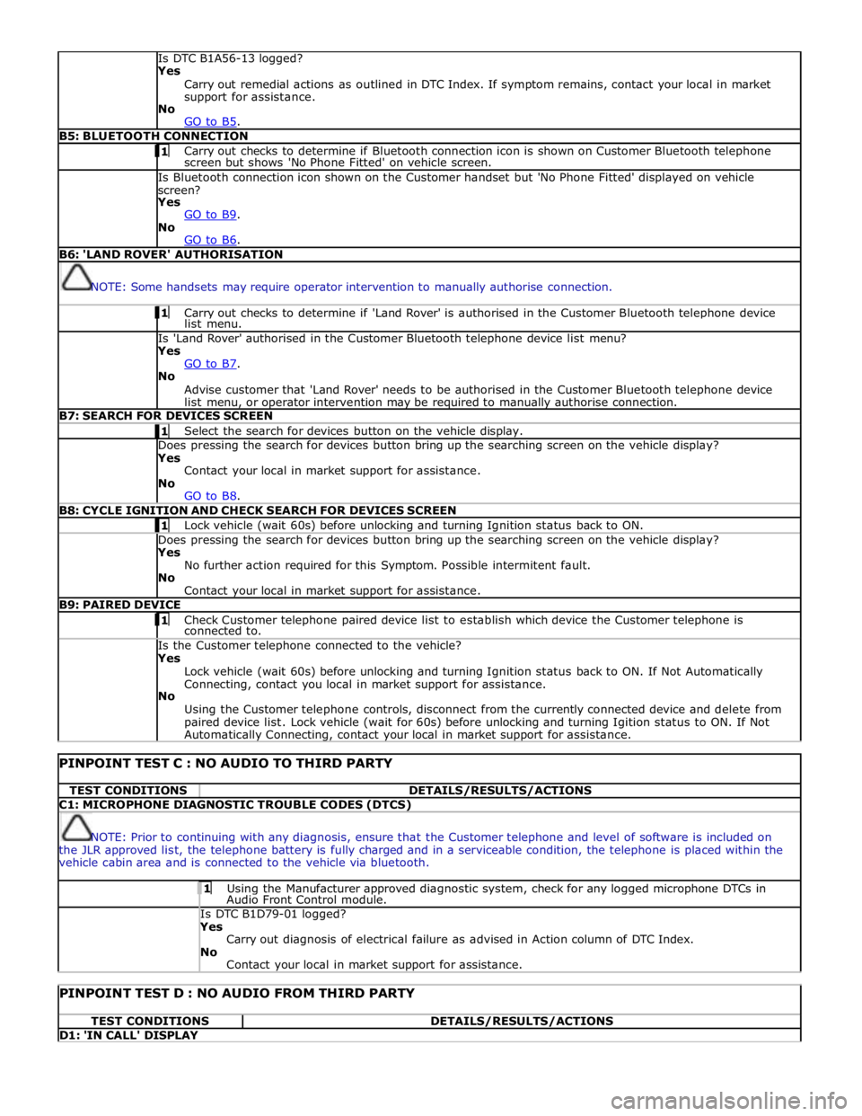
Is DTC B1A56-13 logged?
Yes
Carry out remedial actions as outlined in DTC Index. If symptom remains, contact your local in market
support for assistance.
No
GO to B5. B5: BLUETOOTH CONNECTION 1 Carry out checks to determine if Bluetooth connection icon is shown on Customer Bluetooth telephone screen but shows 'No Phone Fitted' on vehicle screen. Is Bluetooth connection icon shown on the Customer handset but 'No Phone Fitted' displayed on vehicle
screen?
Yes
GO to B9. No
GO to B6. B6: 'LAND ROVER' AUTHORISATION
NOTE: Some handsets may require operator intervention to manually authorise connection. 1 Carry out checks to determine if 'Land Rover' is authorised in the Customer Bluetooth telephone device list menu. Is 'Land Rover' authorised in the Customer Bluetooth telephone device list menu?
Yes
GO to B7. No
Advise customer that 'Land Rover' needs to be authorised in the Customer Bluetooth telephone device
list menu, or operator intervention may be required to manually authorise connection. B7: SEARCH FOR DEVICES SCREEN 1 Select the search for devices button on the vehicle display. Does pressing the search for devices button bring up the searching screen on the vehicle display?
Yes
Contact your local in market support for assistance.
No
GO to B8. B8: CYCLE IGNITION AND CHECK SEARCH FOR DEVICES SCREEN 1 Lock vehicle (wait 60s) before unlocking and turning Ignition status back to ON. Does pressing the search for devices button bring up the searching screen on the vehicle display?
Yes
No further action required for this Symptom. Possible intermitent fault.
No
Contact your local in market support for assistance. B9: PAIRED DEVICE 1 Check Customer telephone paired device list to establish which device the Customer telephone is connected to. Is the Customer telephone connected to the vehicle?
Yes
Lock vehicle (wait 60s) before unlocking and turning Ignition status back to ON. If Not Automatically
Connecting, contact you local in market support for assistance.
No
Using the Customer telephone controls, disconnect from the currently connected device and delete from
paired device list. Lock vehicle (wait for 60s) before unlocking and turning Igition status to ON. If Not Automatically Connecting, contact your local in market support for assistance.
PINPOINT TEST C : NO AUDIO TO THIRD PARTY TEST CONDITIONS DETAILS/RESULTS/ACTIONS C1: MICROPHONE DIAGNOSTIC TROUBLE CODES (DTCS)
NOTE: Prior to continuing with any diagnosis, ensure that the Customer telephone and level of software is included on
the JLR approved list, the telephone battery is fully charged and in a serviceable condition, the telephone is placed within the
vehicle cabin area and is connected to the vehicle via bluetooth. 1 Using the Manufacturer approved diagnostic system, check for any logged microphone DTCs in Audio Front Control module. Is DTC B1D79-01 logged? Yes
Carry out diagnosis of electrical failure as advised in Action column of DTC Index.
No
Contact your local in market support for assistance.
PINPOINT TEST D : NO AUDIO FROM THIRD PARTY TEST CONDITIONS DETAILS/RESULTS/ACTIONS D1: 'IN CALL' DISPLAY
Page 1938 of 3039
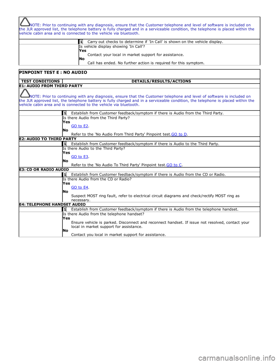
NOTE: Prior to continuing with any diagnosis, ensure that the Customer telephone and level of software is included on
the JLR approved list, the telephone battery is fully charged and in a serviceable condition, the telephone is placed within the
vehicle cabin area and is connected to the vehicle via bluetooth. 1 Carry out checks to determine if 'In Call' is shown on the vehicle display. Is vehicle display showing 'In Call'?
Yes
Contact your local in market support for assistance.
No
Call has ended. No further action is required for this symptom.
PINPOINT TEST E : NO AUDIO TEST CONDITIONS DETAILS/RESULTS/ACTIONS E1: AUDIO FROM THIRD PARTY
NOTE: Prior to continuing with any diagnosis, ensure that the Customer telephone and level of software is included on
the JLR approved list, the telephone battery is fully charged and in a serviceable condition, the telephone is placed within the
vehicle cabin area and is connected to the vehicle via bluetooth. 1 Establish from Customer feedback/symptom if there is Audio from the Third Party. Is there Audio from the Third Party? Yes
GO to E2. No
Refer to the 'No Audio From Third Party' Pinpoint test.GO to D. E2: AUDIO TO THIRD PARTY 1 Establish from Customer feedback/symptom if there is Audio to the Third Party. Is there Audio to the Third Party? Yes
GO to E3. No
Refer to the 'No Audio To Third Party' Pinpoint test.GO to C. E3: CD OR RADIO AUDIO 1 Establish from Customer feedback/symptom if there is Audio from the CD or Radio. Is there Audio from the CD or Radio? Yes
GO to E4. No
Suspect MOST ring fault, refer to electrical circuit diagrams and check/rectify MOST ring as necessary. E4: TELEPHONE HANDSET AUDIO 1 Establish from Customer feedback/symptom if there is Audio from the telephone handset. Is there Audio from the telephone handset? Yes
Ensure vehicle is parked. Disconnect and reconnect handset. If issue not resolved, contact your
local in market support for assistance.
No
Contact you local in market support for assistance.