2010 JAGUAR XFR coolant temperature
[x] Cancel search: coolant temperaturePage 1387 of 3039
Published: 19-Aug-2013
Electronic Engine Controls - V8 S/C 5.0L Petrol - Engine Coolant Temperature
(ECT) Sensor
Removal and Installation
Removal
NOTES:
Some variation in the illustrations may occur, but the essential information is always correct.
Removal steps in this procedure may contain installation details.
1. WARNING: Do not work on or under a vehicle supported only by a jack.
Always support the vehicle on safety stands.
Raise and support the vehicle.
2. Refer to: Cooling System Partial Draining, Filling and Bleeding (303-03B Engine Cooling - V6 3.0L Petrol, General Procedures).
3. Refer to: Catalytic Converter RH (309-00C Exhaust System - V8 5.0L Petrol/V8 S/C 5.0L Petrol, Removal and Installation).
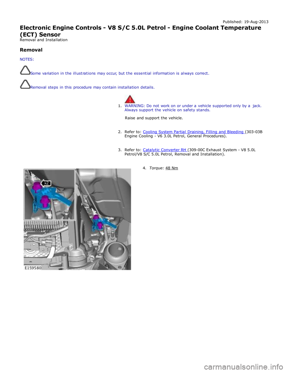
4. Torque: 48 Nm
Page 1388 of 3039
Installation 5. WARNING: Fluid loss is unavoidable, use absorbent
cloth or a container to collect the fluid.
CAUTION: Engine coolant will damage the paint
finished surfaces. If spilt, immediately remove the coolant
and clean the area with water.
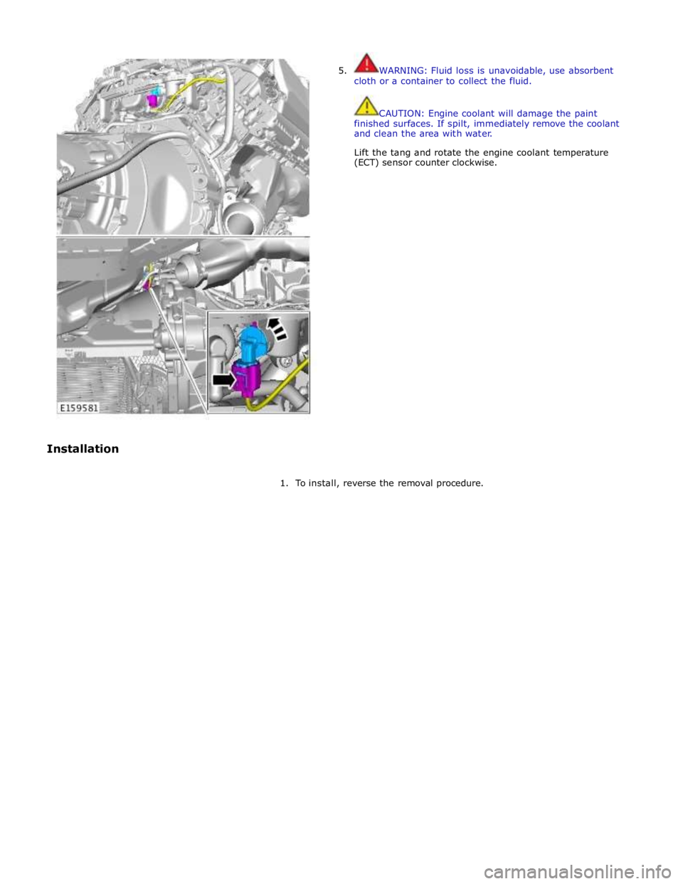
Lift the tang and rotate the engine coolant temperature
(ECT) sensor counter clockwise.
1. To install, reverse the removal procedure.
Page 1487 of 3039
30. CAUTION: Observe the engine temperature warning light. If the
warning light is displayed, switch off immediately and allow to cool.
Failure to follow this instruction may cause damage to the vehicle.
Raise the engine speed to 2000 RPM and maintain at 2000 RPM until the
engine cooling fan operates.
31. CAUTION: Switch off the engine and allow the coolant temperature
to go cold.
Switch the engine off and allow to cool.
32. Visually check the engine and cooling system for signs of coolant
leakage.
33. WARNINGS:
When releasing the cooling system pressure, cover the coolant
expansion tank cap with a thick cloth.
Since injury such as scalding could be caused by escaping steam or
coolant, make sure the vehicle cooling system is cool prior to carrying
out this procedure.
CAUTIONS:
Make sure the coolant level remains above the "COLD FILL RANGE"
lower level mark.
Anti-freeze concentration must be maintained at 50%.
NOTE: When the cooling system is warm, the coolant will be
approximately 10mm above the upper level mark on the expansion tank
with the cap removed.
Check and top-up the coolant if required.
34. Refer to: Transmission Fluid Level Check (307-01B Automatic Transmission/Transaxle - TDV6 3.0L Diesel /V8 5.0L Petrol/V8 S/C 5.0L
Petrol, General Procedures).
Page 1503 of 3039
28. CAUTION: Observe the engine temperature warning light. If the
warning light is displayed, switch off immediately and allow to cool.
Failure to follow this instruction may cause damage to the vehicle.
Raise the engine speed to 2000 RPM and maintain at 2000 RPM until the
engine cooling fan operates.
29. CAUTION: Switch off the engine and allow the coolant temperature
to go cold.
Switch the engine off and allow to cool.
30. Visually check the engine and cooling system for signs of coolant
leakage.
31. WARNINGS:
When releasing the cooling system pressure, cover the coolant
expansion tank cap with a thick cloth.
Since injury such as scalding could be caused by escaping steam or
coolant, make sure the vehicle cooling system is cool prior to carrying
out this procedure.
CAUTIONS:
Make sure the coolant level remains above the "COLD FILL RANGE"
lower level mark.
Anti-freeze concentration must be maintained at 50%.
NOTE: When the cooling system is warm, the coolant will be
approximately 10mm above the upper level mark on the expansion tank
with the cap removed.
Check and top-up the coolant if required.
32. Refer to: Transmission Fluid Level Check (307-01B Automatic Transmission/Transaxle - TDV6 3.0L Diesel /V8 5.0L Petrol/V8 S/C 5.0L
Petrol, General Procedures).
Page 1596 of 3039
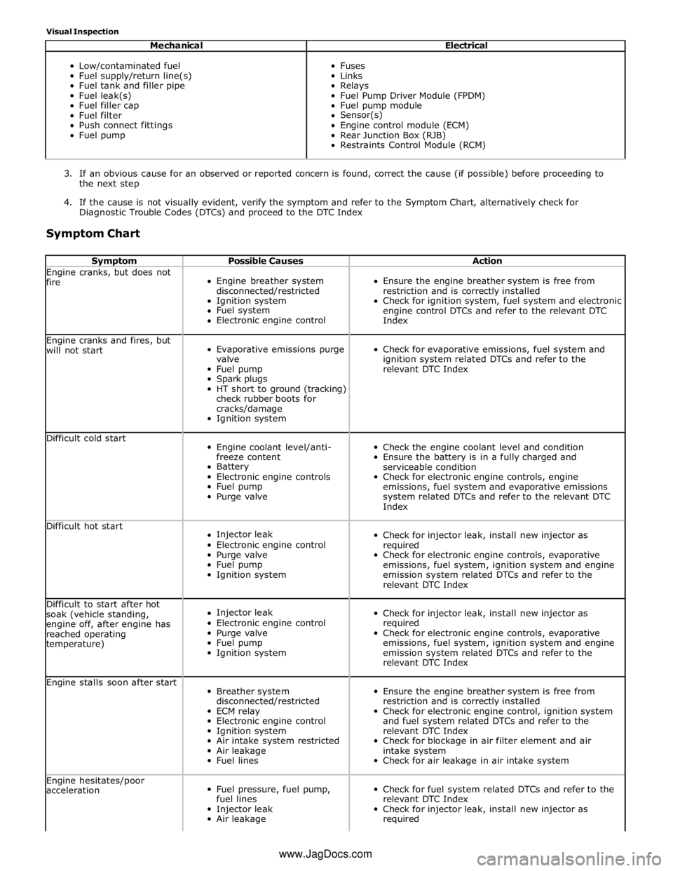
Visual Inspection
Mechanical Electrical
Low/contaminated fuel
Fuel supply/return line(s)
Fuel tank and filler pipe
Fuel leak(s)
Fuel filler cap
Fuel filter
Push connect fittings
Fuel pump
Fuses
Links
Relays
Fuel Pump Driver Module (FPDM)
Fuel pump module
Sensor(s)
Engine control module (ECM)
Rear Junction Box (RJB)
Restraints Control Module (RCM)
3. If an obvious cause for an observed or reported concern is found, correct the cause (if possible) before proceeding to
the next step
4. If the cause is not visually evident, verify the symptom and refer to the Symptom Chart, alternatively check for
Diagnostic Trouble Codes (DTCs) and proceed to the DTC Index
Symptom Chart
Symptom Possible Causes Action Engine cranks, but does not
fire
Engine breather system
disconnected/restricted
Ignition system
Fuel system
Electronic engine control
Ensure the engine breather system is free from
restriction and is correctly installed
Check for ignition system, fuel system and electronic
engine control DTCs and refer to the relevant DTC
Index Engine cranks and fires, but
will not start
Evaporative emissions purge
valve
Fuel pump
Spark plugs
HT short to ground (tracking)
check rubber boots for
cracks/damage
Ignition system
Check for evaporative emissions, fuel system and
ignition system related DTCs and refer to the
relevant DTC Index Difficult cold start
Engine coolant level/anti-
freeze content
Battery
Electronic engine controls
Fuel pump
Purge valve
Check the engine coolant level and condition
Ensure the battery is in a fully charged and
serviceable condition
Check for electronic engine controls, engine
emissions, fuel system and evaporative emissions
system related DTCs and refer to the relevant DTC
Index Difficult hot start
Injector leak
Electronic engine control
Purge valve
Fuel pump
Ignition system
Check for injector leak, install new injector as
required
Check for electronic engine controls, evaporative
emissions, fuel system, ignition system and engine
emission system related DTCs and refer to the
relevant DTC Index Difficult to start after hot
soak (vehicle standing,
engine off, after engine has
reached operating
temperature)
Injector leak
Electronic engine control
Purge valve
Fuel pump
Ignition system
Check for injector leak, install new injector as
required
Check for electronic engine controls, evaporative
emissions, fuel system, ignition system and engine
emission system related DTCs and refer to the
relevant DTC Index Engine stalls soon after start
Breather system
disconnected/restricted
ECM relay
Electronic engine control
Ignition system
Air intake system restricted
Air leakage
Fuel lines
Ensure the engine breather system is free from
restriction and is correctly installed
Check for electronic engine control, ignition system
and fuel system related DTCs and refer to the
relevant DTC Index
Check for blockage in air filter element and air
intake system
Check for air leakage in air intake system Engine hesitates/poor
acceleration
Fuel pressure, fuel pump,
fuel lines
Injector leak
Air leakage
Check for fuel system related DTCs and refer to the
relevant DTC Index
Check for injector leak, install new injector as
required www.JagDocs.com
Page 1664 of 3039
Published: 11-Jul-2014
Climate Control System - General Information - Climate Control System
Diagnosis and Testing
Principles of Operation
For a detailed description of the Climate Control System, refer to the relevant Description and Operation sections in the
Workshop Manual. REFER to:
Air Distribution and Filtering (412-01 Climate Control, Description and Operation), Air Distribution and Filtering (412-01 Climate Control, Description and Operation), Air Distribution and Filtering (412-01 Climate Control, Description and Operation), Heating and Ventilation (412-01 Climate Control, Description and Operation), Heating and Ventilation (412-01 Climate Control, Description and Operation), Heating and Ventilation (412-01 Climate Control, Description and Operation), Air Conditioning (412-01 Climate Control, Description and Operation), Air Conditioning (412-01 Climate Control, Description and Operation), Air Conditioning (412-01 Climate Control, Description and Operation), Control Components (412-01 Climate Control, Description and Operation), Control Components (412-01 Climate Control, Description and Operation), Control Components (412-01 Climate Control, Description and Operation), Electric Booster Heater (412-02 Auxiliary Climate Control, Description and Operation), Electric Booster Heater (412-02 Auxiliary Climate Control, Description and Operation), Electric Booster Heater (412-02 Auxiliary Climate Control, Description and Operation).
Inspection and Verification
WARNING: Servicing must be carried out by personnel familiar with both vehicle system and the charging and testing
equipment. All operations must be carried out in a well ventilated area away from open flame and heat sources.
CAUTION: Diagnosis by substitution from a donor vehicle is NOT acceptable. Substitution of control modules does not
guarantee confirmation of a fault, and may also cause additional faults in the vehicle being tested and/or the donor vehicle.
NOTE: Check and rectify basic faults before beginning diagnostic routines involving pinpoint tests.
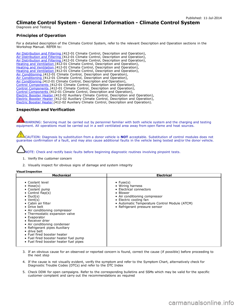
1. Verify the customer concern
2. Visually inspect for obvious signs of damage and system integrity
Visual Inspection
Mechanical Electrical
Coolant level
Hose(s)
Coolant pump
Control flap(s)
Duct(s)
Vent(s)
Cabin air filter
Drive belt
Air conditioning compressor
Thermostatic expansion valve
Evaporator
Receiver drier
Air conditioning condenser
Refrigerant pipes Auxiliary
drive belt
Fuel fired booster heater
Fuel fired booster heater fuel pump
Fuel fired booster heater fuel pipes
Fuse(s)
Wiring harness
Electrical connectors
Blower
Air conditioning compressor
Electric cooling fan
Automatic Temperature Control Module (ATCM)
Refrigerant pressure sensor
3. If an obvious cause for an observed or reported concern is found, correct the cause (if possible) before proceeding to
the next step
4. If the cause is not visually evident, verify the symptom and refer to the Symptom Chart, alternatively check for
Diagnostic Trouble Codes (DTCs) and refer to the DTC Index
5. Check DDW for open campaigns. Refer to the corresponding bulletins and SSMs which may be valid for the specific
customer complaint and carry out the recommendations as required
Page 1690 of 3039
Published: 11-May-2011
Climate Control - Heating and Ventilation - Component Location
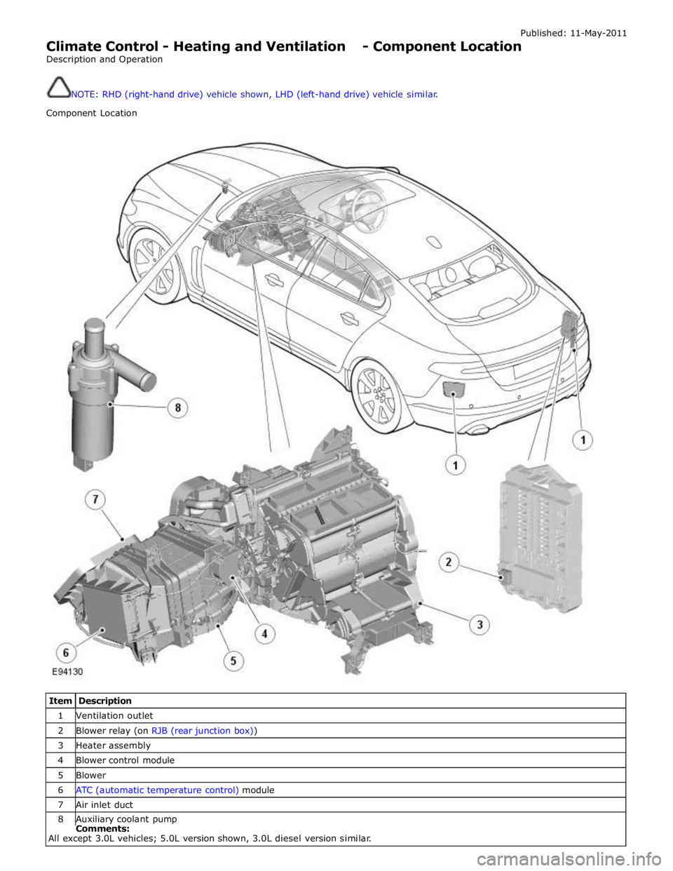
Description and Operation
NOTE: RHD (right-hand drive) vehicle shown, LHD (left-hand drive) vehicle similar.
Component Location
Item Description 1 Ventilation outlet 2 Blower relay (on RJB (rear junction box)) 3 Heater assembly 4 Blower control module 5 Blower 6 ATC (automatic temperature control) module 7 Air inlet duct 8 Auxiliary coolant pump Comments:
All except 3.0L vehicles; 5.0L version shown, 3.0L diesel version similar.
Page 1693 of 3039
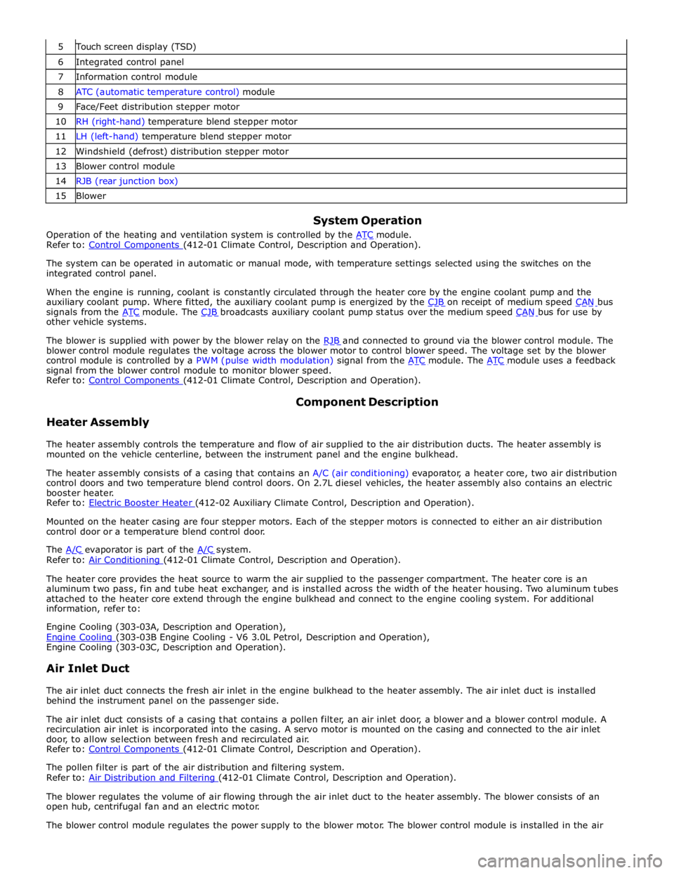
Touch screen display (TSD) 6 Integrated control panel 7 Information control module 8 ATC (automatic temperature control) module 9 Face/Feet distribution stepper motor 10 RH (right-hand) temperature blend stepper motor 11 LH (left-hand) temperature blend stepper motor 12 Windshield (defrost) distribution stepper motor 13 Blower control module 14 RJB (rear junction box) 15 Blower
System Operation
Operation of the heating and ventilation system is controlled by the ATC module. Refer to: Control Components (412-01 Climate Control, Description and Operation).
The system can be operated in automatic or manual mode, with temperature settings selected using the switches on the
integrated control panel.
When the engine is running, coolant is constantly circulated through the heater core by the engine coolant pump and the
auxiliary coolant pump. Where fitted, the auxiliary coolant pump is energized by the CJB on receipt of medium speed CAN bus signals from the ATC module. The CJB broadcasts auxiliary coolant pump status over the medium speed CAN bus for use by other vehicle systems.
The blower is supplied with power by the blower relay on the RJB and connected to ground via the blower control module. The blower control module regulates the voltage across the blower motor to control blower speed. The voltage set by the blower
control module is controlled by a PWM (pulse width modulation) signal from the ATC module. The ATC module uses a feedback signal from the blower control module to monitor blower speed.
Refer to: Control Components (412-01 Climate Control, Description and Operation).
Heater Assembly Component Description
The heater assembly controls the temperature and flow of air supplied to the air distribution ducts. The heater assembly is
mounted on the vehicle centerline, between the instrument panel and the engine bulkhead.
The heater assembly consists of a casing that contains an A/C (air conditioning) evaporator, a heater core, two air distribution
control doors and two temperature blend control doors. On 2.7L diesel vehicles, the heater assembly also contains an electric
booster heater.
Refer to: Electric Booster Heater (412-02 Auxiliary Climate Control, Description and Operation).
Mounted on the heater casing are four stepper motors. Each of the stepper motors is connected to either an air distribution
control door or a temperature blend control door.
The A/C evaporator is part of the A/C system. Refer to: Air Conditioning (412-01 Climate Control, Description and Operation).
The heater core provides the heat source to warm the air supplied to the passenger compartment. The heater core is an
aluminum two pass, fin and tube heat exchanger, and is installed across the width of the heater housing. Two aluminum tubes
attached to the heater core extend through the engine bulkhead and connect to the engine cooling system. For additional
information, refer to:
Engine Cooling (303-03A, Description and Operation),
Engine Cooling (303-03B Engine Cooling - V6 3.0L Petrol, Description and Operation), Engine Cooling (303-03C, Description and Operation).
Air Inlet Duct
The air inlet duct connects the fresh air inlet in the engine bulkhead to the heater assembly. The air inlet duct is installed
behind the instrument panel on the passenger side.
The air inlet duct consists of a casing that contains a pollen filter, an air inlet door, a blower and a blower control module. A
recirculation air inlet is incorporated into the casing. A servo motor is mounted on the casing and connected to the air inlet
door, to allow selection between fresh and recirculated air.
Refer to: Control Components (412-01 Climate Control, Description and Operation). The pollen filter is part of the air distribution and filtering system.
Refer to: Air Distribution and Filtering (412-01 Climate Control, Description and Operation).
The blower regulates the volume of air flowing through the air inlet duct to the heater assembly. The blower consists of an
open hub, centrifugal fan and an electric motor.
The blower control module regulates the power supply to the blower motor. The blower control module is installed in the air