2010 JAGUAR XFR coolant temperature
[x] Cancel search: coolant temperaturePage 1767 of 3039

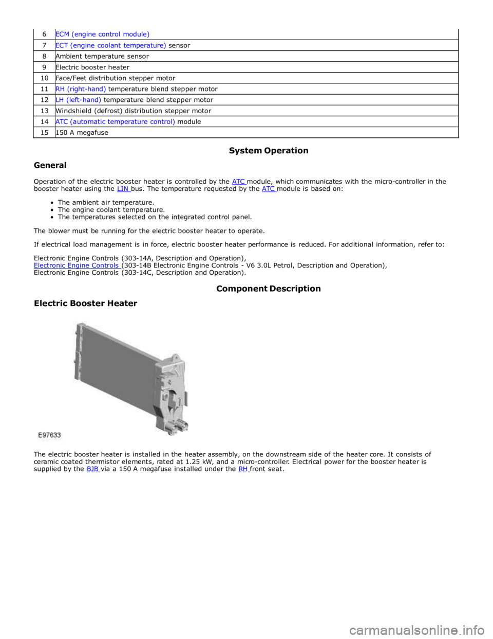
7 ECT (engine coolant temperature) sensor 8 Ambient temperature sensor 9 Electric booster heater 10 Face/Feet distribution stepper motor 11 RH (right-hand) temperature blend stepper motor 12 LH (left-hand) temperature blend stepper motor 13 Windshield (defrost) distribution stepper motor 14 ATC (automatic temperature control) module 15 150 A megafuse
General System Operation
Operation of the electric booster heater is controlled by the ATC module, which communicates with the micro-controller in the booster heater using the LIN bus. The temperature requested by the ATC module is based on:
The ambient air temperature.
The engine coolant temperature.
The temperatures selected on the integrated control panel.
The blower must be running for the electric booster heater to operate.
If electrical load management is in force, electric booster heater performance is reduced. For additional information, refer to:
Electronic Engine Controls (303-14A, Description and Operation),
Electronic Engine Controls (303-14B Electronic Engine Controls - V6 3.0L Petrol, Description and Operation), Electronic Engine Controls (303-14C, Description and Operation).
Electric Booster Heater Component Description
The electric booster heater is installed in the heater assembly, on the downstream side of the heater core. It consists of
ceramic coated thermistor elements, rated at 1.25 kW, and a micro-controller. Electrical power for the booster heater is
supplied by the BJB via a 150 A megafuse installed under the RH front seat.
Page 1770 of 3039

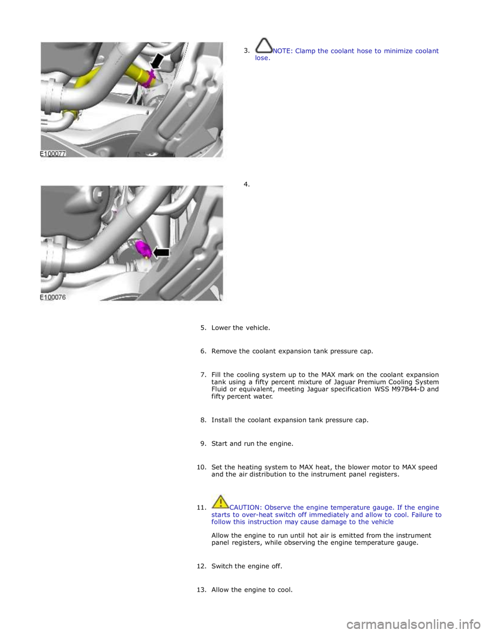
3.
lose.
4. NOTE: Clamp the coolant hose to minimize coolant
5. Lower the vehicle.
6. Remove the coolant expansion tank pressure cap.
7. Fill the cooling system up to the MAX mark on the coolant expansion
tank using a fifty percent mixture of Jaguar Premium Cooling System
Fluid or equivalent, meeting Jaguar specification WSS M97B44-D and
fifty percent water.
8. Install the coolant expansion tank pressure cap.
9. Start and run the engine.
10. Set the heating system to MAX heat, the blower motor to MAX speed
and the air distribution to the instrument panel registers.
11. CAUTION: Observe the engine temperature gauge. If the engine
starts to over-heat switch off immediately and allow to cool. Failure to
follow this instruction may cause damage to the vehicle
Allow the engine to run until hot air is emitted from the instrument
panel registers, while observing the engine temperature gauge.
12. Switch the engine off.
13. Allow the engine to cool.
Page 1788 of 3039

gage, odometer, trip distance and trip computer readouts. The trip distance and trip computer information is derived from
information supplied on the high speed CAN bus to the instrument cluster from the ABS module and the ECM.
The area above the message center displays the transmission gear position information and speed control related information.
The transmission information is supplied on the high speed CAN bus from the TCM (transmission control module).
NOTE: There is no engine coolant temperature gage displayed. If the engine coolant temperature increases to above a
predetermined threshold, a warning message is displayed in the message center. The message is sent from the ECM in a high speed CAN message to the instrument cluster.
TRANSMISSION GEAR SELECTION POSITION
The gear position display shows JaguarDrive selector position or selected gear when using the Jaguar Sequential Shift. The gear
selector module transmits a CAN message to the instrument cluster for gear selector lever position. The module also outputs a 'not in park' signal to the instrument cluster. The TCM transmits a high speed CAN message to the instrument cluster with data containing the selected gear when in Jaguar Sequential Shift mode.
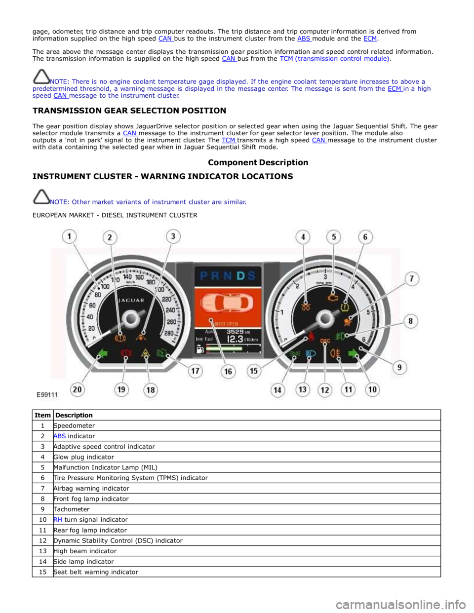
Component Description INSTRUMENT CLUSTER - WARNING INDICATOR LOCATIONS
NOTE: Other market variants of instrument cluster are similar.
EUROPEAN MARKET - DIESEL INSTRUMENT CLUSTER
Item Description 1 Speedometer 2 ABS indicator 3 Adaptive speed control indicator 4 Glow plug indicator 5 Malfunction Indicator Lamp (MIL) 6 Tire Pressure Monitoring System (TPMS) indicator 7 Airbag warning indicator 8 Front fog lamp indicator 9 Tachometer 10 RH turn signal indicator 11 Rear fog lamp indicator 12 Dynamic Stability Control (DSC) indicator 13 High beam indicator 14 Side lamp indicator 15 Seat belt warning indicator
Page 1825 of 3039

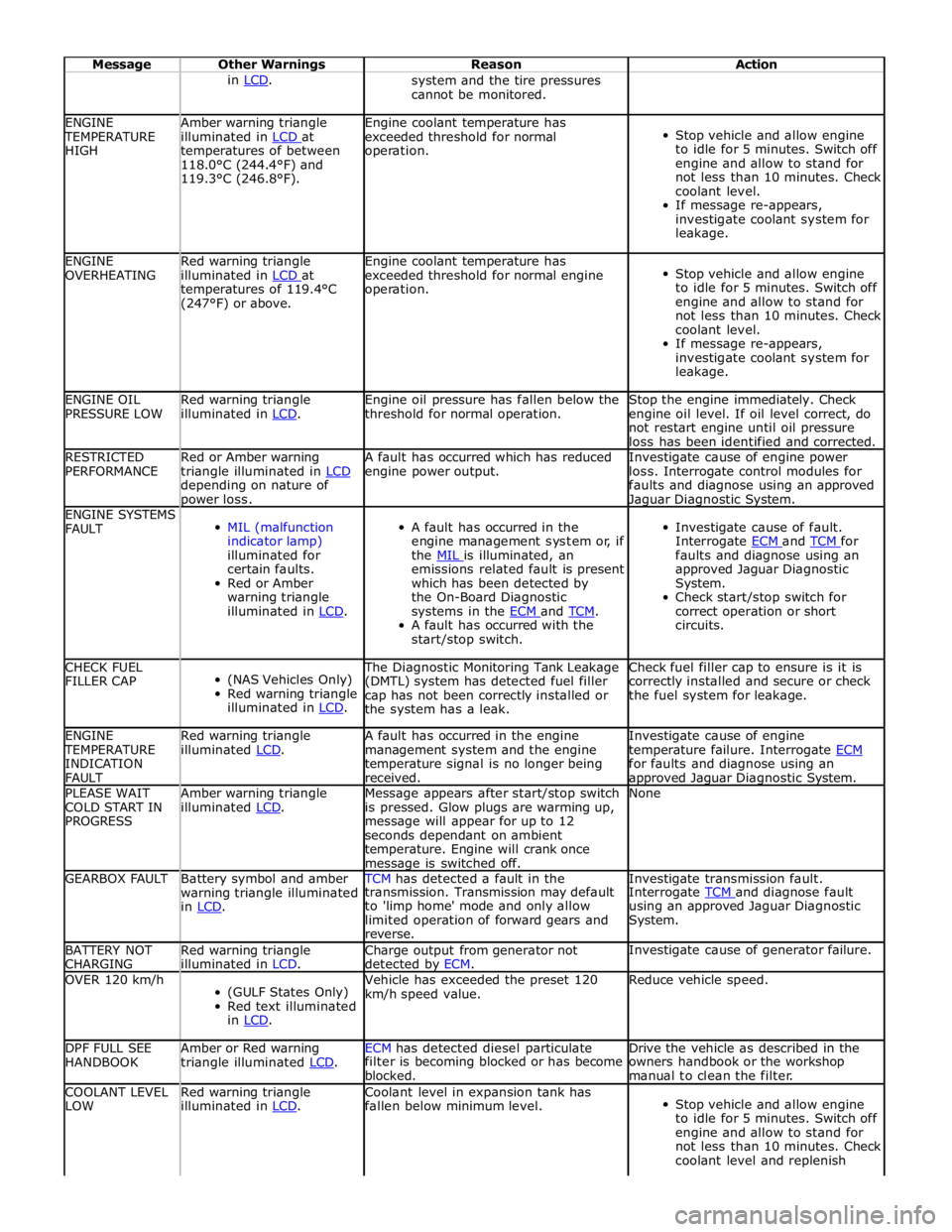
Message Other Warnings Reason Action in LCD. system and the tire pressures
cannot be monitored. ENGINE TEMPERATURE
HIGH Amber warning triangle
illuminated in LCD at temperatures of between
118.0°C (244.4°F) and
119.3°C (246.8°F). Engine coolant temperature has
exceeded threshold for normal
operation.
Stop vehicle and allow engine
to idle for 5 minutes. Switch off
engine and allow to stand for
not less than 10 minutes. Check
coolant level.
If message re-appears,
investigate coolant system for
leakage. ENGINE
OVERHEATING Red warning triangle
illuminated in LCD at temperatures of 119.4°C
(247°F) or above. Engine coolant temperature has
exceeded threshold for normal engine
operation.
Stop vehicle and allow engine
to idle for 5 minutes. Switch off
engine and allow to stand for
not less than 10 minutes. Check
coolant level.
If message re-appears,
investigate coolant system for
leakage. ENGINE OIL
PRESSURE LOW Red warning triangle
illuminated in LCD. Engine oil pressure has fallen below the
threshold for normal operation. Stop the engine immediately. Check
engine oil level. If oil level correct, do
not restart engine until oil pressure
loss has been identified and corrected. RESTRICTED
PERFORMANCE Red or Amber warning
triangle illuminated in LCD depending on nature of power loss. A fault has occurred which has reduced
engine power output. Investigate cause of engine power
loss. Interrogate control modules for
faults and diagnose using an approved Jaguar Diagnostic System. ENGINE SYSTEMS
FAULT
MIL (malfunction
indicator lamp)
illuminated for
certain faults.
Red or Amber
warning triangle
illuminated in LCD.
A fault has occurred in the
engine management system or, if
the MIL is illuminated, an emissions related fault is present
which has been detected by
the On-Board Diagnostic
systems in the ECM and TCM. A fault has occurred with the
start/stop switch.
Investigate cause of fault.
Interrogate ECM and TCM for faults and diagnose using an
approved Jaguar Diagnostic
System.
Check start/stop switch for
correct operation or short
circuits. CHECK FUEL
FILLER CAP
(NAS Vehicles Only)
Red warning triangle
illuminated in LCD. The Diagnostic Monitoring Tank Leakage
(DMTL) system has detected fuel filler
cap has not been correctly installed or
the system has a leak. Check fuel filler cap to ensure is it is
correctly installed and secure or check
the fuel system for leakage. ENGINE TEMPERATURE
INDICATION
FAULT Red warning triangle
illuminated LCD. A fault has occurred in the engine
management system and the engine
temperature signal is no longer being
received. Investigate cause of engine
temperature failure. Interrogate ECM for faults and diagnose using an approved Jaguar Diagnostic System. PLEASE WAIT
COLD START IN
PROGRESS Amber warning triangle
illuminated LCD. Message appears after start/stop switch
is pressed. Glow plugs are warming up,
message will appear for up to 12
seconds dependant on ambient
temperature. Engine will crank once message is switched off. None GEARBOX FAULT
Battery symbol and amber
warning triangle illuminated
in LCD. TCM has detected a fault in the Investigate transmission fault. transmission. Transmission may default
to 'limp home' mode and only allow
limited operation of forward gears and
reverse. Interrogate TCM and diagnose fault using an approved Jaguar Diagnostic
System. BATTERY NOT
CHARGING Red warning triangle
illuminated in LCD. Charge output from generator not
detected by ECM. Investigate cause of generator failure. OVER 120 km/h
(GULF States Only)
Red text illuminated
in LCD. Vehicle has exceeded the preset 120
km/h speed value. Reduce vehicle speed. DPF FULL SEE
HANDBOOK Amber or Red warning
triangle illuminated LCD. ECM has detected diesel particulate Drive the vehicle as described in the filter is becoming blocked or has become
blocked. owners handbook or the workshop
manual to clean the filter. COOLANT LEVEL
LOW Red warning triangle
illuminated in LCD. Coolant level in expansion tank has
fallen below minimum level.
Stop vehicle and allow engine
to idle for 5 minutes. Switch off
engine and allow to stand for
not less than 10 minutes. Check
coolant level and replenish