2010 JAGUAR XFR coolant temperature
[x] Cancel search: coolant temperaturePage 845 of 3039

Item Specification Camshaft journal maximum run out limit (mm) Camshaft journals to end journals 0.03 Camshaft journals to adjacent journals 0.015 Camshaft journal maximum out of round (mm) - all journals 0.005 Torque Specification
NOTE: A = Refer to procedure for correct torque sequence.
Description Nm lb-ft lb-in Engine cover mounting bolts 10 7 - Accessory drive belt tensioner retaining bolt 40 30 - Supercharger belt idler/tensioner bracket retaining bolts 25 18 - Secondary drive belt idler retaining bolts 40 30 - Power steering pump pulley retaining bolts 25 18 - Power steering pump retaining bolts 25 18 - Power steering pump bracket to engine retaining bolts 25 18 - Generator retaining bolts 48 35 - Starter motor retaining bolts 48 35 - Air conditioning compressor retaining bolts 25 18 - Engine mounting to engine mounting bracket retaining nuts 48 35 - Engine mounting to subframe retaining nuts 63 46 - Engine mounting bracket to engine retaining bolts 48 35 - Crankshaft damper pulley retaining LH threaded bolt 200 + 270° 148 + 180° - Flexplate retaining bolts 45 + 90° 33 + 90° - Exhaust manifold heat shield retaining bolts A - - Exhaust manifold retaining bolts A - - Engine wiring harness bracket retaining bolts 10 7 - Coolant outlet pipe 10 7 - Intercooler retaining bolts 25 18 - Intake manifold retaining bolts 25 18 - Oil Cooler retaining bolts 13 10 - Knock sensor (KS) retaining bolt 20 14 - Ignition coil retaining bolts 8 - 71 Spark plugs 20 15 - Fuel rail retaining bolts A - - High pressure fuel pipe retaining bolts A - - High pressure fuel pump retaining bolts 12 9 - Oil filter housing assembly retaining bolts 12 9 - Oil filter cap 28 21 - Lifting eye bolts 25 + 90° 18 + 90° - Manifold absolute pressure and temperature (MAPT) sensor sensor retaining bolts 5 - 44 Coolant pump retaining bolts 12 9 - Variable valve timing (VVT) oil control solenoid retaining bolts 10 7 - Camshaft position (CMP) sensor retaining bolts 10 7 - Camshaft cover retaining bolts 13 10 - Front upper timing cover retaining bolts 12 9 - Front lower timing cover retaining bolts A - - Engine rear cover retaining bolts A - - VVT to camshaft retaining bolts 32 24 - Camshaft bearing caps retaining bolts 11 8 - Primary timing chain fixed guide retaining bolts 12 9 - Primary timing chain tensioner retaining bolts 12 9 - Primary timing chain tensioner guide blade retaining bolts 25 18 - Auxiliary chain tensioner guide retaining bolts 21 15 - Auxiliary chain fixed guide retaining bolt 12 9 - Oil pump sprocket retaining bolt 21 15 - Cylinder head retaining bolts A - - Engine oil level (EOL) sensor retaining bolt 12 9 - Oil pan to oil sump body retaining bolts 12 9 - Oil sump body to engine retaining bolts 25 18 - Oil pan drain plug 23 17 - Oil transfer tube to Oil pan body retaining bolts 11 8 - Oil pump to engine block retaining bolts 25 18 - Pick-up pipe to oil pump retaining bolts 12 9 - Windage tray retaining bolts 25 18 - Piston cooling jet retaining bolts 12 9 - Engine block coolant draining plug 50 37 - Connecting Rod bolts Stage 1 10 7 - Stage 2 50 37 -
Page 1111 of 3039

Published: 11-May-2011
Engine Cooling - V8 5.0L Petrol/V8 S/C 5.0L Petrol - Engine Cooling - Overview
Description and Operation
OVERVIEW
The engine cooling system maintains the engine within an optimum temperature range under changing ambient and engine
operating conditions. The system is a pressurized expansion tank system with continuous bleeds to separate air from the
coolant and prevent the formation of air locks. The engine cooling system also provides:
Heating for:
- The passenger compartment. For additional information, refer to 412-01 Climate Control.
- The throttle body.
Cooling for:
- The engine oil cooler. For additional information, refer to 303-01F Engine - 5.0L, Vehicles With: Supercharger or
303-01E Engine - 5.0L, Vehicles Without: Supercharger.
- The transmission fluid cooler. For additional information, refer to 307-02B Transmission/Transaxle Cooling -
5.0L/3.0L Diesel.
The primary components of the engine cooling system are the:
Coolant pump.
Thermostat.
Radiator.
Auxiliary radiator (SC (supercharger) vehicles only).
Cooling fan.
Expansion tank.
Engine oil cooler.
Outlet tube and heater manifold.
Connecting hoses and pipes.
Page 1114 of 3039
14 Radiator 15 Auxiliary radiator 16 Connection with supercharger cooling system
System Operation
When the engine is running, the coolant is circulated around the engine cooling system by the coolant pump. From the coolant
pump, coolant flows through the cylinder heads and the engine oil cooler into the cylinder block and the heater manifold.
In the cylinder block, the coolant flows forwards to the outlet tube. When the coolant is cold, the thermostat is closed and the
coolant flows direct from the outlet tube back to the coolant pump. Once the coolant reaches operating temperature the
thermostat begins to open, to control system temperature, and coolant flows from the outlet tube to the coolant pump via the
radiator and, on SC (supercharger) vehicles, the auxiliary radiator. When the thermostat is open, the coolant flow through the
radiator(s) also generates a coolant flow through the transmission fluid cooler.
From the heater manifold the coolant flows through the electronic throttle and the heater core, in parallel circuits that are
unaffected by the position of the thermostat. From the electronic throttle, the coolant merges with bleed coolant from the
coolant pump and the outlet tube and flows to the expansion tank. From the heater core, the coolant flows back to the inlet of
the coolant pump.
Expansion and contraction of the coolant is accommodated by an air space in the expansion tank and the compliance of the
flexible hoses.
If the coolant level in the expansion tank decreases below a predetermined value, the level sensor connects a ground to the
instrument cluster, which activates the appropriate warning. For additional information, refer to 413-01 Instrument Cluster.
The cooling fan is operated by a fan control module integrated into the cooling fan motor. The fan control module regulates the
voltage, and thus speed, of the cooling fan motor in response to a PWM (pulse width modulation) signal from the ECM (engine
control module).
The cooling fan receives a battery feed and an ignition feed from the EJB (engine junction box). The ignition feed is supplied
from the main relay in the EJB, which is controlled by the ECM.
The ECM calculates the required fan speed from the engine temperature, A/C (air conditioning) system pressure and transmission fluid temperature. Under hot operating conditions, the fan may continue to operate for 4 minutes after the engine
has been switched off.
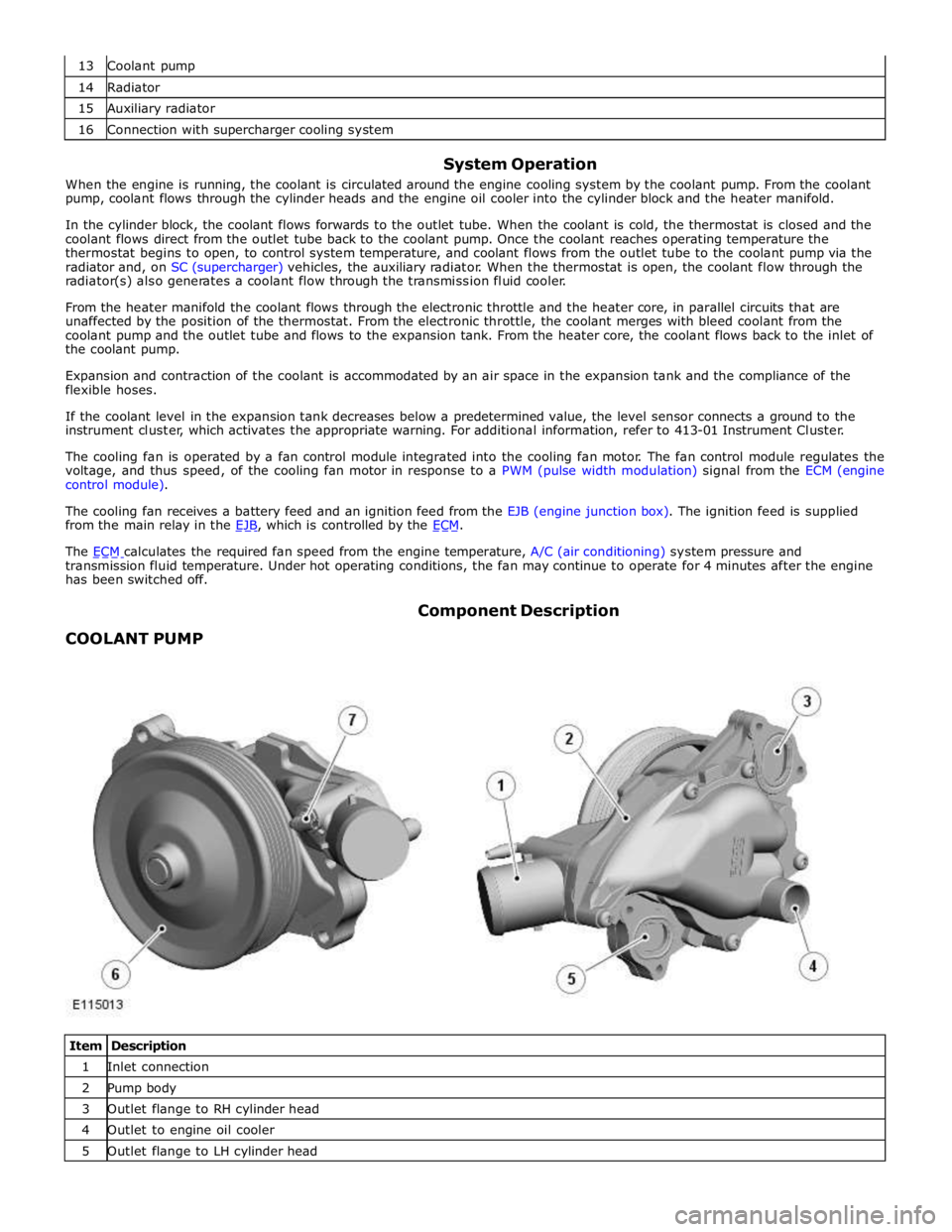
COOLANT PUMP Component Description
Item Description 1 Inlet connection 2 Pump body 3 Outlet flange to RH cylinder head 4 Outlet to engine oil cooler 5 Outlet flange to LH cylinder head
Page 1115 of 3039
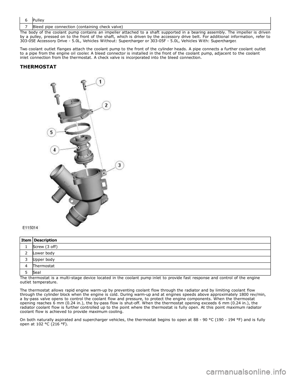
7 Bleed pipe connection (containing check valve) The body of the coolant pump contains an impeller attached to a shaft supported in a bearing assembly. The impeller is driven
by a pulley, pressed on to the front of the shaft, which is driven by the accessory drive belt. For additional information, refer to
303-05E Accessory Drive - 5.0L, Vehicles Without: Supercharger or 303-05F - 5.0L, Vehicles With: Supercharger.
Two coolant outlet flanges attach the coolant pump to the front of the cylinder heads. A pipe connects a further coolant outlet
to a pipe from the engine oil cooler. A bleed connector is installed in the front of the coolant pump, adjacent to the coolant
inlet connection from the thermostat. A check valve is incorporated into the bleed connection.
THERMOSTAT
Item Description 1 Screw (3 off) 2 Lower body 3 Upper body 4 Thermostat 5 Seal The thermostat is a multi-stage device located in the coolant pump inlet to provide fast response and control of the engine
outlet temperature.
The thermostat allows rapid engine warm-up by preventing coolant flow through the radiator and by limiting coolant flow
through the cylinder block when the engine is cold. During warm-up and at engines speeds above approximately 1800 rev/min,
a by-pass valve opens to control the coolant flow and pressure, to protect the engine components. When the thermostat
opening reaches 6 mm (0.24 in.), the by-pass flow is shut-off. When the thermostat opening exceeds 6 mm (0.24 in.), the
radiator coolant flow is further controlled up to the point where the thermostat is fully open. At this point maximum radiator
coolant flow is achieved to provide maximum cooling.
On both naturally aspirated and supercharger vehicles, the thermostat begins to open at 88 - 90 °C (190 - 194 °F) and is fully
open at 102 °C (216 °F).
Page 1121 of 3039
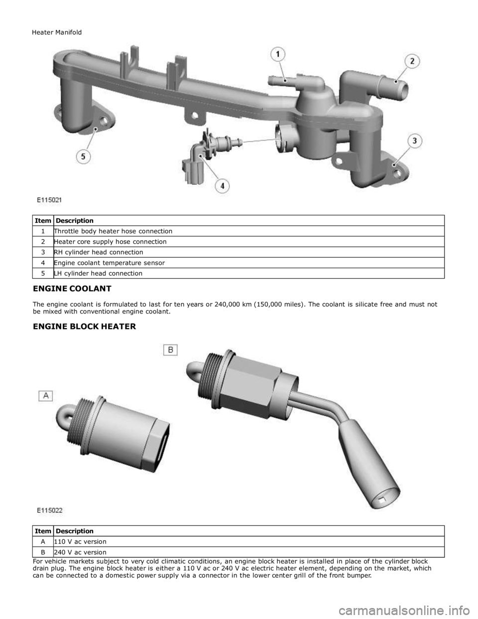
1 Throttle body heater hose connection 2 Heater core supply hose connection 3 RH cylinder head connection 4 Engine coolant temperature sensor 5 LH cylinder head connection
ENGINE COOLANT
The engine coolant is formulated to last for ten years or 240,000 km (150,000 miles). The coolant is silicate free and must not
be mixed with conventional engine coolant.
ENGINE BLOCK HEATER
Item Description A 110 V ac version B 240 V ac version For vehicle markets subject to very cold climatic conditions, an engine block heater is installed in place of the cylinder block
drain plug. The engine block heater is either a 110 V ac or 240 V ac electric heater element, depending on the market, which
can be connected to a domestic power supply via a connector in the lower center grill of the front bumper. Heater Manifold
Page 1122 of 3039
Published: 17-Apr-2014
Engine Cooling - V8 5.0L Petrol/V8 S/C 5.0L Petrol - Engine Cooling V8 5.0L
Petrol/V8 S/C 5.0L Petrol
Diagnosis and Testing
Principle of Operation
For a detailed description of the engine cooling system and operation, refer to the relevant description and operation section of
the workshop manual. Engine Cooling, Section - 303-03
Inspection and Verification
WARNING: Moving parts can cause severe injury, keep clear of moving parts, never place your hands or any part of your
body near to moving parts
CAUTION: Diagnosis by substitution from a donor vehicle is NOT acceptable. Substitution of control modules does not
guarantee confirmation of a fault and may also cause additional faults in the vehicle being checked and/or the donor vehicle
NOTES:
Check DDW for open campaigns. Refer to the corresponding bulletins and SSMs which may be valid for the specific
customer complaint and carry out the recommendations as required.
If the control module or a component is suspect and the vehicle remains under manufacturer warranty, refer to the
Warranty Policy and Procedures manual, or determine if any prior approval programme is in operation, prior to the installation
of a new module/component.
Check and rectify basic faults before beginning diagnostic routines involving pinpoint tests
1. Verify the customer concern
2. Visually inspect for obvious signs of mechanical or electrical damage
Visual Inspection
Mechanical Electrical
Coolant leaks
Coolant hoses
Coolant expansion tank
Radiator
Heater core
Accessory drive belt
Cooling fan
Fuses
Harnesses
Loose or corroded connector(s)
Engine coolant temperature sensor
3. If an obvious cause for an observed or reported concern is found, correct the cause (if possible) before proceeding to
the next step
4. If the cause is not visually evident, verify the symptom and refer to the symptom chart, alternatively check for
diagnostic trouble codes (DTCs) and refer to the DTC Index
Symptom Chart
Symptom Possible Causes Action Coolant loss
Hoses
Hose connections
Radiator
Water pump
Heater core
Gaskets
Engine casting cracks
Engine block core
plugs Carry out a visual inspection. If there are no obvious leaks, carry out a
cooling system pressure test. Rectify any leaks as necessary Overheating
Low/contaminated
coolant
Thermostat
Cooling fan Check the coolant level and condition. Carry out a cooling system pressure
test. Rectify any leaks as necessary. Check the thermostat and rectify as
necessary. Check the cooling fan operation, make sure the cooling fan
rotates freely. Check for obstructions to the air flow over the radiator.
Rectify as necessary
Page 1123 of 3039
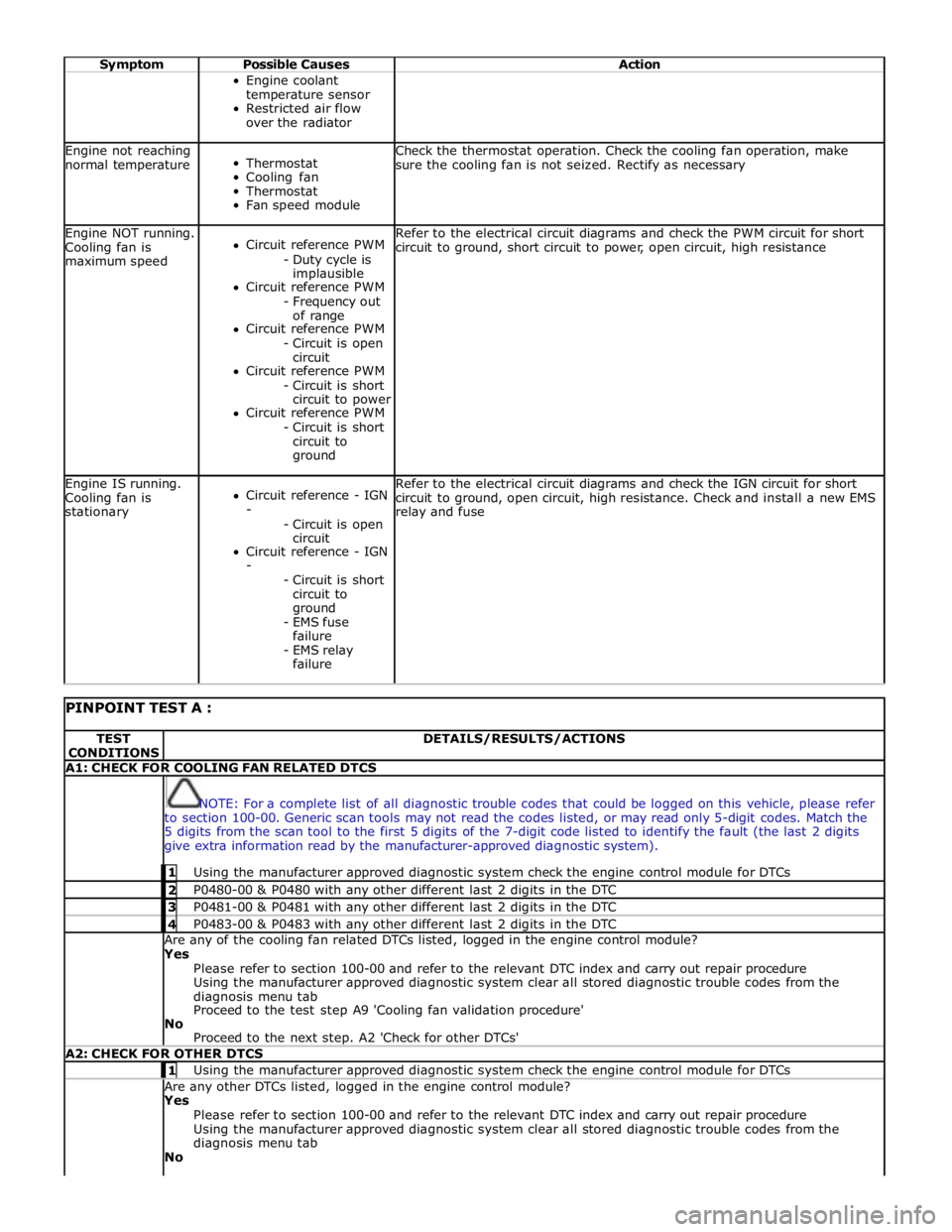
Symptom Possible Causes Action Engine coolant
temperature sensor
Restricted air flow
over the radiator Engine not reaching
normal temperature
Thermostat
Cooling fan
Thermostat
Fan speed module Check the thermostat operation. Check the cooling fan operation, make
sure the cooling fan is not seized. Rectify as necessary Engine NOT running.
Cooling fan is
maximum speed
Circuit reference PWM
- Duty cycle is
implausible
Circuit reference PWM
- Frequency out
of range
Circuit reference PWM
- Circuit is open
circuit
Circuit reference PWM
- Circuit is short
circuit to power
Circuit reference PWM
- Circuit is short
circuit to
ground Refer to the electrical circuit diagrams and check the PWM circuit for short
circuit to ground, short circuit to power, open circuit, high resistance Engine IS running.
Cooling fan is
stationary
Circuit reference - IGN
-
- Circuit is open
circuit
Circuit reference - IGN
-
- Circuit is short
circuit to
ground
- EMS fuse
failure
- EMS relay
failure Refer to the electrical circuit diagrams and check the IGN circuit for short
circuit to ground, open circuit, high resistance. Check and install a new EMS
relay and fuse
PINPOINT TEST A : TEST
CONDITIONS DETAILS/RESULTS/ACTIONS A1: CHECK FOR COOLING FAN RELATED DTCS
NOTE: For a complete list of all diagnostic trouble codes that could be logged on this vehicle, please refer
to section 100-00. Generic scan tools may not read the codes listed, or may read only 5-digit codes. Match the
5 digits from the scan tool to the first 5 digits of the 7-digit code listed to identify the fault (the last 2 digits
give extra information read by the manufacturer-approved diagnostic system). 1 Using the manufacturer approved diagnostic system check the engine control module for DTCs 2 P0480-00 & P0480 with any other different last 2 digits in the DTC 3 P0481-00 & P0481 with any other different last 2 digits in the DTC 4 P0483-00 & P0483 with any other different last 2 digits in the DTC Are any of the cooling fan related DTCs listed, logged in the engine control module?
Yes
Please refer to section 100-00 and refer to the relevant DTC index and carry out repair procedure
Using the manufacturer approved diagnostic system clear all stored diagnostic trouble codes from the
diagnosis menu tab
Proceed to the test step A9 'Cooling fan validation procedure'
No
Proceed to the next step. A2 'Check for other DTCs' A2: CHECK FOR OTHER DTCS 1 Using the manufacturer approved diagnostic system check the engine control module for DTCs Are any other DTCs listed, logged in the engine control module?
Yes
Please refer to section 100-00 and refer to the relevant DTC index and carry out repair procedure
Using the manufacturer approved diagnostic system clear all stored diagnostic trouble codes from the
diagnosis menu tab
No
Page 1125 of 3039

- Megafuse fixing nuts
Engine junction box
- Megafuse
- Megafuse fixing nuts
- Fuses
- Engine control module relay Were any circuits or wiring short circuit to ground, short circuit to power, open circuit, high resistance or any
connectors damaged from water ingress, pin damage and/or corrosion?
Yes
Rectify as required
No
Proceed to the next step. A9 'Cooling fan validation procedure' A9: COOLING FAN VALIDATION PROCEDURE 1 Ensure the hood is closed 2 Allow vehicle to idle 3 Switch ON air conditioning and set to lowest temperature and highest fan speed 4 Allow vehicle to reach operating temperature (approximately 90 degrees C). Using the manufacturer approved diagnostic system monitor datalogger signals – Engine Coolant Temperature (0XF405) -and -
Electric Fan PWM Control - Commanded (0X03F9) - as the engine coolant temperature reaches
operating temperature the fan speed should also increase between the values of 9 and 90% Did the cooling fan rotate at increasing speed as engine coolant temperature increased?
Yes
Return vehicle to customer
No
Contact dealer technical support DTC Index
For a list of diagnostic trouble codes (DTCs) that could be logged on this vehicle, please refer to Section 100-00.
REFER to: Electronic Engine Controls (303-14D Electronic Engine Controls - V8 S/C 5.0L Petrol, Diagnosis and Testing). www.JagDocs.com