2010 JAGUAR XFR bulb
[x] Cancel search: bulbPage 2063 of 3039

Interior Lighting - Interior Lighting
Diagnosis and Testing
Principles of Operation Published: 11-May-2011
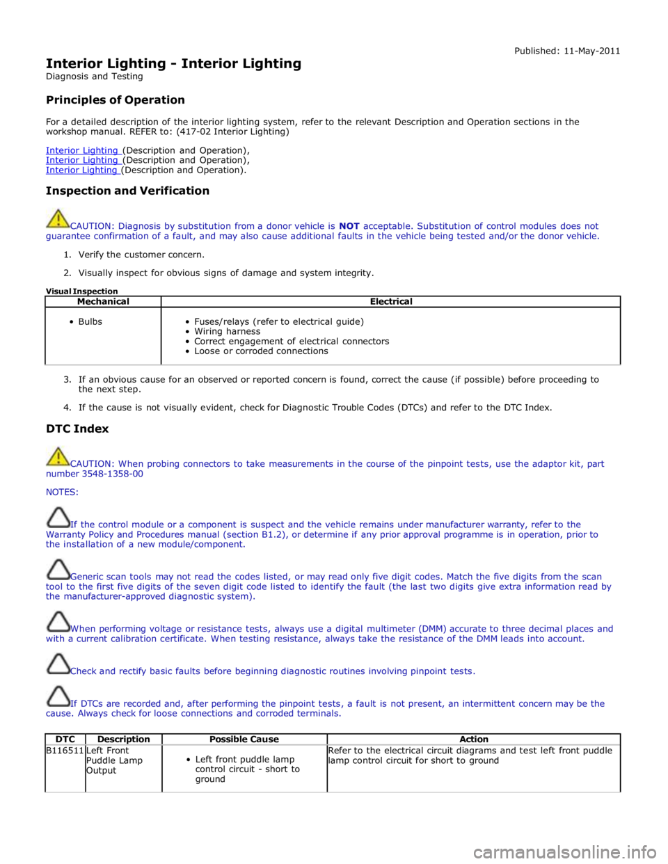
For a detailed description of the interior lighting system, refer to the relevant Description and Operation sections in the
workshop manual. REFER to: (417-02 Interior Lighting)
Interior Lighting (Description and Operation), Interior Lighting (Description and Operation), Interior Lighting (Description and Operation).
Inspection and Verification
CAUTION: Diagnosis by substitution from a donor vehicle is NOT acceptable. Substitution of control modules does not
guarantee confirmation of a fault, and may also cause additional faults in the vehicle being tested and/or the donor vehicle.
1. Verify the customer concern.
2. Visually inspect for obvious signs of damage and system integrity.
Visual Inspection
Mechanical Electrical
Bulbs
Fuses/relays (refer to electrical guide)
Wiring harness
Correct engagement of electrical connectors
Loose or corroded connections
3. If an obvious cause for an observed or reported concern is found, correct the cause (if possible) before proceeding to
the next step.
4. If the cause is not visually evident, check for Diagnostic Trouble Codes (DTCs) and refer to the DTC Index.
DTC Index
CAUTION: When probing connectors to take measurements in the course of the pinpoint tests, use the adaptor kit, part
number 3548-1358-00
NOTES:
If the control module or a component is suspect and the vehicle remains under manufacturer warranty, refer to the
Warranty Policy and Procedures manual (section B1.2), or determine if any prior approval programme is in operation, prior to
the installation of a new module/component.
Generic scan tools may not read the codes listed, or may read only five digit codes. Match the five digits from the scan
tool to the first five digits of the seven digit code listed to identify the fault (the last two digits give extra information read by
the manufacturer-approved diagnostic system).
When performing voltage or resistance tests, always use a digital multimeter (DMM) accurate to three decimal places and
with a current calibration certificate. When testing resistance, always take the resistance of the DMM leads into account.
Check and rectify basic faults before beginning diagnostic routines involving pinpoint tests.
If DTCs are recorded and, after performing the pinpoint tests, a fault is not present, an intermittent concern may be the
cause. Always check for loose connections and corroded terminals.
DTC Description Possible Cause Action B116511
Left Front
Puddle Lamp
Output
Left front puddle lamp
control circuit - short to
ground Refer to the electrical circuit diagrams and test left front puddle
lamp control circuit for short to ground
Page 2595 of 3039

Safety Belt System - Safety Belt System
Diagnosis and Testing
Principle of Operation Published: 13-Jun-2013
For a detailed description of the seatbelt system and operation, refer to the relevant description and operation section of the
workshop manual REFER to: (501-20A Safety Belt System)
Safety Belt System (Description and Operation), Safety Belt System (Description and Operation), Safety Belt System (Description and Operation).
Safety Information
WARNINGS:
To avoid accidental deployment the back-up power supply must be depleted before beginning any work on the SRS system
or its components. Failure to follow this instruction may result in personal injury
Do not use a multimeter to probe an SRS module. It is possible for the power from the multimeter battery to trigger the
activation of the module. Failure to follow this instruction may result in personal injury
NOTE: Do not to use a cellular phone or to have a cellular phone in close proximity when working on the SRS system or
components
Power supply depletion
Before beginning any work on the SRS system or related components:
1. Remove the ignition key
2. Disconnect the battery leads, ground first
3. Wait 2 minutes for the power circuit to discharge
There are comprehensive instructions on the correct procedures for SRS system repairs, refer to the relevant section of the
workshop manual
Inspection and Verification
CAUTION: Diagnosis by substitution from a donor vehicle is NOT acceptable. Substitution of control modules does not
guarantee confirmation of a fault and may also cause additional faults in the vehicle being checked and/or the donor vehicle
NOTE: Check and rectify basic faults before beginning diagnostic routines including pinpoint tests
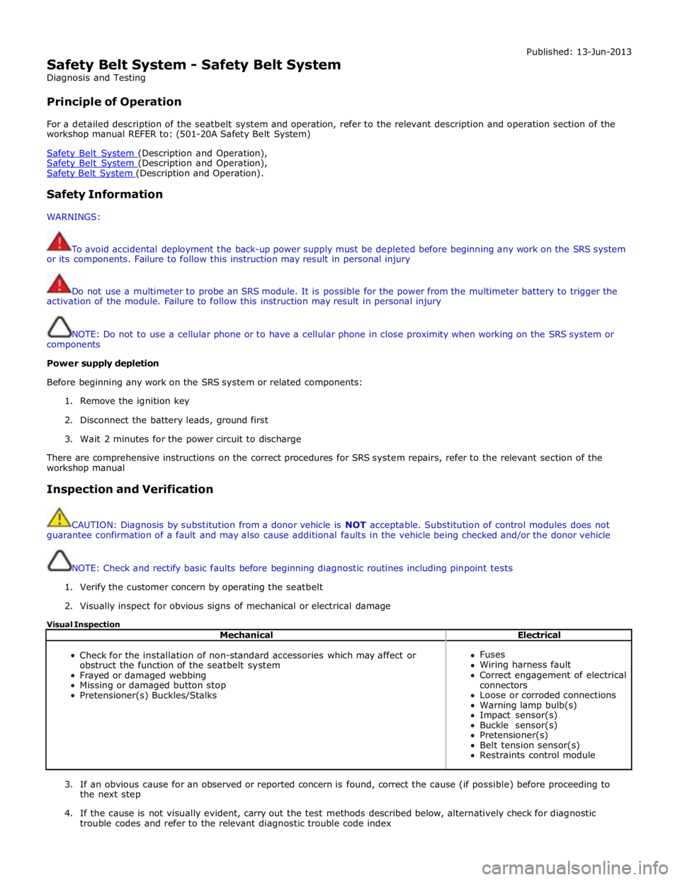
1. Verify the customer concern by operating the seatbelt
2. Visually inspect for obvious signs of mechanical or electrical damage
Visual Inspection
Mechanical Electrical
Check for the installation of non-standard accessories which may affect or
obstruct the function of the seatbelt system
Frayed or damaged webbing
Missing or damaged button stop
Pretensioner(s) Buckles/Stalks
Fuses
Wiring harness fault
Correct engagement of electrical
connectors
Loose or corroded connections
Warning lamp bulb(s)
Impact sensor(s)
Buckle sensor(s)
Pretensioner(s)
Belt tension sensor(s)
Restraints control module
3. If an obvious cause for an observed or reported concern is found, correct the cause (if possible) before proceeding to
the next step
4. If the cause is not visually evident, carry out the test methods described below, alternatively check for diagnostic
trouble codes and refer to the relevant diagnostic trouble code index
Page 2621 of 3039

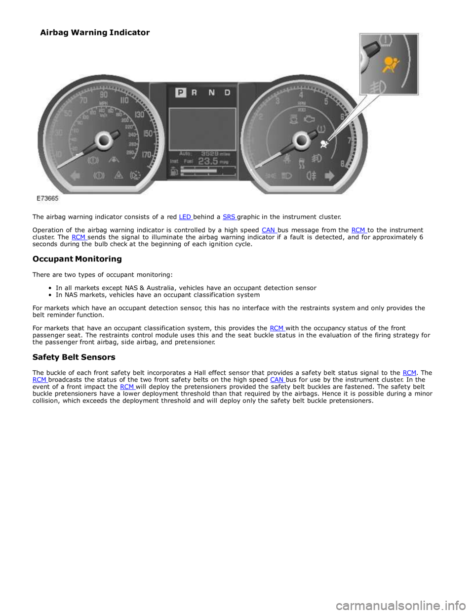
Operation of the airbag warning indicator is controlled by a high speed CAN bus message from the RCM to the instrument cluster. The RCM sends the signal to illuminate the airbag warning indicator if a fault is detected, and for approximately 6 seconds during the bulb check at the beginning of each ignition cycle.
Occupant Monitoring
There are two types of occupant monitoring:
In all markets except NAS & Australia, vehicles have an occupant detection sensor
In NAS markets, vehicles have an occupant classification system
For markets which have an occupant detection sensor, this has no interface with the restraints system and only provides the
belt reminder function.
For markets that have an occupant classification system, this provides the RCM with the occupancy status of the front passenger seat. The restraints control module uses this and the seat buckle status in the evaluation of the firing strategy for
the passenger front airbag, side airbag, and pretensioner.
Safety Belt Sensors
The buckle of each front safety belt incorporates a Hall effect sensor that provides a safety belt status signal to the RCM. The RCM broadcasts the status of the two front safety belts on the high speed CAN bus for use by the instrument cluster. In the event of a front impact the RCM will deploy the pretensioners provided the safety belt buckles are fastened. The safety belt buckle pretensioners have a lower deployment threshold than that required by the airbags. Hence it is possible during a minor
collision, which exceeds the deployment threshold and will deploy only the safety belt buckle pretensioners. Airbag Warning Indicator
Page 2624 of 3039

Published: 10-Jul-2014
Supplemental Restraint System - Air Bag and Safety Belt Pretensioner
Supplemental Restraint System (SRS)
Diagnosis and Testing
Principle of Operation
For a detailed description of the supplemental restraints system and operation, refer to the relevant Description and Operation
section in the workshop manual. REFER to: (501-20B Supplemental Restraint System)
Air Bag and Safety Belt Pretensioner Supplemental Restraint System (SRS) (Description and Operation), Air Bag and Safety Belt Pretensioner Supplemental Restraint System (SRS) (Description and Operation), Air Bag and Safety Belt Pretensioner Supplemental Restraint System (SRS) (Description and Operation).
Inspection and Verification
WARNING: TO AVOID ACCIDENTAL DEPLOYMENT AND POSSIBLE PERSONAL INJURY, THE BACKUP POWER SUPPLY MUST
BE DEPLETED BEFORE REPAIRING OR REPLACING ANY AIR BAG SUPPLEMENTAL RESTRAINT SYSTEM (SRS) COMPONENTS. TO
DEPLETE THE BACKUP POWER SUPPLY ENERGY, DISCONNECT THE BATTERY GROUND CABLE AND WAIT ONE MINUTE. FAILURE
TO FOLLOW THIS INSTRUCTION MAY RESULT IN PERSONAL INJURY.
CAUTION: Diagnosis by substitution from a donor vehicle is NOT acceptable. Substitution of control modules does not
guarantee confirmation of a fault, and may also cause additional faults in the vehicle being tested and/or the donor vehicle.
NOTE: Given the legal implications of a restraints system failure, harness repairs to Air Bag module circuits are not
acceptable. Where the text refers to "REPAIR the circuit", this will normally mean the replacement of a harness.
1. Verify the customer concern.
2. Visually inspect for obvious signs of damage and system integrity.
3. If an obvious cause for an observed or reported concern is found, correct the cause (if possible) before proceeding to
the next step.
4. If the cause is not visually evident, check for Diagnostic Trouble Codes (DTCs) and refer to the DTC Index.
DTC Index
For a list of Diagnostic Trouble Codes (DTCs) that could be logged on this vehicle, please refer to Section 100-00.
REFER to: Diagnostic Trouble Code (DTC) Index - DTC: Restraints Control Module (RCM) (100-00 General Information, Description and Operation). Electrical
Battery condition, state of charge
Make sure all electrical connector(s) are engaged correctly on the air bag circuits
Wiring harness
Air bag module(s)
Make sure the restraints control module (RCM) is correctly installed
Fuse(s)
Sensor(s)
Pretensioner(s)
Warning lamp bulb(s) Visual Inspection
www.JagDocs.com