2010 JAGUAR XFR Map sensor
[x] Cancel search: Map sensorPage 1584 of 3039

the flow and pressure supplied by controlling the operation of the fuel pump using a PWM (pulse width modulation) output. A
LP sensor is located in the fuel feed supply line to the engine and is monitored by the ECM for fuel pump control.
Two fuel level sensors are installed in either side of the saddle tank. The sensors are a MAPPS (magnetic passive position
sensor) which provide a variable resistance to ground for the output from the fuel gage.
The fuel system also incorporates an EVAP (evaporative emission) system which is part of the on-board refueling and vapor
recovery feature. The function and operation of the system is designed to meet EVAP requirements to minimize fuel vapor losses.
Page 1590 of 3039
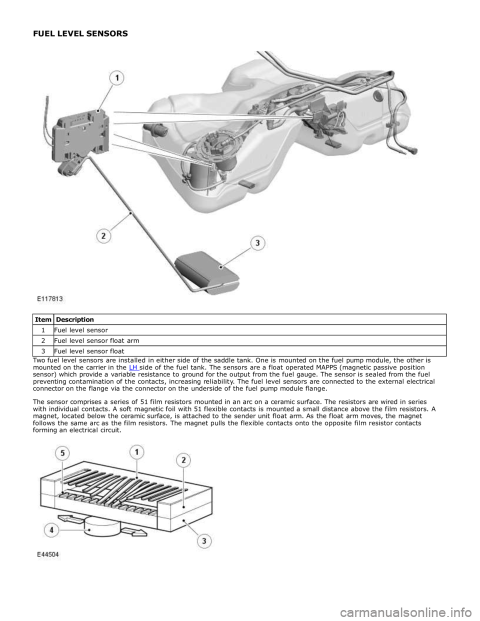
1 Fuel level sensor 2 Fuel level sensor float arm 3 Fuel level sensor float Two fuel level sensors are installed in either side of the saddle tank. One is mounted on the fuel pump module, the other is
mounted on the carrier in the LH side of the fuel tank. The sensors are a float operated MAPPS (magnetic passive position sensor) which provide a variable resistance to ground for the output from the fuel gauge. The sensor is sealed from the fuel
preventing contamination of the contacts, increasing reliability. The fuel level sensors are connected to the external electrical
connector on the flange via the connector on the underside of the fuel pump module flange.
The sensor comprises a series of 51 film resistors mounted in an arc on a ceramic surface. The resistors are wired in series
with individual contacts. A soft magnetic foil with 51 flexible contacts is mounted a small distance above the film resistors. A
magnet, located below the ceramic surface, is attached to the sender unit float arm. As the float arm moves, the magnet
follows the same arc as the film resistors. The magnet pulls the flexible contacts onto the opposite film resistor contacts
forming an electrical circuit.
Page 1826 of 3039
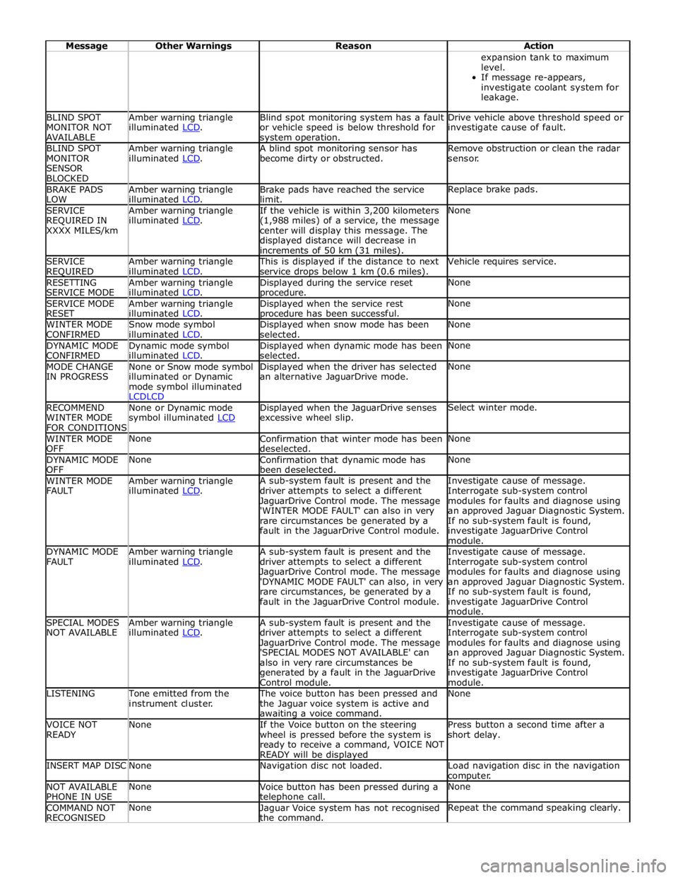
Message Other Warnings Reason Action expansion tank to maximum
level.
If message re-appears,
investigate coolant system for
leakage. BLIND SPOT
MONITOR NOT
AVAILABLE Amber warning triangle
illuminated LCD. Blind spot monitoring system has a fault
or vehicle speed is below threshold for system operation. Drive vehicle above threshold speed or
investigate cause of fault. BLIND SPOT
MONITOR
SENSOR
BLOCKED Amber warning triangle
illuminated LCD. A blind spot monitoring sensor has
become dirty or obstructed. Remove obstruction or clean the radar
sensor. BRAKE PADS
LOW Amber warning triangle
illuminated LCD. Brake pads have reached the service
limit. Replace brake pads. SERVICE
REQUIRED IN
XXXX MILES/km Amber warning triangle
illuminated LCD. If the vehicle is within 3,200 kilometers
(1,988 miles) of a service, the message
center will display this message. The
displayed distance will decrease in
increments of 50 km (31 miles). None SERVICE
REQUIRED Amber warning triangle
illuminated LCD. This is displayed if the distance to next
service drops below 1 km (0.6 miles). Vehicle requires service. RESETTING
SERVICE MODE Amber warning triangle
illuminated LCD. Displayed during the service reset procedure. None SERVICE MODE
RESET Amber warning triangle
illuminated LCD. Displayed when the service rest procedure has been successful. None WINTER MODE
CONFIRMED Snow mode symbol
illuminated LCD. Displayed when snow mode has been
selected. None DYNAMIC MODE
CONFIRMED Dynamic mode symbol
illuminated LCD. Displayed when dynamic mode has been
selected. None MODE CHANGE
IN PROGRESS None or Snow mode symbol
illuminated or Dynamic
mode symbol illuminated
LCDLCD Displayed when the driver has selected
an alternative JaguarDrive mode. None RECOMMEND
WINTER MODE
FOR CONDITIONS None or Dynamic mode
symbol illuminated LCD Displayed when the JaguarDrive senses
excessive wheel slip. Select winter mode. WINTER MODE
OFF None
Confirmation that winter mode has been
deselected. None DYNAMIC MODE
OFF None
Confirmation that dynamic mode has
been deselected. None WINTER MODE
FAULT Amber warning triangle
illuminated LCD. A sub-system fault is present and the
driver attempts to select a different
JaguarDrive Control mode. The message
'WINTER MODE FAULT' can also in very
rare circumstances be generated by a
fault in the JaguarDrive Control module. Investigate cause of message.
Interrogate sub-system control
modules for faults and diagnose using
an approved Jaguar Diagnostic System.
If no sub-system fault is found,
investigate JaguarDrive Control
module. DYNAMIC MODE
FAULT Amber warning triangle
illuminated LCD. A sub-system fault is present and the
driver attempts to select a different
JaguarDrive Control mode. The message
'DYNAMIC MODE FAULT' can also, in very
rare circumstances, be generated by a
fault in the JaguarDrive Control module. Investigate cause of message.
Interrogate sub-system control
modules for faults and diagnose using
an approved Jaguar Diagnostic System.
If no sub-system fault is found,
investigate JaguarDrive Control
module. SPECIAL MODES
NOT AVAILABLE Amber warning triangle
illuminated LCD. A sub-system fault is present and the
driver attempts to select a different
JaguarDrive Control mode. The message
'SPECIAL MODES NOT AVAILABLE' can
also in very rare circumstances be
generated by a fault in the JaguarDrive
Control module. Investigate cause of message.
Interrogate sub-system control
modules for faults and diagnose using
an approved Jaguar Diagnostic System.
If no sub-system fault is found,
investigate JaguarDrive Control
module. LISTENING Tone emitted from the
instrument cluster. The voice button has been pressed and
the Jaguar voice system is active and awaiting a voice command. None VOICE NOT
READY None
If the Voice button on the steering
wheel is pressed before the system is
ready to receive a command, VOICE NOT
READY will be displayed Press button a second time after a
short delay. INSERT MAP DISC None Navigation disc not loaded.
Load navigation disc in the navigation
computer. NOT AVAILABLE
PHONE IN USE None
Voice button has been pressed during a telephone call. None COMMAND NOT
RECOGNISED None
Jaguar Voice system has not recognised
the command. Repeat the command speaking clearly.
Page 1979 of 3039
VICS (vehicle information and communication system) receiver (Japan only)
TMC (traffic message channel) receiver (Europe only)
JaguarVoice control module
The navigation computer contains a solid state piezo gyro which measures the motion of the vehicle around its vertical axis.
The gyro operates on the principle known as the coriolis force. The coriolis force is the force that appears to accelerate a body
moving away from its rotational axis against the direction of rotation of the axis.
Using inputs from the ABS module, the GPS antenna and the gyro sensor, the computer calculates the vehicle's current position, direction and speed.
The navigation computer houses the DVD (digital versatile disc) drive. The drive is used to read map data from region specific
DVD's. The number of DVD's issued per region varies depending on the amount of information available. The regions are as follows:
Europe (2 versions, Western Europe and Whole of Europe)
NAS (North American specification)
Japan, Middle East, Australia and South Africa
A button, located adjacent to the DVD slot, is provided to eject the DVD from the unit. Prior to ejecting the disc the slot protection has to be slid to the side. If the ignition is on, or the entertainment system is in 1-hour mode, one press of the
button will eject the DVD.
The navigation computer uses non-volatile memory to store settings and configuration information when it is powered down.
This process takes place just before the computer turns off.
No configuration procedure is required if the navigation computer is replaced. There is no option to calibrate the navigation
computer using the Jaguar approved diagnostic equipment; however in some regions a software download, contained in the
DVD disc, is required before the navigation system becomes operational.
MICROPHONE
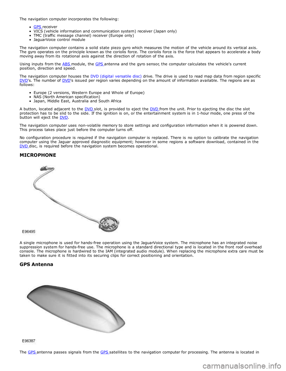
A single microphone is used for hands-free operation using the JaguarVoice system. The microphone has an integrated noise
suppression system for hands-free use. The microphone is a standard directional type and is located in the front roof overhead
console. The microphone is hardwired to the IAM (integrated audio module). When replacing the microphone extra care must be
taken to make sure it is fitted into its securing clips for correct positioning and orientation.
GPS Antenna
The GPS antenna passes signals from the GPS satellites to the navigation computer for processing. The antenna is located in
Page 2055 of 3039
Interior Lighting - Interior Lighting - Overview
Description and Operation
OVERVIEW Published: 11-May-2011
Interior lighting is provided to enable the safe entry and departure from the vehicle for the driver and passengers in low
ambient light conditions, without any manual switching of the lights.
NOTE: The term interior lamps also includes the door mirror approach lamps.
The interior lamps are controlled by the CJB (central junction box) and the RJB (rear junction box) and have 2 modes of
operation: manual and automatic. The front interior lamps in the front overhead console are operated using the 'JaguarSense'
system. The system uses capacitive proximity sensor technology for the switch operation which is integral with the overhead
console. The rear overhead console interior lamps have conventional switches.
In the manual mode the interior lamps can be switched on and off with the JaguarSense system. Positioning your hand
adjacent to each lamp in the front overhead console will switch interior lamps on or off and completely disable the interior
lamp system. In the automatic mode the interior lamp functionality is controlled by the CJB and the RJB and reacts to the vehicle being locked or unlocked and opening the vehicle doors.
In manual mode the interior lamps can be operated by placing your finger(s) close to, or touch, the surface of the appropriate
lamp. The courtesy light and map reading lamps can be operated manually by the 'JaguarSense' system. When in automatic
mode, the courtesy lamp functionality is also controlled by the CJB and the RJB and reacts to the vehicle being locked or unlocked and opening the vehicle doors. To deactivate or activate automatic illumination, touch the front courtesy lamp for
approximately 2 seconds
The driver's and passenger door approach lamps are controlled by the driver's door module and the passenger door module
respectively and operate with the automatic mode. The door modules receive a power supply from the RJB and receive information to illuminate the approach lamps on the medium speed CAN (controller area network) bus from the RJB and the CJB. www.JagDocs.com
Page 2060 of 3039
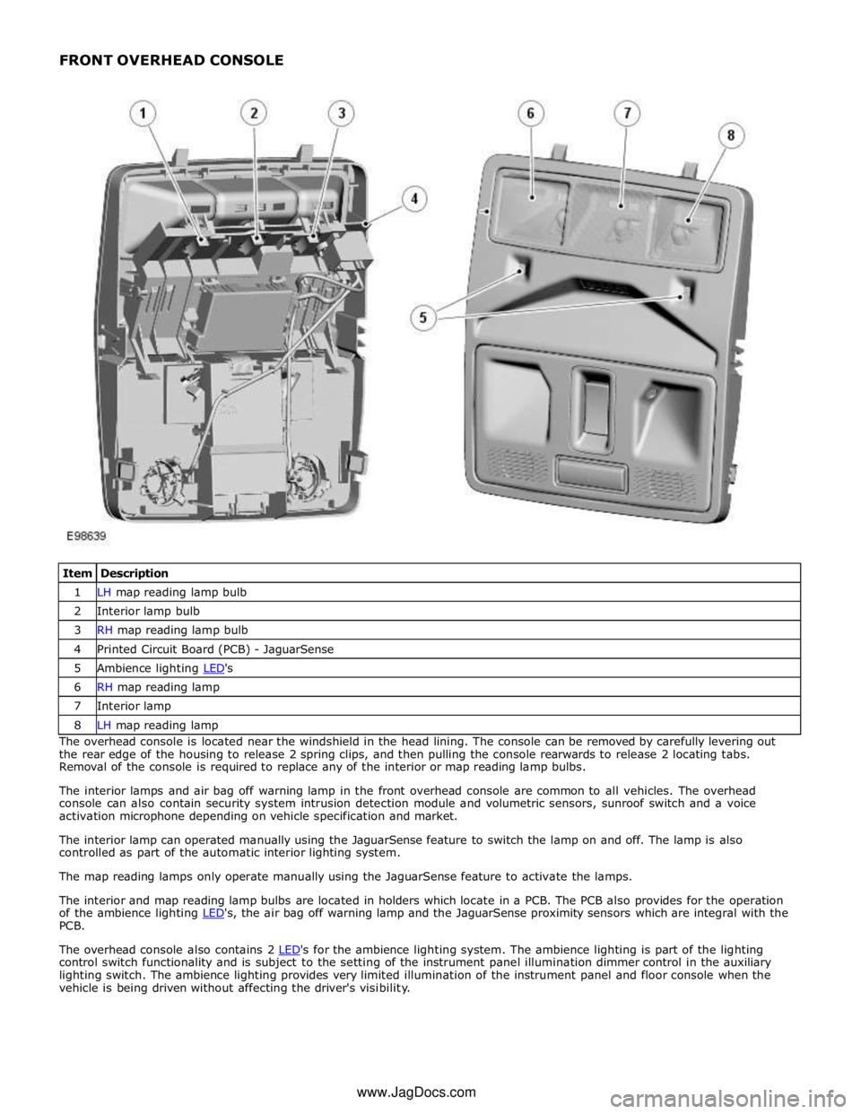
1 LH map reading lamp bulb 2 Interior lamp bulb 3 RH map reading lamp bulb 4 Printed Circuit Board (PCB) - JaguarSense 5 Ambience lighting LED's 6 RH map reading lamp 7 Interior lamp 8 LH map reading lamp The overhead console is located near the windshield in the head lining. The console can be removed by carefully levering out
the rear edge of the housing to release 2 spring clips, and then pulling the console rearwards to release 2 locating tabs.
Removal of the console is required to replace any of the interior or map reading lamp bulbs.
The interior lamps and air bag off warning lamp in the front overhead console are common to all vehicles. The overhead
console can also contain security system intrusion detection module and volumetric sensors, sunroof switch and a voice
activation microphone depending on vehicle specification and market.
The interior lamp can operated manually using the JaguarSense feature to switch the lamp on and off. The lamp is also
controlled as part of the automatic interior lighting system.
The map reading lamps only operate manually using the JaguarSense feature to activate the lamps.
The interior and map reading lamp bulbs are located in holders which locate in a PCB. The PCB also provides for the operation
of the ambience lighting LED's, the air bag off warning lamp and the JaguarSense proximity sensors which are integral with the PCB.
The overhead console also contains 2 LED's for the ambience lighting system. The ambience lighting is part of the lighting control switch functionality and is subject to the setting of the instrument panel illumination dimmer control in the auxiliary
lighting switch. The ambience lighting provides very limited illumination of the instrument panel and floor console when the
vehicle is being driven without affecting the driver's visibility. www.JagDocs.com
Page 2152 of 3039
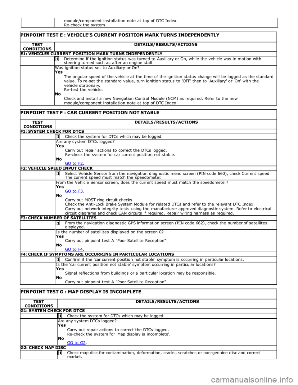
TEST
CONDITIONS DETAILS/RESULTS/ACTIONS E1: VEHICLES CURRENT POSITION MARK TURNS INDEPENDENTLY 1 Determine if the ignition status was turned to Auxiliary or On, while the vehicle was in motion with steering turned such as after an engine stall. Was ignition status set to Auxiliary or On?
Yes
The angular speed of the vehicle at the time of the ignition status change will be logged as the standard
value. To re-set the standard value, turn ignition status to 'OFF' then to 'Auxiliary' or 'On' with the
vehicle stationary.
Re-test the vehicle.
No
Check and install a new Navigation Control Module (NCM) as required. Refer to the new module/component installation note at top of DTC Index.
PINPOINT TEST F : CAR CURRENT POSITION NOT STABLE TEST
CONDITIONS DETAILS/RESULTS/ACTIONS F1: SYSTEM CHECK FOR DTCS 1 Check the system for DTCs which may be logged. Are any system DTCs logged? Yes
Carry out repair actions to correct the DTCs logged.
Re-check the system for car current position not stable.
No
GO to F2. F2: VEHICLE SPEED INPUT CHECK 1 Select Vehicle Sensor from the navigation diagnostic menu screen (PIN code 660), check Current speed. The current speed must match the speedometer. From the Vehicle Sensor screen, does the current speed must match the speedometer? Yes
GO to F3. No
Carry out MOST ring circuit checks.
Check the Anti-Lock Brake System Module for related DTCs and refer to the relevant DTC Index.
Carry out network integrity tests using the manufacturer approved diagnostic system. Refer to electrical
circuit diagrams and check CAN circuits if required. Repair wiring harness as required. F3: CHECK NUMBER OF SATELLITES 1 From the navigation diagnostic GPS information screen (PIN code 662), check the number of satellites displayed. Is the number of satellites displayed on the screen 0? Yes
Carry out pinpoint test A "Poor Satellite Reception"
No
GO to F4. F4: CHECK IF SYMPTOMS ARE OCCURRING IN PARTICULAR LOCATIONS 1 Confirm if the 'car current position not stable' symptom is occurring in particular locations. Is the 'car current position not stable' symptom occurring in particular locations? Yes
Signal reflections from buildings or a particular location may be responsible.
No
Carry out pinpoint test A "Poor Satellite Reception"
PINPOINT TEST G : MAP DISPLAY IS INCOMPLETE TEST
CONDITIONS DETAILS/RESULTS/ACTIONS G1: SYSTEM CHECK FOR DTCS 1 Check the system for DTCs which may be logged. Are any system DTCs logged? Yes
Carry out repair actions to correct the DTCs logged.
Re-check the system for 'Map display is incomplete'.
No
GO to G2. G2: CHECK MAP DISC 1 Check map disc for contamination, deformation, cracks, scratches or non-genuine disc and correct market. module/component installation note at top of DTC Index.
Re-check the system.
Page 2172 of 3039
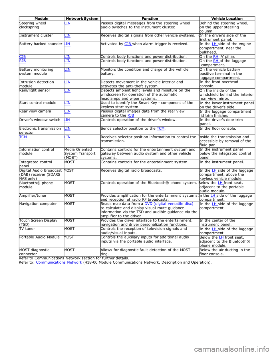
Module Network System Function Vehicle Location
Steering wheel
clockspring LIN Passes digital messages from the steering wheel
audio switches to the instrument cluster. Behind the steering wheel,
on the upper steering
column.
Instrument cluster LIN Receives digital signals from other vehicle systems. On the driver's side of the
instrument panel.
Battery backed sounder LIN Activated by CJB when alarm trigger is received. In the LH side of the engine compartment, near the
bulkhead.
CJB LIN Controls body functions and power distribution. On the RH 'A' pillar.
RJB LIN Controls body functions and power distribution. On the RH of the luggage compartment.
Battery monitoring
system module
Intrusion detection
module LIN Monitors the condition and charge of the vehicle
battery.
LIN Detects movement in the vehicle interior and
activates the anti-theft system. On the vehicle battery
positive terminal in the
luggage compartment.
In the front overhead
console.
Rain/light sensor LIN Detects ambient light levels and moisture on the
windscreen for operation of the automatic
headlamps and wiper systems.
Start control module LIN Used to identify the Smart Key - component of the
keyless start system.
Rear view camera LIN Passes digital images data from the rear view
camera to the RJB On the inside of the
windshield behind the interior
rear view mirror.
In the lower instrument panel
on the driver's side.
In the luggage compartment
lid trim finisher.
Driver's window switch LIN Controls operation of the driver's window. In the driver's door trim
panel.
Electronic transmission
selector LIN Sends selector position to the TCM. In the floor console. TCM LIN Receives selector position information to control the Inside the transmission and
Information control
module
Media Oriented
System Transport
(MOST) transmission.
Contains controls for the entertainment system and
gateway between audio system and other vehicle
systems. accessible by removal of the
fluid pan.
In the instrument panel
below the integrated control
panel.
Integrated control
panel MOST Contains controls for the entertainment system. In the instrument panel.
Digital Audio Broadcast MOST Receives digital radio broadcasts. In the LH side of the luggage (DAB) receiver (SDARS
NAS only)
Bluetooth® phone
module compartment, above the
keyless vehicle module.
MOST Controls operation of the Bluetooth® phone system. Below the LH front seat, adjacent to the portable
audio module.
Amplifier/tuner MOST Provides amplification for the entertainment systems In the LH side of the luggage and reception of radio RF broadcasts.
Navigation computer MOST Reads map data from a DVD (digital versatile disc)
to calculate and display visual route guidance
information via the TSD and audible guidance via the
amplifier to the driver. compartment.
In the LH side of the luggage compartment.
Touch Screen Display
(TSD) MOST Provides the driver interface to the entertainment,
navigation and driver personalization functions. In the center of the
instrument panel.
TV tuner MOST Controls the reception of television signals and
audio/visual inputs.
Portable Audio Module MOST Controls the auxiliary inputs for additional audio
inputs via the portable audio interface. In the LH side of the luggage compartment.
Below the LH front seat, adjacent to the Bluetooth®
phone module.
MOST diagnostic
connector MOST Allows for diagnostic fault detection of the MOST
ring. Below the air ducting in the
floor console.
Refer to Communications Network section for further details.
Refer to: Communications Network (418-00 Module Communications Network, Description and Operation).