2010 JAGUAR XFR diagram
[x] Cancel search: diagramPage 1881 of 3039
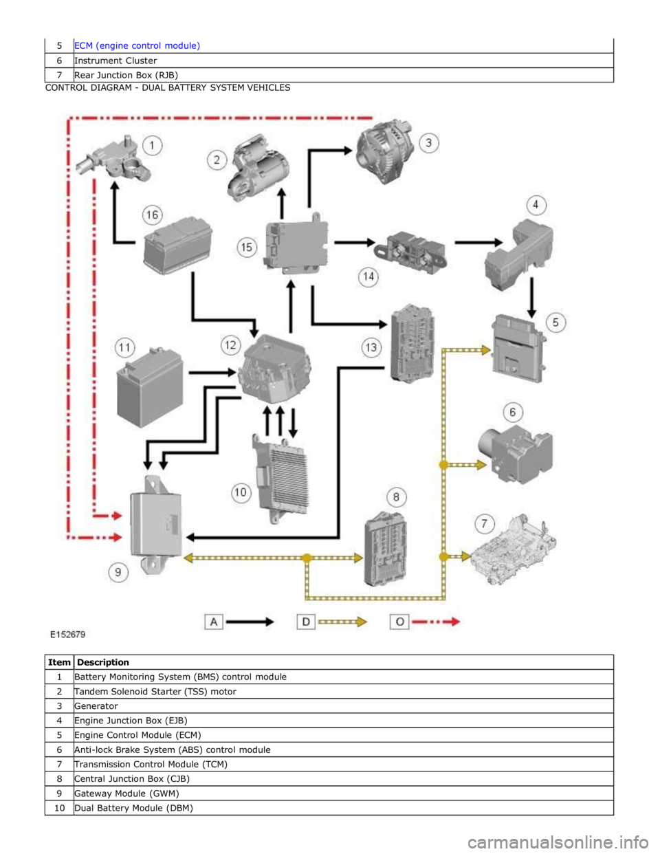
6 Instrument Cluster 7 Rear Junction Box (RJB) CONTROL DIAGRAM - DUAL BATTERY SYSTEM VEHICLES
Item Description 1 Battery Monitoring System (BMS) control module 2 Tandem Solenoid Starter (TSS) motor 3 Generator 4 Engine Junction Box (EJB) 5 Engine Control Module (ECM) 6 Anti-lock Brake System (ABS) control module 7 Transmission Control Module (TCM) 8 Central Junction Box (CJB) 9 Gateway Module (GWM) 10 Dual Battery Module (DBM)
Page 1911 of 3039
Published: 11-May-2011
Generator and Regulator - V8 5.0L Petrol/V8 S/C 5.0L Petrol - Generator - System Operation and Component Description
Description and Operation
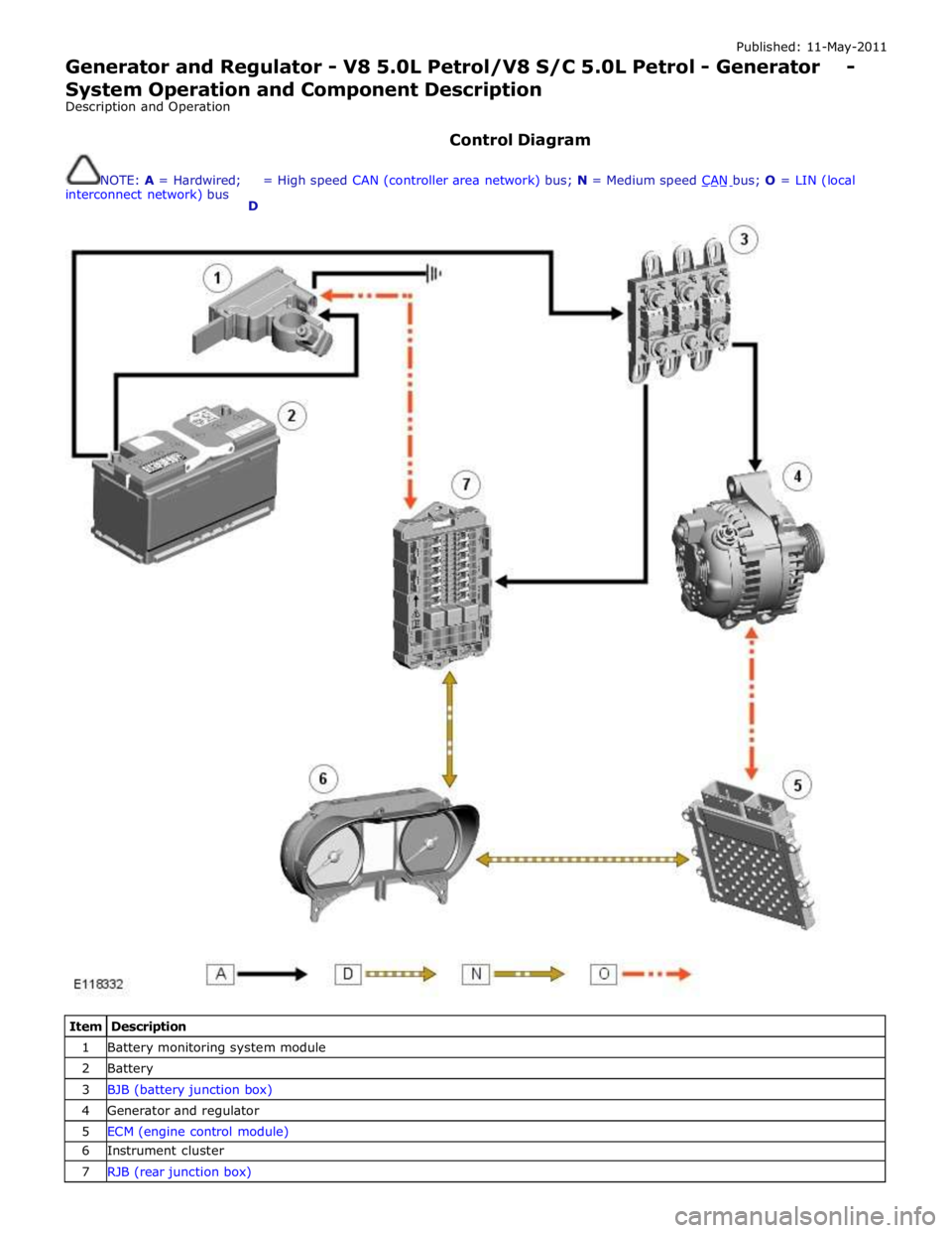
Control Diagram
NOTE: A = Hardwired;
interconnect network) bus
D = High speed CAN (controller area network) bus; N = Medium speed CAN bus; O = LIN (local
Item Description 1 Battery monitoring system module 2 Battery 3 BJB (battery junction box) 4 Generator and regulator 5 ECM (engine control module) 6 Instrument cluster 7 RJB (rear junction box)
Page 1935 of 3039
Check and rectify basic faults before beginning diagnostic routines involving pinpoint tests.
If DTCs are recorded and, after performing the pinpoint tests, a fault is not present, an intermittent concern may be the
cause. Always check for loose connections and corroded terminals.
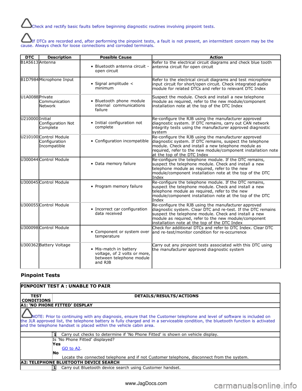
DTC Description Possible Cause Action B1A5613 Antenna
Bluetooth antenna circuit -
open circuit Refer to the electrical circuit diagrams and check blue tooth
antenna circuit for open circuit B1D7984 Microphone Input
Signal amplitude <
minimum Refer to the electrical circuit diagrams and test microphone
input circuit for short/open circuit. Check integrated audio
module for related DTCs and refer to relevant DTC Index U1A0088
Private
Communication
Network
Bluetooth phone module
internal communications
failure Suspect the module. Check and install a new telephone
module as required, refer to the new module/component
installation note at the top of the DTC Index U210000
Initial
Configuration Not
Complete
Initial configuration not
complete Re-configure the RJB using the manufacturer approved
diagnostic system. If DTC remains, carry out CAN network
integrity tests using the manufacturer approved diagnostic system U210100
Control Module
Configuration
Incompatible
Configuration incompatible Re-configure the RJB using the manufacturer approved
diagnostic system. If DTC remains, suspect the telephone
module. Check and install a new telephone module as
required, refer to the new module/component installation note
at the top of the DTC Index U300044 Control Module
Data memory failure Re-configure the telephone module. If the DTC remains,
suspect the telephone module. Check and install a new
telephone module as required, refer to the new
module/component installation note at the top of the DTC
Index U300045 Control Module
Program memory failure Re-configure the telephone module. If the DTC remains,
suspect the telephone module. Check and install a new
telephone module as required, refer to the new
module/component installation note at the top of the DTC
Index U300055 Control Module
Incorrect car configuration
data received Re-configure the RJB using the manufacturer approved
diagnostic system. Clear DTC and re-test. If the DTC remains
suspect the telephone module. Check and install a new
module as required, refer to the new module/component
installation note at the top of the DTC Index U300098 Control Module
Component or system over
temperature Check for additional DTCs and refer to DTC Index. Clear DTC
and re-test/monitor condition for re-occurrence U300362 Battery Voltage
Mis-match in battery
voltage, of 2 volts or more,
between telephone module
and RJB Carry out any pinpoint tests associated with this DTC using
the manufacturer approved diagnostic system
Pinpoint Tests
PINPOINT TEST A : UNABLE TO PAIR TEST
CONDITIONS DETAILS/RESULTS/ACTIONS A1: 'NO PHONE FITTED' DISPLAY
NOTE: Prior to continuing with any diagnosis, ensure that the Customer telephone and level of software is included on
the JLR approved list, the telephone battery is fully charged and in a serviceable condition, the bluetooth function is activated
and the telephone handset is placed within the vehicle cabin area. 1 Carry out checks to determine if 'No Phone Fitted' is shown on vehicle display. Is 'No Phone Fitted' displayed? Yes
GO to A2. No
Locate the connected telephone and if not Customer telephone, disconnect from the system. A2: TELEPHONE BLUETOOTH DEVICE SEARCH 1 Carry out Bluetooth device search using Customer handset. www.JagDocs.com
Page 1938 of 3039
NOTE: Prior to continuing with any diagnosis, ensure that the Customer telephone and level of software is included on
the JLR approved list, the telephone battery is fully charged and in a serviceable condition, the telephone is placed within the
vehicle cabin area and is connected to the vehicle via bluetooth. 1 Carry out checks to determine if 'In Call' is shown on the vehicle display. Is vehicle display showing 'In Call'?
Yes
Contact your local in market support for assistance.
No
Call has ended. No further action is required for this symptom.
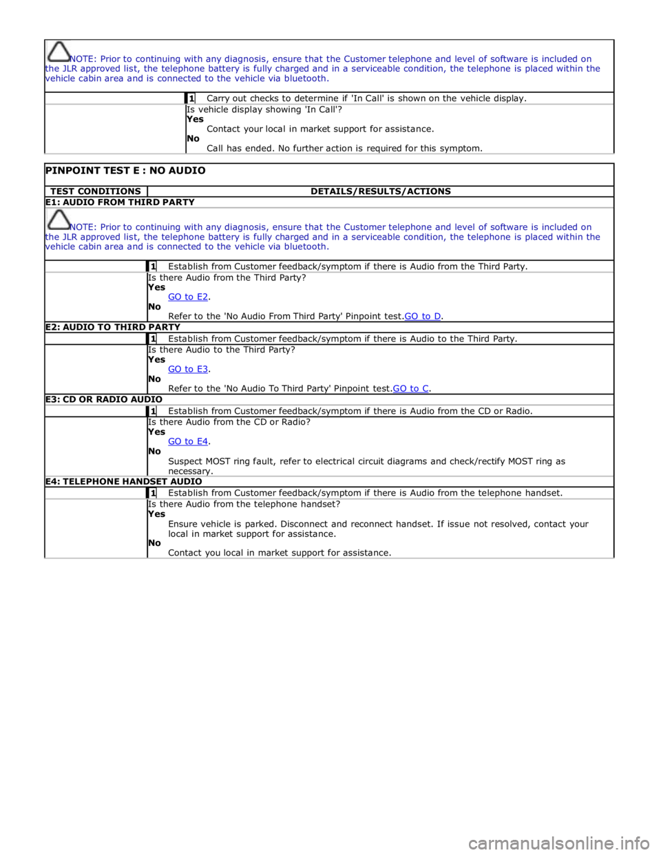
PINPOINT TEST E : NO AUDIO TEST CONDITIONS DETAILS/RESULTS/ACTIONS E1: AUDIO FROM THIRD PARTY
NOTE: Prior to continuing with any diagnosis, ensure that the Customer telephone and level of software is included on
the JLR approved list, the telephone battery is fully charged and in a serviceable condition, the telephone is placed within the
vehicle cabin area and is connected to the vehicle via bluetooth. 1 Establish from Customer feedback/symptom if there is Audio from the Third Party. Is there Audio from the Third Party? Yes
GO to E2. No
Refer to the 'No Audio From Third Party' Pinpoint test.GO to D. E2: AUDIO TO THIRD PARTY 1 Establish from Customer feedback/symptom if there is Audio to the Third Party. Is there Audio to the Third Party? Yes
GO to E3. No
Refer to the 'No Audio To Third Party' Pinpoint test.GO to C. E3: CD OR RADIO AUDIO 1 Establish from Customer feedback/symptom if there is Audio from the CD or Radio. Is there Audio from the CD or Radio? Yes
GO to E4. No
Suspect MOST ring fault, refer to electrical circuit diagrams and check/rectify MOST ring as necessary. E4: TELEPHONE HANDSET AUDIO 1 Establish from Customer feedback/symptom if there is Audio from the telephone handset. Is there Audio from the telephone handset? Yes
Ensure vehicle is parked. Disconnect and reconnect handset. If issue not resolved, contact your
local in market support for assistance.
No
Contact you local in market support for assistance.
Page 1940 of 3039
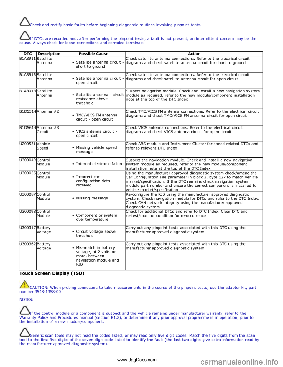
Check and rectify basic faults before beginning diagnostic routines involving pinpoint tests.
If DTCs are recorded and, after performing the pinpoint tests, a fault is not present, an intermittent concern may be the
cause. Always check for loose connections and corroded terminals.
DTC Description Possible Cause Action B1A8911
Satellite
Antenna
Satellite antenna circuit -
short to ground Check satellite antenna connections. Refer to the electrical circuit
diagrams and check satellite antenna circuit for short to ground B1A8913
Satellite
Antenna
Satellite antenna circuit -
open circuit Check satellite antenna connections. Refer to the electrical circuit
diagrams and check satellite antenna circuit for open circuit B1A891B
Satellite
Antenna
Satellite antenna - circuit
resistance above
threshold Suspect navigation module. Check and install a new navigation system
module as required, refer to the new module/component installation
note at the top of the DTC Index B1D5514 Antenna #2
TMC/VICS FM antenna
circuit - open circuit Check TMC/VICS FM antenna connections. Refer to the electrical circuit
diagrams and check TMC/VICS FM antenna circuit for open circuit B1D5614
Antenna #3
Circuit
VICS antenna circuit -
open circuit Check VICS antenna connections. Refer to the electrical circuit
diagrams and check VICS antenna circuit for open circuit U200531
Vehicle
Speed
Missing vehicle speed
message Check ABS module and Instrument Cluster for speed related DTCs and
refer to relevant DTC Index U300049
Control
Module
Internal electronic failure Suspect the navigation module. Check and install a new navigation
system module as required, refer to the new module/component
installation note at the top of the DTC Index U300055
Control
Module
Incorrect car
configuration data
received Using the manufacturer approved diagnostic system check/amend the
Car Configuration File parameter in block 2, byte 127 to match vehicle
market/specification. If the DTC remains check navigation system
module part number and ensure the correct component is installed to
vehicle market/specification U300087
Control
Module
Missing message Re-configure the RJB using the manufacturer approved diagnostic
system. Check navigation module for DTCs and refer to the DTC Index.
Check CAN network integrity using the manufacturer approved diagnostic system U300098
Control
Module
Component or system
over temperature Check for additional DTCs and refer to DTC Index. Clear DTC and
re-test/monitor condition for re-occurrence U300317
Battery
Voltage
Circuit voltage above
threshold Carry out any pinpoint tests associated with this DTC using the
manufacturer approved diagnostic system U300362
Battery
Voltage
Mis-match in battery
voltage, of 2 volts or
more, between
navigation module and
RJB Carry out any pinpoint tests associated with this DTC using the
manufacturer approved diagnostic system Touch Screen Display (TSD)
CAUTION: When probing connectors to take measurements in the course of the pinpoint tests, use the adaptor kit, part
number 3548-1358-00
NOTES:
If the control module or a component is suspect and the vehicle remains under manufacturer warranty, refer to the
Warranty Policy and Procedures manual (section B1.2), or determine if any prior approval programme is in operation, prior to
the installation of a new module/component.
Generic scan tools may not read the codes listed, or may read only five digit codes. Match the five digits from the scan
tool to the first five digits of the seven digit code listed to identify the fault (the last two digits give extra information read by
the manufacturer-approved diagnostic system).
www.JagDocs.com
Page 1941 of 3039
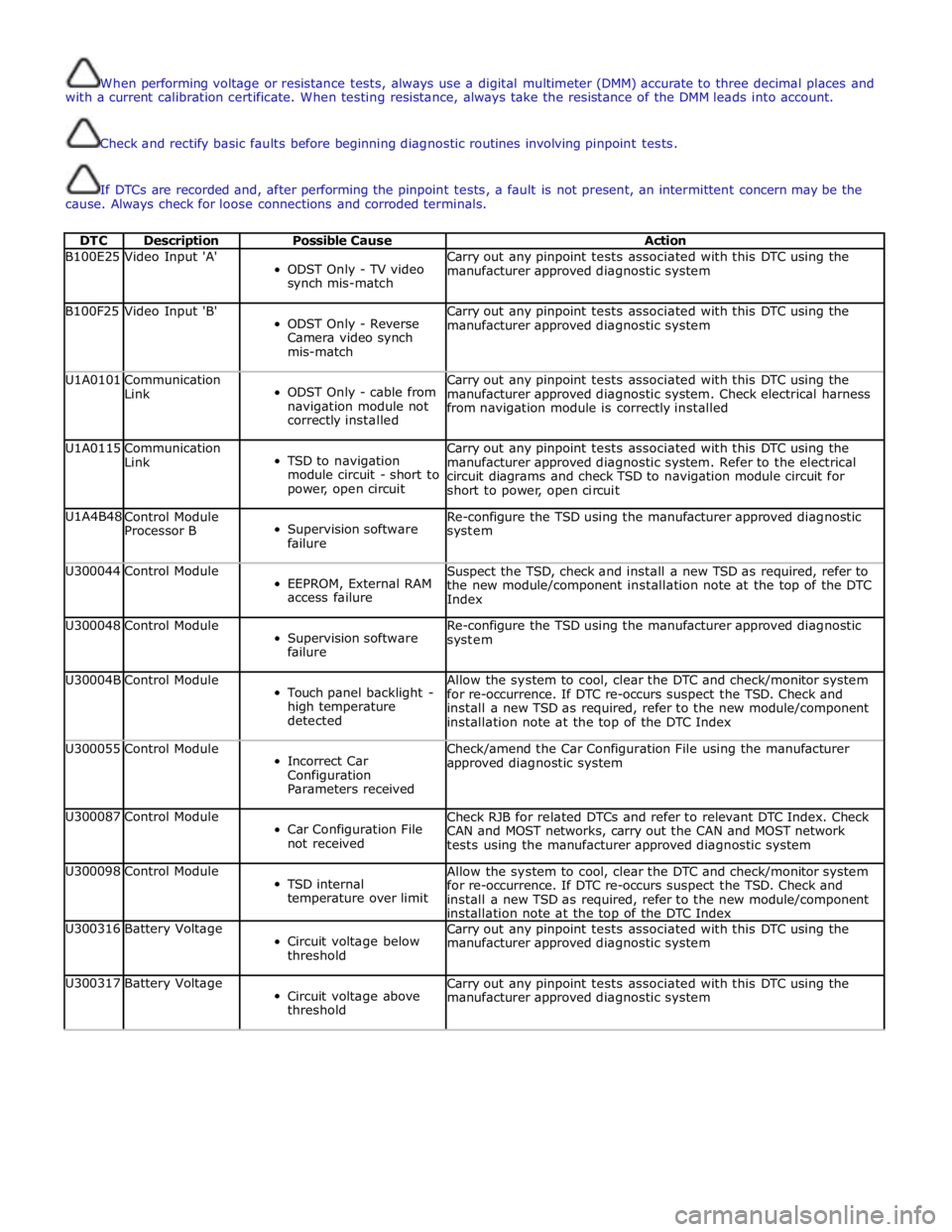
When performing voltage or resistance tests, always use a digital multimeter (DMM) accurate to three decimal places and
with a current calibration certificate. When testing resistance, always take the resistance of the DMM leads into account.
Check and rectify basic faults before beginning diagnostic routines involving pinpoint tests.
If DTCs are recorded and, after performing the pinpoint tests, a fault is not present, an intermittent concern may be the
cause. Always check for loose connections and corroded terminals.
DTC Description Possible Cause Action B100E25 Video Input 'A'
ODST Only - TV video
synch mis-match Carry out any pinpoint tests associated with this DTC using the
manufacturer approved diagnostic system B100F25 Video Input 'B'
ODST Only - Reverse
Camera video synch
mis-match Carry out any pinpoint tests associated with this DTC using the
manufacturer approved diagnostic system U1A0101
Communication
Link
ODST Only - cable from
navigation module not
correctly installed Carry out any pinpoint tests associated with this DTC using the
manufacturer approved diagnostic system. Check electrical harness
from navigation module is correctly installed U1A0115
Communication
Link
TSD to navigation
module circuit - short to
power, open circuit Carry out any pinpoint tests associated with this DTC using the
manufacturer approved diagnostic system. Refer to the electrical
circuit diagrams and check TSD to navigation module circuit for
short to power, open circuit U1A4B48
Control Module
Processor B
Supervision software
failure Re-configure the TSD using the manufacturer approved diagnostic
system U300044 Control Module
EEPROM, External RAM
access failure Suspect the TSD, check and install a new TSD as required, refer to
the new module/component installation note at the top of the DTC
Index U300048 Control Module
Supervision software
failure Re-configure the TSD using the manufacturer approved diagnostic
system U30004B Control Module
Touch panel backlight -
high temperature
detected Allow the system to cool, clear the DTC and check/monitor system
for re-occurrence. If DTC re-occurs suspect the TSD. Check and
install a new TSD as required, refer to the new module/component
installation note at the top of the DTC Index U300055 Control Module
Incorrect Car
Configuration
Parameters received Check/amend the Car Configuration File using the manufacturer
approved diagnostic system U300087 Control Module
Car Configuration File
not received Check RJB for related DTCs and refer to relevant DTC Index. Check
CAN and MOST networks, carry out the CAN and MOST network
tests using the manufacturer approved diagnostic system U300098 Control Module
TSD internal
temperature over limit Allow the system to cool, clear the DTC and check/monitor system
for re-occurrence. If DTC re-occurs suspect the TSD. Check and
install a new TSD as required, refer to the new module/component
installation note at the top of the DTC Index U300316 Battery Voltage
Circuit voltage below
threshold Carry out any pinpoint tests associated with this DTC using the
manufacturer approved diagnostic system U300317 Battery Voltage
Circuit voltage above
threshold Carry out any pinpoint tests associated with this DTC using the
manufacturer approved diagnostic system
Page 1946 of 3039
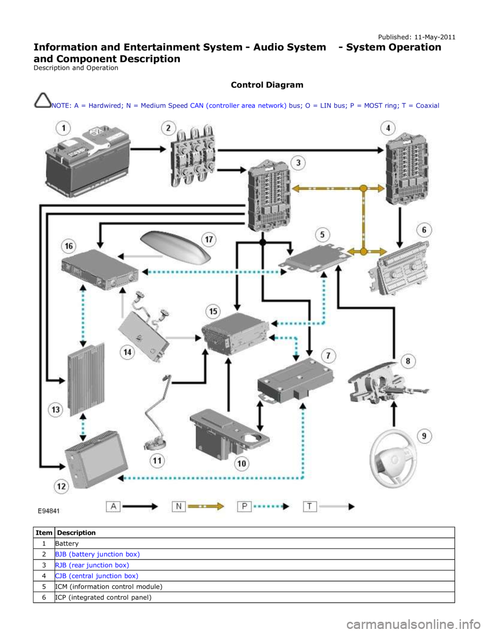
Published: 11-May-2011
Information and Entertainment System - Audio System - System Operation
and Component Description
Description and Operation
Control Diagram
NOTE: A = Hardwired; N = Medium Speed CAN (controller area network) bus; O = LIN bus; P = MOST ring; T = Coaxial
Item Description 1 Battery 2 BJB (battery junction box) 3 RJB (rear junction box) 4 CJB (central junction box) 5 ICM (information control module) 6 ICP (integrated control panel)
Page 1961 of 3039
1
2
3
4
5
6
7
8
9
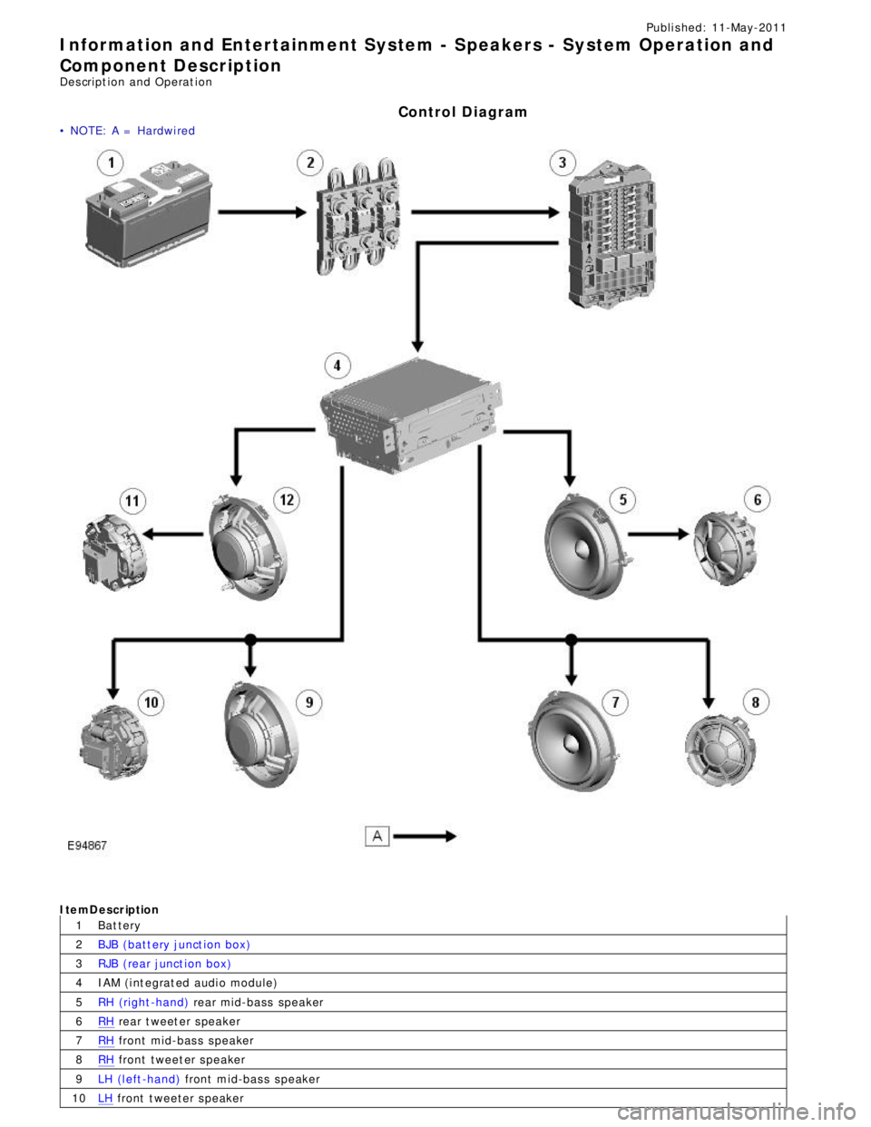
10Publi s hed: 11-May-2011
Information and Entertainment System - Speakers - System Operation and
Component Description
Des cript ion and Operat ion
Control Diagram
• NOTE: A = Hardwi red
CONTROL DIAGRAM - JAGUAR SOUND SY STEMItemDescription
Bat tery
BJB (batt ery junct ion box)
RJB (rear junct ion box)
IAM (i nt egrat ed audi o module)
RH (right -hand) rear mid-bass speakerRH rear t weet er s peakerRH front mid-bas s s peakerRH front tweet er s peaker
LH (l eft -hand) front mid-bas s s peakerLH front t weeter s peaker