2010 JAGUAR XFR diagram
[x] Cancel search: diagramPage 1686 of 3039
Published: 11-May-2011
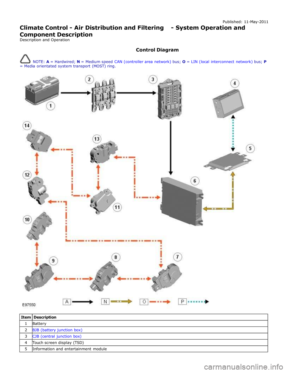
Climate Control - Air Distribution and Filtering - System Operation and
Component Description
Description and Operation
Control Diagram
NOTE: A = Hardwired; N = Medium speed CAN (controller area network) bus; O = LIN (local interconnect network) bus; P
= Media orientated system transport (MOST) ring.
Item Description 1 Battery 2 BJB (battery junction box) 3 CJB (central junction box) 4 Touch screen display (TSD) 5 Information and entertainment module
Page 1692 of 3039
Published: 11-May-2011
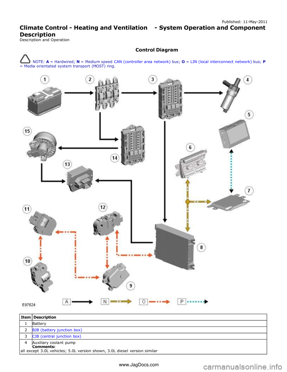
Climate Control - Heating and Ventilation - System Operation and Component Description
Description and Operation
Control Diagram
NOTE: A = Hardwired; N = Medium speed CAN (controller area network) bus; O = LIN (local interconnect network) bus; P
= Media orientated system transport (MOST) ring.
Item Description 1 Battery 2 BJB (battery junction box) 3 CJB (central junction box) 4 Auxiliary coolant pump Comments:
all except 3.0L vehicles; 5.0L version shown, 3.0L diesel version similar www.JagDocs.com
Page 1708 of 3039
Published: 11-May-2011
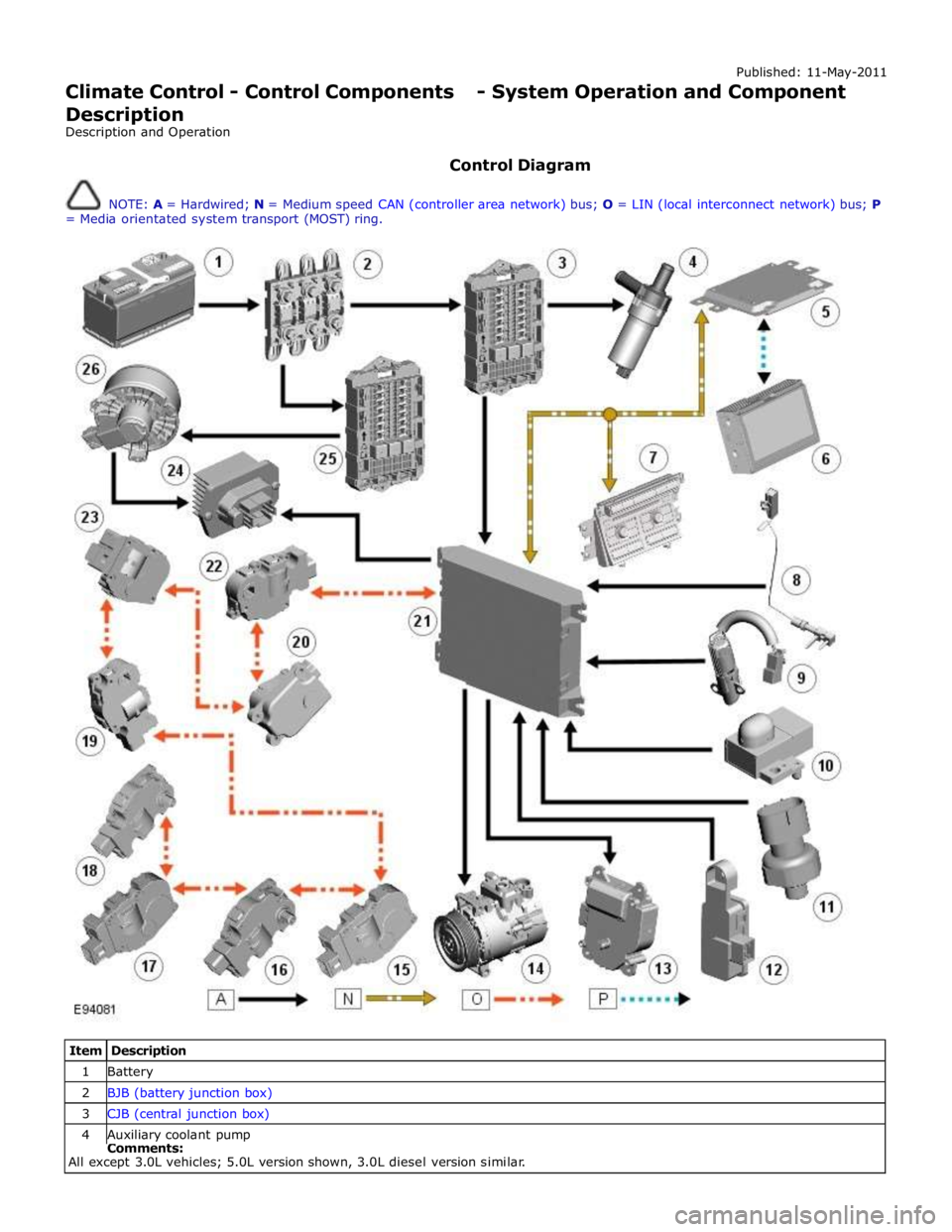
Climate Control - Control Components - System Operation and Component Description
Description and Operation
Control Diagram
NOTE: A = Hardwired; N = Medium speed CAN (controller area network) bus; O = LIN (local interconnect network) bus; P
= Media orientated system transport (MOST) ring.
Item Description 1 Battery 2 BJB (battery junction box) 3 CJB (central junction box) 4 Auxiliary coolant pump Comments:
All except 3.0L vehicles; 5.0L version shown, 3.0L diesel version similar.
Page 1766 of 3039
Published: 11-May-2011
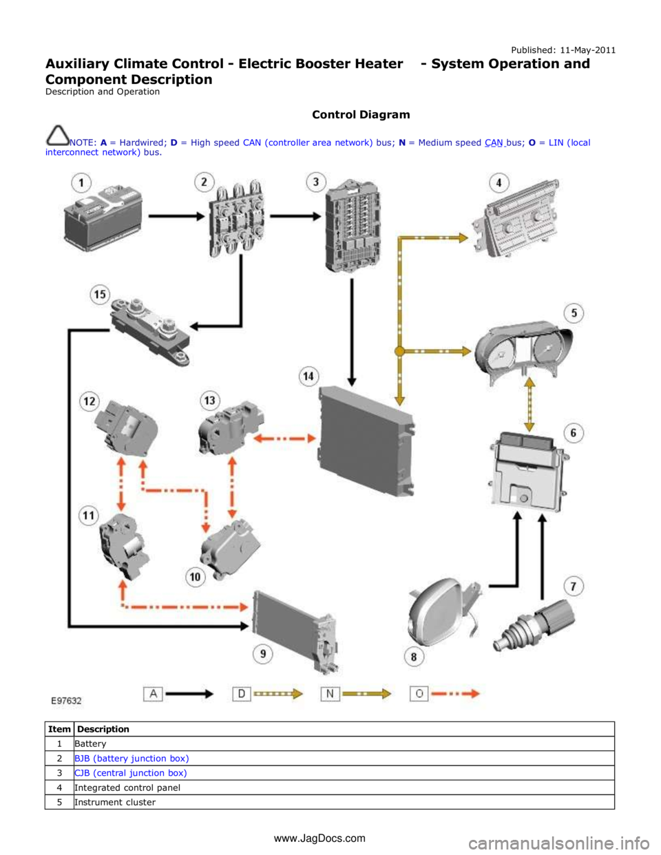
Auxiliary Climate Control - Electric Booster Heater - System Operation and
Component Description
Description and Operation
Control Diagram
NOTE: A = Hardwired; D = High speed CAN (controller area network) bus; N = Medium speed CAN bus; O = LIN (local interconnect network) bus.
Item Description 1 Battery 2 BJB (battery junction box) 3 CJB (central junction box) 4 Integrated control panel 5 Instrument cluster www.JagDocs.com
Page 1783 of 3039
Published: 11-May-2011
Instrument Cluster - Instrument Cluster - System Operation and Component Description
Description and Operation
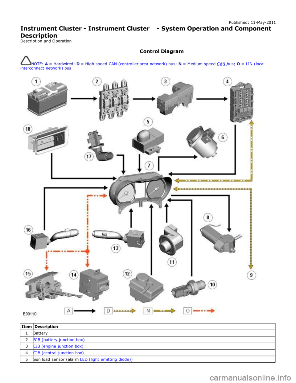
Control Diagram
NOTE: A = Hardwired; D = High speed CAN (controller area network) bus; N = Medium speed CAN bus; O = LIN (local interconnect network) bus
Item Description 1 Battery 2 BJB (battery junction box) 3 EJB (engine junction box) 4 CJB (central junction box) 5 Sun load sensor (alarm LED (light emitting diode))
Page 1791 of 3039
Instrument Cluster - Instrument Cluster
Diagnosis and Testing
Principles of Operation Published: 22-Mar-2013
For a detailed description of the Instrument Cluster, refer to the relevant Description and Operation sections in the workshop
manual. REFER to: (413-01 Instrument Cluster)
Instrument Cluster (Description and Operation), Instrument Cluster (Description and Operation), Instrument Cluster (Description and Operation).
Inspection and Verification
CAUTION: Diagnosis by substitution from a donor vehicle is NOT acceptable. Substitution of control modules does not
guarantee confirmation of a fault, and may also cause additional faults in the vehicle being tested and/or the donor vehicle.
1. Verify the customer concern.
2. Visually inspect for obvious signs of damage and system integrity.
Visual Inspection
Mechanical Electrical
Fluid level(s)
Accessory installations
Fuse(s)
Wiring harness
Electrical connector(s)
Instrument cluster
Central Junction Box (CJB)
Engine Junction Box (EJB)
Driver Door Module (DDM)
Engine Control Module (ECM)
3. If an obvious cause for an observed or reported concern is found, correct the cause (if possible) before proceeding to
the next step.
4. If the cause is not visually evident, verify the symptom and refer to the Symptom Chart.
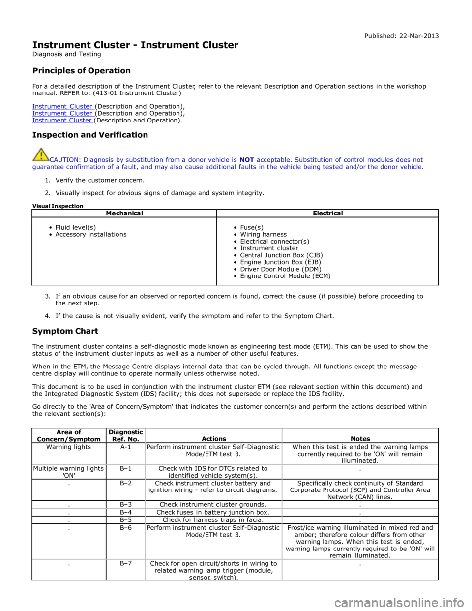
Symptom Chart
The instrument cluster contains a self-diagnostic mode known as engineering test mode (ETM). This can be used to show the
status of the instrument cluster inputs as well as a number of other useful features.
When in the ETM, the Message Centre displays internal data that can be cycled through. All functions except the message
centre display will continue to operate normally unless otherwise noted.
This document is to be used in conjunction with the instrument cluster ETM (see relevant section within this document) and
the Integrated Diagnostic System (IDS) facility; this does not supersede or replace the IDS facility.
Go directly to the 'Area of Concern/Symptom' that indicates the customer concern(s) and perform the actions described within
the relevant section(s):
Area of Concern/Symptom Diagnostic
Ref. No.
Actions
Notes Warning lights A-1
Perform instrument cluster Self-Diagnostic
Mode/ETM test 3. When this test is ended the warning lamps
currently required to be 'ON' will remain
illuminated. Multiple warning lights
'ON' B–1
Check with IDS for DTCs related to
identified vehicle system(s). . . B–2
Check instrument cluster battery and
ignition wiring - refer to circuit diagrams. Specifically check continuity of Standard
Corporate Protocol (SCP) and Controller Area
Network (CAN) lines. . B–3 Check instrument cluster grounds. . . B–4 Check fuses in battery junction box. . . B–5 Check for harness traps in facia. . . B–6
Perform instrument cluster Self-Diagnostic
Mode/ETM test 3. Frost/ice warning illuminated in mixed red and
amber; therefore colour differs from other
warning lamps. When this test is ended,
warning lamps currently required to be 'ON' will
remain illuminated. . B–7
Check for open circuit/shorts in wiring to
related warning lamp trigger (module,
sensor, switch). .
Page 1797 of 3039
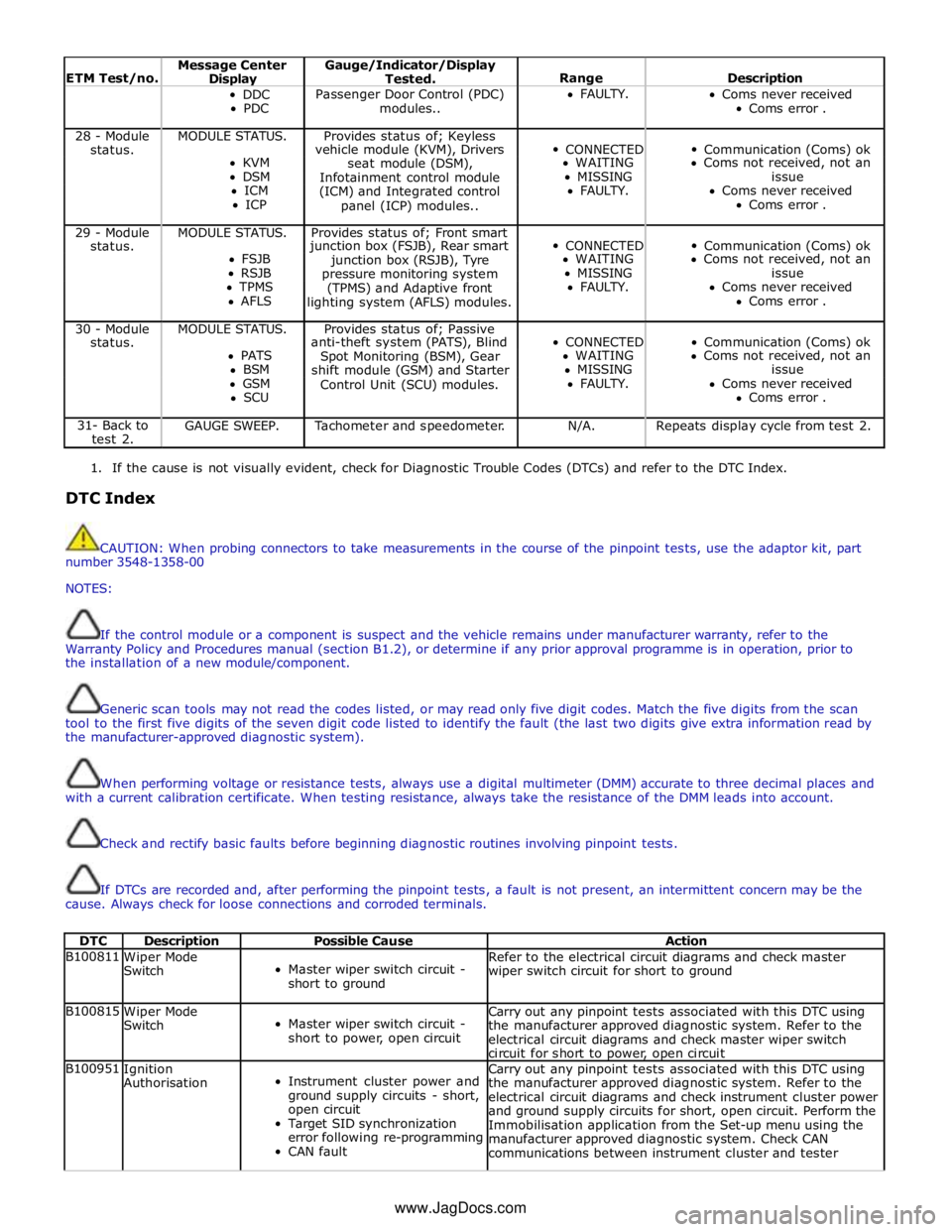
ETM Test/no. Message Center Display Gauge/Indicator/Display
Tested.
Range
Description DDC
PDC Passenger Door Control (PDC)
modules.. FAULTY.
Coms never received
Coms error . 28 - Module MODULE STATUS. Provides status of; Keyless
CONNECTED
Communication (Coms) ok status. vehicle module (KVM), Drivers KVM
seat module (DSM), WAITING Coms not received, not an DSM
Infotainment control module MISSING issue ICM
(ICM) and Integrated control FAULTY. Coms never received ICP
panel (ICP) modules.. Coms error . 29 - Module MODULE STATUS. Provides status of; Front smart
CONNECTED
Communication (Coms) ok status. junction box (FSJB), Rear smart FSJB
junction box (RSJB), Tyre WAITING Coms not received, not an RSJB
pressure monitoring system MISSING issue TPMS
(TPMS) and Adaptive front FAULTY. Coms never received AFLS
lighting system (AFLS) modules. Coms error . 30 - Module MODULE STATUS. Provides status of; Passive
CONNECTED
Communication (Coms) ok status. anti-theft system (PATS), Blind PATS
Spot Monitoring (BSM), Gear WAITING Coms not received, not an BSM
shift module (GSM) and Starter MISSING issue GSM
Control Unit (SCU) modules. FAULTY. Coms never received SCU Coms error . 31- Back to
test 2. GAUGE SWEEP. Tachometer and speedometer. N/A. Repeats display cycle from test 2.
1. If the cause is not visually evident, check for Diagnostic Trouble Codes (DTCs) and refer to the DTC Index.
DTC Index
CAUTION: When probing connectors to take measurements in the course of the pinpoint tests, use the adaptor kit, part
number 3548-1358-00
NOTES:
If the control module or a component is suspect and the vehicle remains under manufacturer warranty, refer to the
Warranty Policy and Procedures manual (section B1.2), or determine if any prior approval programme is in operation, prior to
the installation of a new module/component.
Generic scan tools may not read the codes listed, or may read only five digit codes. Match the five digits from the scan
tool to the first five digits of the seven digit code listed to identify the fault (the last two digits give extra information read by
the manufacturer-approved diagnostic system).
When performing voltage or resistance tests, always use a digital multimeter (DMM) accurate to three decimal places and
with a current calibration certificate. When testing resistance, always take the resistance of the DMM leads into account.
Check and rectify basic faults before beginning diagnostic routines involving pinpoint tests.
If DTCs are recorded and, after performing the pinpoint tests, a fault is not present, an intermittent concern may be the
cause. Always check for loose connections and corroded terminals.
DTC Description Possible Cause Action B100811
Wiper Mode
Switch
Master wiper switch circuit -
short to ground Refer to the electrical circuit diagrams and check master
wiper switch circuit for short to ground B100815
Wiper Mode
Switch
Master wiper switch circuit -
short to power, open circuit Carry out any pinpoint tests associated with this DTC using
the manufacturer approved diagnostic system. Refer to the
electrical circuit diagrams and check master wiper switch
circuit for short to power, open circuit B100951
Ignition
Authorisation
Instrument cluster power and
ground supply circuits - short,
open circuit
Target SID synchronization
error following re-programming
CAN fault Carry out any pinpoint tests associated with this DTC using
the manufacturer approved diagnostic system. Refer to the
electrical circuit diagrams and check instrument cluster power
and ground supply circuits for short, open circuit. Perform the
Immobilisation application from the Set-up menu using the
manufacturer approved diagnostic system. Check CAN
communications between instrument cluster and tester www.JagDocs.com
Page 1798 of 3039

DTC Description Possible Cause Action B100962
Ignition
Authorisation
LS CAN fault
CJB ignition, power and
ground supply circuits - short,
open circuit
Instrument cluster power and
ground supply circuits - short,
open circuit
Incorrect CJB or instrument
cluster installed
Target SID synchronization
error following re-programming
Noise/EMC related error Carry out any pinpoint tests associated with this DTC using
the manufacturer approved diagnostic system. Check CAN
communications between CJB and instrument cluster. Refer
to the electrical circuit diagrams and check CJB ignition,
power and ground supply circuits for short, open circuit and
instrument cluster power and ground supply circuits for short,
open circuit. Check correct CJB and instrument cluster
installed. Perform the Immobilisation application from the
Set-up menu using the manufacturer approved diagnostic
system. Check CAN network for interference/EMC related
issues B100987
Ignition
Authorisation
CJB ignition, power and
ground supply circuits - short,
open circuit
LS CAN fault
Instrument cluster power and
ground supply circuits - short,
open circuit
Low battery voltage <9 volts Carry out any pinpoint tests associated with this DTC using
the manufacturer approved diagnostic system. Refer to the
electrical circuit diagrams and check CJB ignition, power and
ground supply circuits for short, open circuit and instrument
cluster power and ground supply circuits for short, open
circuit. Check CAN communications between CJB and
instrument cluster. Check battery is in serviceable condition
and fully charged B100A62
Fuel Pump
Authorisation
LS CAN fault
RJB power and ground supply
circuits - short, open circuit
Instrument cluster power and
ground supply circuits - short,
open circuit
Incorrect RJB or instrument
cluster installed
Target SID synchronization
error following re-programming
Noise/EMC related error Carry out any pinpoint tests associated with this DTC using
the manufacturer approved diagnostic system. Check CAN
communications between RJB and instrument cluster. Refer
to the electrical circuit diagrams and check RJB power and
ground supply circuits for short, open circuit and instrument
cluster power and ground supply circuits for short, open
circuit. Check correct RJB and instrument cluster installed.
Perform the Immobilisation application from the Set-up menu
using the manufacturer approved diagnostic system. Check
CAN network for interference/EMC related issues B100A64
Fuel Pump
Authorisation
Target SID synchronization
error following re-programming
RJB power and ground supply
circuits - short, open circuit
LS CAN fault Carry out any pinpoint tests associated with this DTC using
the manufacturer approved diagnostic system. Perform the
Immobilisation application from the Set-up menu using the
manufacturer approved diagnostic system. Refer to the
electrical circuit diagrams and check RJB power and ground
supply circuits for short, open circuit. Check CAN
communications between RJB and instrument cluster B100A87
Fuel Pump
Authorisation
RJB power and ground supply
circuits - short, open circuit
LS CAN fault
Instrument cluster power and
ground supply circuits - short,
open circuit
Low battery voltage <9 volts Carry out any pinpoint tests associated with this DTC using
the manufacturer approved diagnostic system. Refer to the
electrical circuit diagrams and check RJB power and ground
supply circuits for short, open circuit and instrument cluster
power and ground supply circuits for short, open circuit.
Check CAN communications between RJB and instrument
cluster. Check battery is in serviceable condition and fully
charged B100B67
Column Lock
Ground
Authorisation
Algorithm based failure-signal
is incorrect after the event
Instrument cluster power and
ground supply circuits - short,
open circuit
LS CAN fault
RJB power and ground supply
circuits - short, open circuit
Vehicle speed present when
attempting to power ESCL
Engine speed present when
attempting to power ESCL
PowerMode status > 4 when
attempting to perform lock
action If a non start issue has not been identified, clear the DTC
and check vehicle starts correctly. If a non start issue has
been identified run the manufacturers approved diagnostic
system Start Authorisation Application. Carry out any
pinpoint tests associated with this DTC using the
manufacturer approved diagnostic system. Refer to the
electrical circuit diagrams and check RJB power and ground
supply circuits for short, open circuit and instrument cluster
power and ground supply circuits for short, open circuit.
Check CAN communications between RJB and instrument
cluster. Check for invalid vehicle speed signal from
ABS/instrument cluster gateway. Check for invalid engine
speed signal from ECM/instrument cluster gateway. Check for
invalid signal from CJB B100B87
Column Lock
Ground
Authorisation
Instrument cluster power and
ground supply circuits - short,
open circuit
LS CAN fault
RJB power and ground supply
circuits - short, open circuit Carry out any pinpoint tests associated with this DTC using
the manufacturer approved diagnostic system. Refer to the
electrical circuit diagrams and check RJB power and ground
supply circuits for short, open circuit and instrument cluster
power and ground supply circuits for short, open circuit.
Check CAN communications between RJB and instrument
cluster