2010 JAGUAR XFR purge valve
[x] Cancel search: purge valvePage 1370 of 3039

Symptom Possible Cause Action (EGR) valve stuck open
Fuel pump
Evaporative emissions purge
valve care manual and the relevant sections of the
workshop manual.
Read DTCs and refer to DTC Index in this
section for electronic engine control tests
Refer to the relevant section of the
workshop manual and check the Exhaust Gas
Recirculation (EGR) valve and associated
hoses and connections.
For fuel system tests refer to the relevant
section of the workshop manual
Refer to the relevant section of the
workshop manual and check the purge valve
and associated hoses and connections. Difficult hot start
Injector leak
Electronic engine controls
Evaporative emissions purge
valve
Fuel pump
Ignition system
EGR valve stuck open
Refer to the relevant section of the
workshop manual, carry out injector leak
tests, install new injectors as necessary.
Read DTCs and refer to DTC Index in this
section for electronic engine control tests
Refer to the relevant section of the
workshop manual and check the purge valve
and associated hoses and connections.
For fuel system tests refer to the relevant
section of the workshop manual
For ignition system tests refer to the
relevant section of the workshop manual
Refer to the relevant section of the
workshop manual and check the Exhaust Gas
Recirculation (EGR) valve and associated
hoses and connections. Difficult to start after hot soak
(vehicle standing, engine off, after
engine has reached operating
temperature)
Injector leak
Electronic engine controls
Evaporative emissions purge
valve
Fuel pump
Ignition system
EGR valve stuck open
Refer to the relevant section of the
workshop manual, carry out injector leak
tests, install new injectors as necessary.
Read DTCs and refer to DTC Index in this
section for electronic engine control tests
Refer to the relevant section of the
workshop manual and check the purge valve
and associated hoses and connections.
For fuel system tests refer to the relevant
section of the workshop manual
For ignition system tests refer to the
relevant section of the workshop manual
Refer to the relevant section of the
workshop manual and check the Exhaust Gas
Recirculation (EGR) valve and associated
hoses and connections. Engine cranks too fast/slow
Compressions high/low
Battery
Starting system
Refer to the relevant section of the
workshop manual, carry out compression
tests.
Ensure the battery is in a fully charged and
serviceable condition. Refer to the battery
care manual and the relevant sections of the
workshop manual.
For starting system tests refer to the
relevant section of the workshop manual Engine stalls Engine stalls soon after start
Breather system
disconnected/restricted
ECM relay
Electronic engine controls
Ignition system
Air intake system restricted
Air leakage
Fuel lines
Ensure the engine breather system is free
from restriction and is correctly installed
Read DTCs and refer to DTC Index in this
section for ECM relay tests
Read DTCs and refer to DTC Index in this
section for electronic engine control tests
For ignition system tests refer to the
relevant section of the workshop manual
Check for blockage in air cleaner element
and air intake system
Check for leakage in air intake system
For fuel system tests refer to the relevant
section of the workshop manual
Page 1582 of 3039

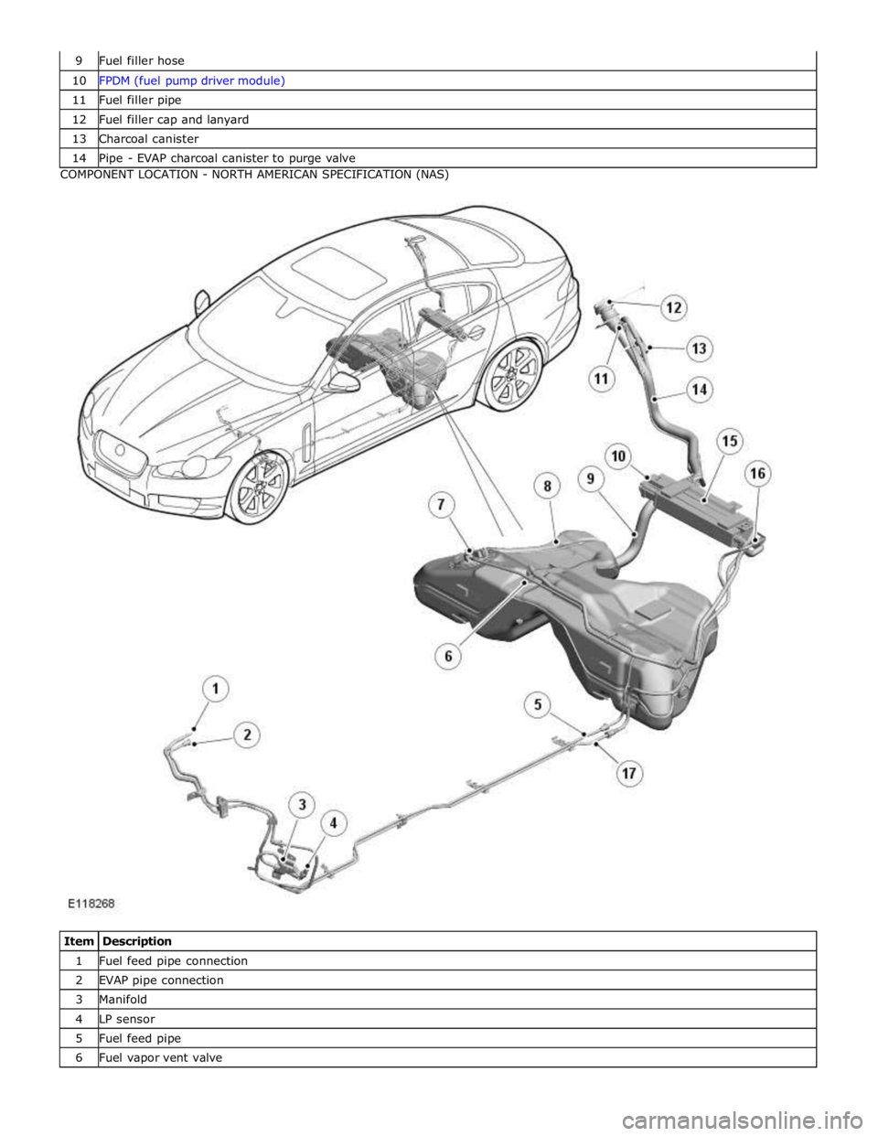
10 FPDM (fuel pump driver module) 11 Fuel filler pipe 12 Fuel filler cap and lanyard 13 Charcoal canister 14 Pipe - EVAP charcoal canister to purge valve COMPONENT LOCATION - NORTH AMERICAN SPECIFICATION (NAS)
Item Description 1 Fuel feed pipe connection 2 EVAP pipe connection 3 Manifold 4 LP sensor 5 Fuel feed pipe 6 Fuel vapor vent valve
Page 1583 of 3039

8 Fuel tank 9 Fuel filler hose 10 FPDM 11 Anti-trickle valve 12 Fuel filler cap and lanyard 13 DMTL filter 14 Fuel filler pipe 15 Charcoal canister 16 DMTL pump 17 Pipe - EVAP charcoal canister to purge valve
Page 1586 of 3039

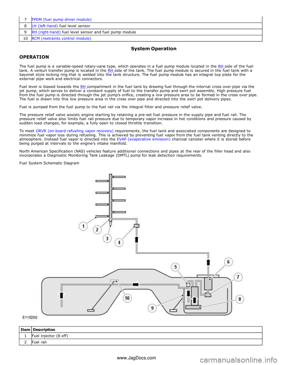
8 LH (left-hand) fuel level sensor 9 RH (right-hand) fuel level sensor and fuel pump module 10 RCM (restraints control module)
OPERATION System Operation
The fuel pump is a variable-speed rotary-vane type, which operates in a fuel pump module located in the RH side of the fuel tank. A venturi transfer pump is located in the RH side of the tank. The fuel pump module is secured in the fuel tank with a bayonet style locking ring that is welded into the tank structure. The fuel pump module has an integral top plate for the
external pipe work and electrical connectors.
Fuel level is biased towards the RH compartment in the fuel tank by drawing fuel through the internal cross over pipe via the jet pump, which serves to deliver a constant supply of fuel to the transfer pump and swirl pot assembly. High pressure fuel
from the fuel pump is directed through the jet pump's orifice, creating a low pressure area to be formed in the cross over pipe.
The fuel is drawn into this low pressure area in the cross over pipe and directed into the swirl pot delivery pipes.
Fuel is pumped from the fuel pump to the fuel rail via the integral filter and pressure relief valve.
The pressure relief valve assists engine starting by retaining a pre-set fuel pressure in the supply pipe and fuel rail. The
pressure relief valve also limits fuel rail pressure due to temporary vapor increase in hot conditions and pressure caused by
sudden load changes, for example, a fully open to closed throttle transition.
To meet ORVR (on-board refueling vapor recovery) requirements, the fuel tank and associated components are designed to
minimize fuel vapor loss during refueling. This is achieved by preventing fuel vapor from the fuel tank venting directly to the
atmosphere. Instead fuel vapor is directed into the EVAP (evaporative emission) charcoal canister where it is stored before
being purged at intervals to the engine’s intake manifold.
North American Specification (NAS) vehicles feature additional connections and pipes at the rear of the filler head and also
incorporates a Diagnostic Monitoring Tank Leakage (DMTL) pump for leak detection requirements.
Fuel System Schematic Diagram
Item Description 1 Fuel injector (8 off) 2 Fuel rail www.JagDocs.com
Page 1587 of 3039

3 Fuel High Pressure (HP) sensor 4 Fuel LP sensor 5 Jet pump 6 Fuel filter 7 Pressure relief valve 8 Fuel pump module assembly 9 RH fuel level sensor 10 LH fuel level sensor
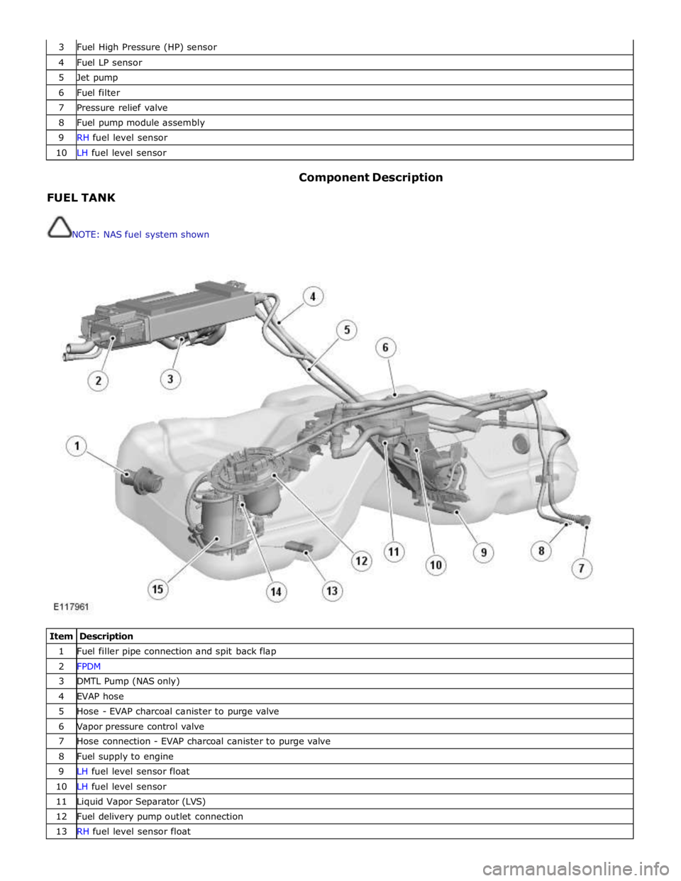
FUEL TANK
NOTE: NAS fuel system shown Component Description
Item Description 1 Fuel filler pipe connection and spit back flap 2 FPDM 3 DMTL Pump (NAS only) 4 EVAP hose 5 Hose - EVAP charcoal canister to purge valve 6 Vapor pressure control valve 7 Hose connection - EVAP charcoal canister to purge valve 8 Fuel supply to engine 9 LH fuel level sensor float 10 LH fuel level sensor 11 Liquid Vapor Separator (LVS) 12 Fuel delivery pump outlet connection 13 RH fuel level sensor float
Page 1596 of 3039

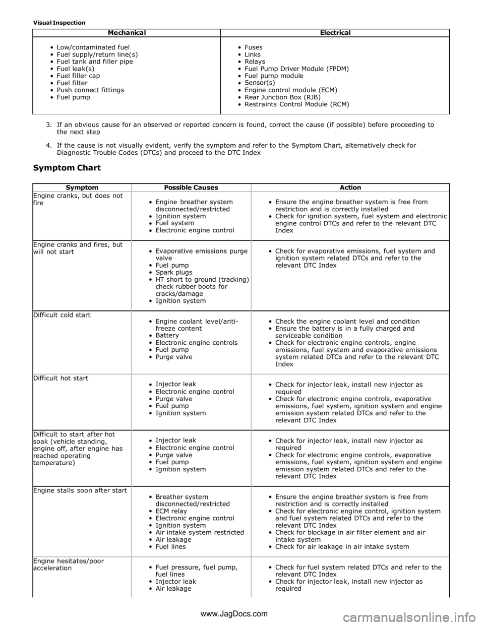
Visual Inspection
Mechanical Electrical
Low/contaminated fuel
Fuel supply/return line(s)
Fuel tank and filler pipe
Fuel leak(s)
Fuel filler cap
Fuel filter
Push connect fittings
Fuel pump
Fuses
Links
Relays
Fuel Pump Driver Module (FPDM)
Fuel pump module
Sensor(s)
Engine control module (ECM)
Rear Junction Box (RJB)
Restraints Control Module (RCM)
3. If an obvious cause for an observed or reported concern is found, correct the cause (if possible) before proceeding to
the next step
4. If the cause is not visually evident, verify the symptom and refer to the Symptom Chart, alternatively check for
Diagnostic Trouble Codes (DTCs) and proceed to the DTC Index
Symptom Chart
Symptom Possible Causes Action Engine cranks, but does not
fire
Engine breather system
disconnected/restricted
Ignition system
Fuel system
Electronic engine control
Ensure the engine breather system is free from
restriction and is correctly installed
Check for ignition system, fuel system and electronic
engine control DTCs and refer to the relevant DTC
Index Engine cranks and fires, but
will not start
Evaporative emissions purge
valve
Fuel pump
Spark plugs
HT short to ground (tracking)
check rubber boots for
cracks/damage
Ignition system
Check for evaporative emissions, fuel system and
ignition system related DTCs and refer to the
relevant DTC Index Difficult cold start
Engine coolant level/anti-
freeze content
Battery
Electronic engine controls
Fuel pump
Purge valve
Check the engine coolant level and condition
Ensure the battery is in a fully charged and
serviceable condition
Check for electronic engine controls, engine
emissions, fuel system and evaporative emissions
system related DTCs and refer to the relevant DTC
Index Difficult hot start
Injector leak
Electronic engine control
Purge valve
Fuel pump
Ignition system
Check for injector leak, install new injector as
required
Check for electronic engine controls, evaporative
emissions, fuel system, ignition system and engine
emission system related DTCs and refer to the
relevant DTC Index Difficult to start after hot
soak (vehicle standing,
engine off, after engine has
reached operating
temperature)
Injector leak
Electronic engine control
Purge valve
Fuel pump
Ignition system
Check for injector leak, install new injector as
required
Check for electronic engine controls, evaporative
emissions, fuel system, ignition system and engine
emission system related DTCs and refer to the
relevant DTC Index Engine stalls soon after start
Breather system
disconnected/restricted
ECM relay
Electronic engine control
Ignition system
Air intake system restricted
Air leakage
Fuel lines
Ensure the engine breather system is free from
restriction and is correctly installed
Check for electronic engine control, ignition system
and fuel system related DTCs and refer to the
relevant DTC Index
Check for blockage in air filter element and air
intake system
Check for air leakage in air intake system Engine hesitates/poor
acceleration
Fuel pressure, fuel pump,
fuel lines
Injector leak
Air leakage
Check for fuel system related DTCs and refer to the
relevant DTC Index
Check for injector leak, install new injector as
required www.JagDocs.com