2010 JAGUAR XFR low oil pressure
[x] Cancel search: low oil pressurePage 868 of 3039

cooling jets and the timing chain lubrication jets.
The oil returns to the oil pan under gravity. Large drain holes through the cylinder heads and cylinder block ensure the rapid
return of the oil to the sump pan. System replenishment is through the oil filler cap on the LH cylinder head cover.
An oil evacuation tube is installed to allow oil to be drawn from the sump pan. The upper end of the oil evacuation tube is
located under the oil filler cap.
An oil drain plug is installed in the RH side of the sump pan.
Oil Pump Nominal Operating Pressures
Engine Speed, rev/min Temperature, °C (°F) Pressure, bar (lbf/in2
) Idle 20 (68) 2.0 (29.0) 1500 20 (68) 6.0 (87.0) 3000 40 (104) 6.2 (90.0) 3000 110 (230) 5.0 (72.5) 3000 130 (266) 4.0 (58.0) Oil Level Monitoring
Oil level monitoring is provided by an oil level and temperature sensor that measures the oil level in the sump pan. The oil
level can be displayed in the message center of the instrument cluster.
The oil level and temperature sensor supplies the ECM with a signal containing the level and temperature of the oil in the sump pan. The oil level and temperature sensor is secured to the bottom of the sump pan with three screws and sealed with a
gasket.
The oil level and temperature sensor sends an ultrasonic pulse vertically upward and measures the time taken for the pulse to
be reflected back from the top surface of the oil. This time is compared with the time taken for an ultrasonic pulse to travel a
reference distance within the oil level and temperature sensor to determine the oil level. The oil level reading is combined with
the oil temperature reading and transmitted in a PWM signal to the ECM.
Oil Level and Temperature Sensor Specifications
Feature Details Power source Battery Voltage Level Accuracy ±2 mm (±0.08 in.) at temperatures of -30 °C (-22 °F)) and above; (±4 mm (±0.16 in.) at
temperatures below -30 °C (-22 °F)) Temperature Accuracy ±2 °C (±3.6 °F) Operating Level Range 116 to 147 mm (4.57 to 5.79 in.)
Page 1114 of 3039
14 Radiator 15 Auxiliary radiator 16 Connection with supercharger cooling system
System Operation
When the engine is running, the coolant is circulated around the engine cooling system by the coolant pump. From the coolant
pump, coolant flows through the cylinder heads and the engine oil cooler into the cylinder block and the heater manifold.
In the cylinder block, the coolant flows forwards to the outlet tube. When the coolant is cold, the thermostat is closed and the
coolant flows direct from the outlet tube back to the coolant pump. Once the coolant reaches operating temperature the
thermostat begins to open, to control system temperature, and coolant flows from the outlet tube to the coolant pump via the
radiator and, on SC (supercharger) vehicles, the auxiliary radiator. When the thermostat is open, the coolant flow through the
radiator(s) also generates a coolant flow through the transmission fluid cooler.
From the heater manifold the coolant flows through the electronic throttle and the heater core, in parallel circuits that are
unaffected by the position of the thermostat. From the electronic throttle, the coolant merges with bleed coolant from the
coolant pump and the outlet tube and flows to the expansion tank. From the heater core, the coolant flows back to the inlet of
the coolant pump.
Expansion and contraction of the coolant is accommodated by an air space in the expansion tank and the compliance of the
flexible hoses.
If the coolant level in the expansion tank decreases below a predetermined value, the level sensor connects a ground to the
instrument cluster, which activates the appropriate warning. For additional information, refer to 413-01 Instrument Cluster.
The cooling fan is operated by a fan control module integrated into the cooling fan motor. The fan control module regulates the
voltage, and thus speed, of the cooling fan motor in response to a PWM (pulse width modulation) signal from the ECM (engine
control module).
The cooling fan receives a battery feed and an ignition feed from the EJB (engine junction box). The ignition feed is supplied
from the main relay in the EJB, which is controlled by the ECM.
The ECM calculates the required fan speed from the engine temperature, A/C (air conditioning) system pressure and transmission fluid temperature. Under hot operating conditions, the fan may continue to operate for 4 minutes after the engine
has been switched off.
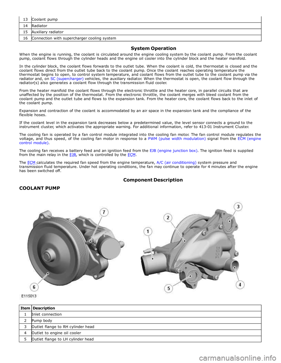
COOLANT PUMP Component Description
Item Description 1 Inlet connection 2 Pump body 3 Outlet flange to RH cylinder head 4 Outlet to engine oil cooler 5 Outlet flange to LH cylinder head
Page 1115 of 3039
7 Bleed pipe connection (containing check valve) The body of the coolant pump contains an impeller attached to a shaft supported in a bearing assembly. The impeller is driven
by a pulley, pressed on to the front of the shaft, which is driven by the accessory drive belt. For additional information, refer to
303-05E Accessory Drive - 5.0L, Vehicles Without: Supercharger or 303-05F - 5.0L, Vehicles With: Supercharger.
Two coolant outlet flanges attach the coolant pump to the front of the cylinder heads. A pipe connects a further coolant outlet
to a pipe from the engine oil cooler. A bleed connector is installed in the front of the coolant pump, adjacent to the coolant
inlet connection from the thermostat. A check valve is incorporated into the bleed connection.
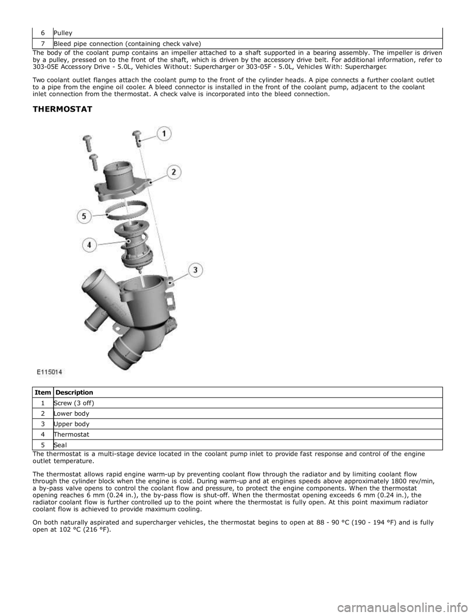
THERMOSTAT
Item Description 1 Screw (3 off) 2 Lower body 3 Upper body 4 Thermostat 5 Seal The thermostat is a multi-stage device located in the coolant pump inlet to provide fast response and control of the engine
outlet temperature.
The thermostat allows rapid engine warm-up by preventing coolant flow through the radiator and by limiting coolant flow
through the cylinder block when the engine is cold. During warm-up and at engines speeds above approximately 1800 rev/min,
a by-pass valve opens to control the coolant flow and pressure, to protect the engine components. When the thermostat
opening reaches 6 mm (0.24 in.), the by-pass flow is shut-off. When the thermostat opening exceeds 6 mm (0.24 in.), the
radiator coolant flow is further controlled up to the point where the thermostat is fully open. At this point maximum radiator
coolant flow is achieved to provide maximum cooling.
On both naturally aspirated and supercharger vehicles, the thermostat begins to open at 88 - 90 °C (190 - 194 °F) and is fully
open at 102 °C (216 °F).
Page 1177 of 3039
Fuel Charging and Controls - V8 S/C 5.0L Petrol -
WARNINGS: Published: 11-May-2011
Do not smoke or carry lighted tobacco or open flame of any type when working on or near any fuel related components.
Highly flammable vapors are always present and may ignite. Failure to follow these instructions may result in personal injury.
Before any work is carried out on the fuel system, ground the vehicle to earth and maintain the ground connection until
the work is complete.
CAUTION: Before disconnecting or removing components, make sure the area around the joint faces and connections are
clean. Plug open connections to prevent contamination.
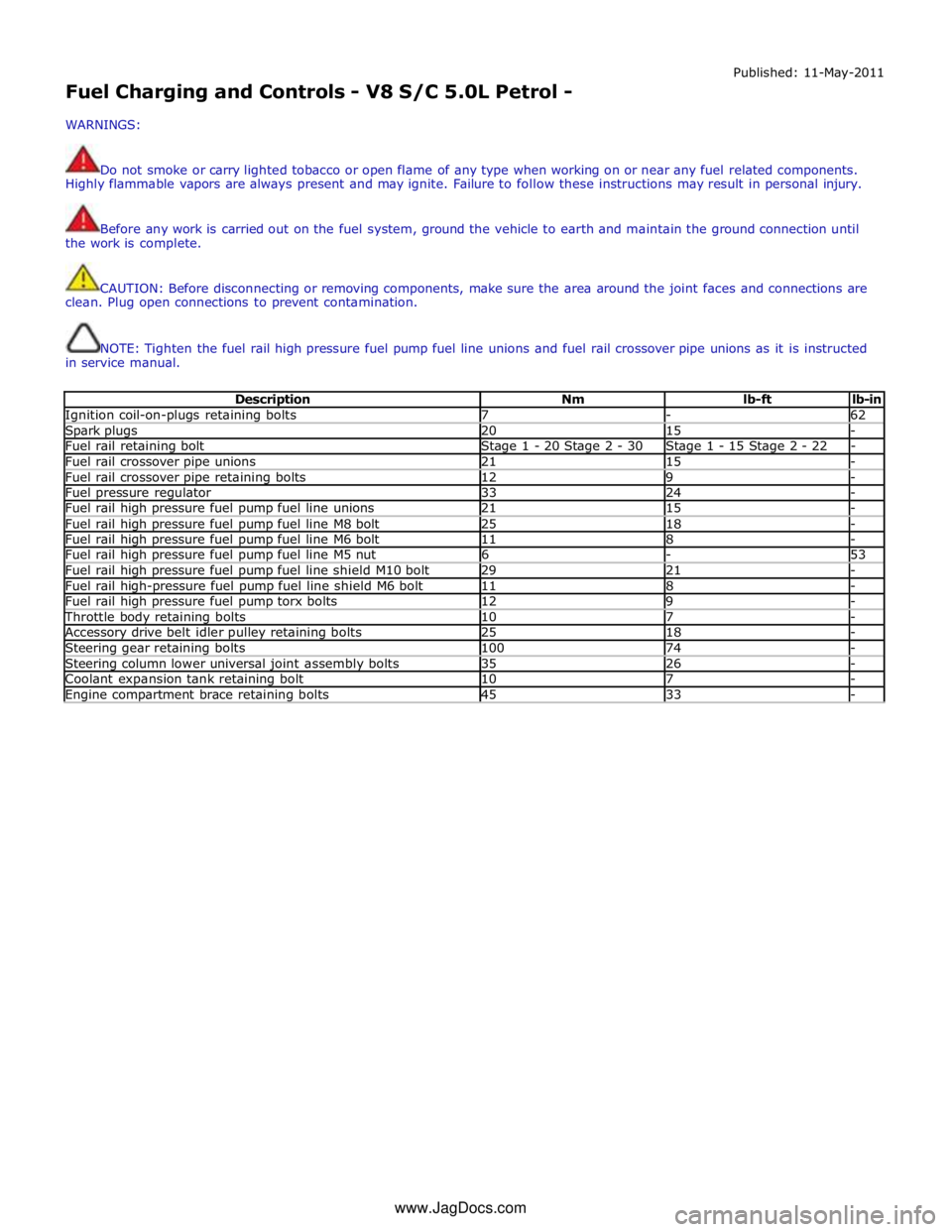
NOTE: Tighten the fuel rail high pressure fuel pump fuel line unions and fuel rail crossover pipe unions as it is instructed
in service manual.
Description Nm lb-ft lb-in Ignition coil-on-plugs retaining bolts 7 - 62 Spark plugs 20 15 - Fuel rail retaining bolt Stage 1 - 20 Stage 2 - 30 Stage 1 - 15 Stage 2 - 22 - Fuel rail crossover pipe unions 21 15 - Fuel rail crossover pipe retaining bolts 12 9 - Fuel pressure regulator 33 24 - Fuel rail high pressure fuel pump fuel line unions 21 15 - Fuel rail high pressure fuel pump fuel line M8 bolt 25 18 - Fuel rail high pressure fuel pump fuel line M6 bolt 11 8 - Fuel rail high pressure fuel pump fuel line M5 nut 6 - 53 Fuel rail high pressure fuel pump fuel line shield M10 bolt 29 21 - Fuel rail high-pressure fuel pump fuel line shield M6 bolt 11 8 - Fuel rail high pressure fuel pump torx bolts 12 9 - Throttle body retaining bolts 10 7 - Accessory drive belt idler pulley retaining bolts 25 18 - Steering gear retaining bolts 100 74 - Steering column lower universal joint assembly bolts 35 26 - Coolant expansion tank retaining bolt 10 7 - Engine compartment brace retaining bolts 45 33 - www.JagDocs.com
Page 1181 of 3039
to deliver the correct mass of fuel to the combustion chambers.
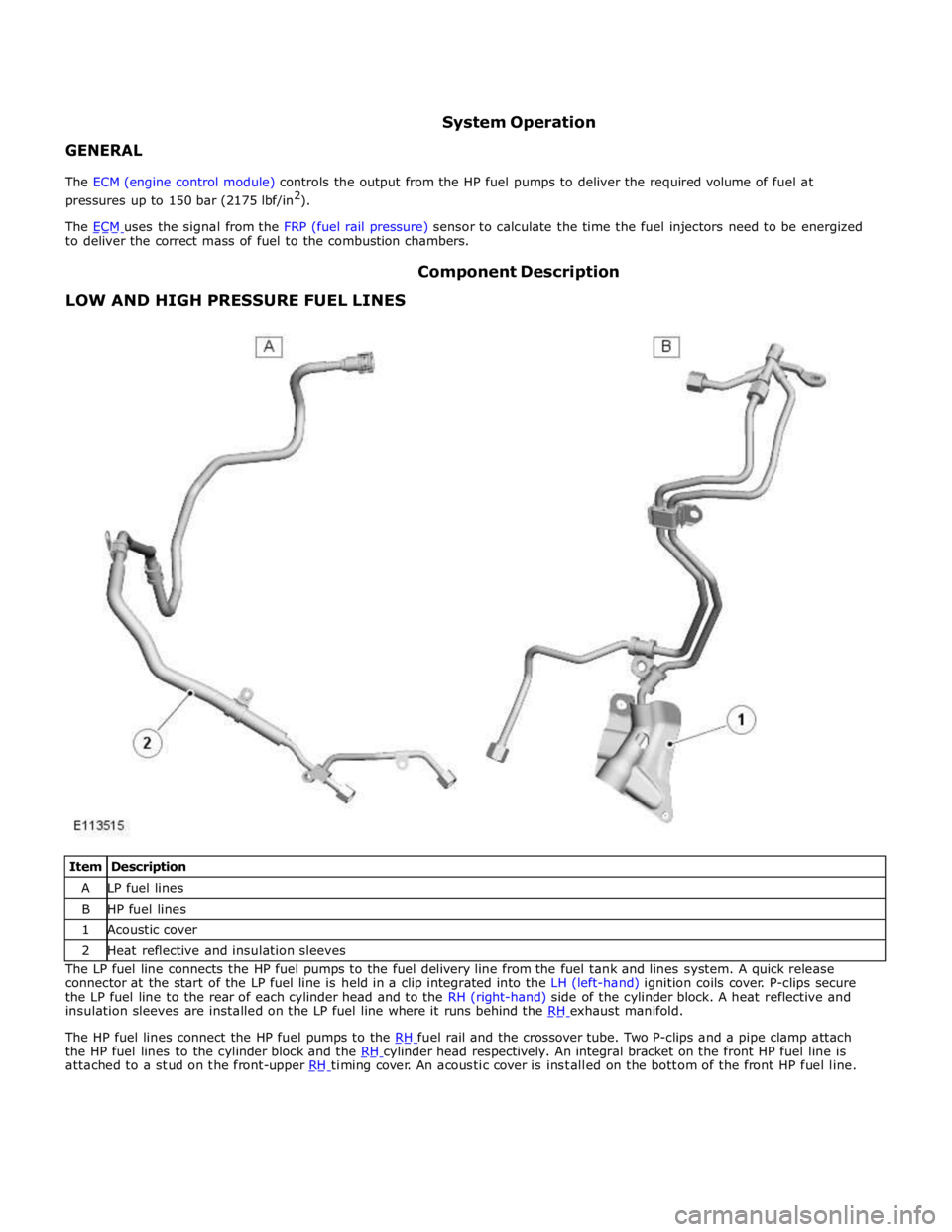
LOW AND HIGH PRESSURE FUEL LINES Component Description
Item Description A LP fuel lines B HP fuel lines 1 Acoustic cover 2 Heat reflective and insulation sleeves The LP fuel line connects the HP fuel pumps to the fuel delivery line from the fuel tank and lines system. A quick release
connector at the start of the LP fuel line is held in a clip integrated into the LH (left-hand) ignition coils cover. P-clips secure
the LP fuel line to the rear of each cylinder head and to the RH (right-hand) side of the cylinder block. A heat reflective and
insulation sleeves are installed on the LP fuel line where it runs behind the RH exhaust manifold.
The HP fuel lines connect the HP fuel pumps to the RH fuel rail and the crossover tube. Two P-clips and a pipe clamp attach the HP fuel lines to the cylinder block and the RH cylinder head respectively. An integral bracket on the front HP fuel line is attached to a stud on the front-upper RH timing cover. An acoustic cover is installed on the bottom of the front HP fuel line.
Page 1361 of 3039
DIAGNOSTICS
The ECM stores each fault as a DTC (diagnostic trouble code). The DTC and associated environmental and freeze frame data can be read using Jaguar approved diagnostic equipment, which can also read real time data from each sensor, the adaption
values currently being employed and the current fueling, ignition and idle speed settings.
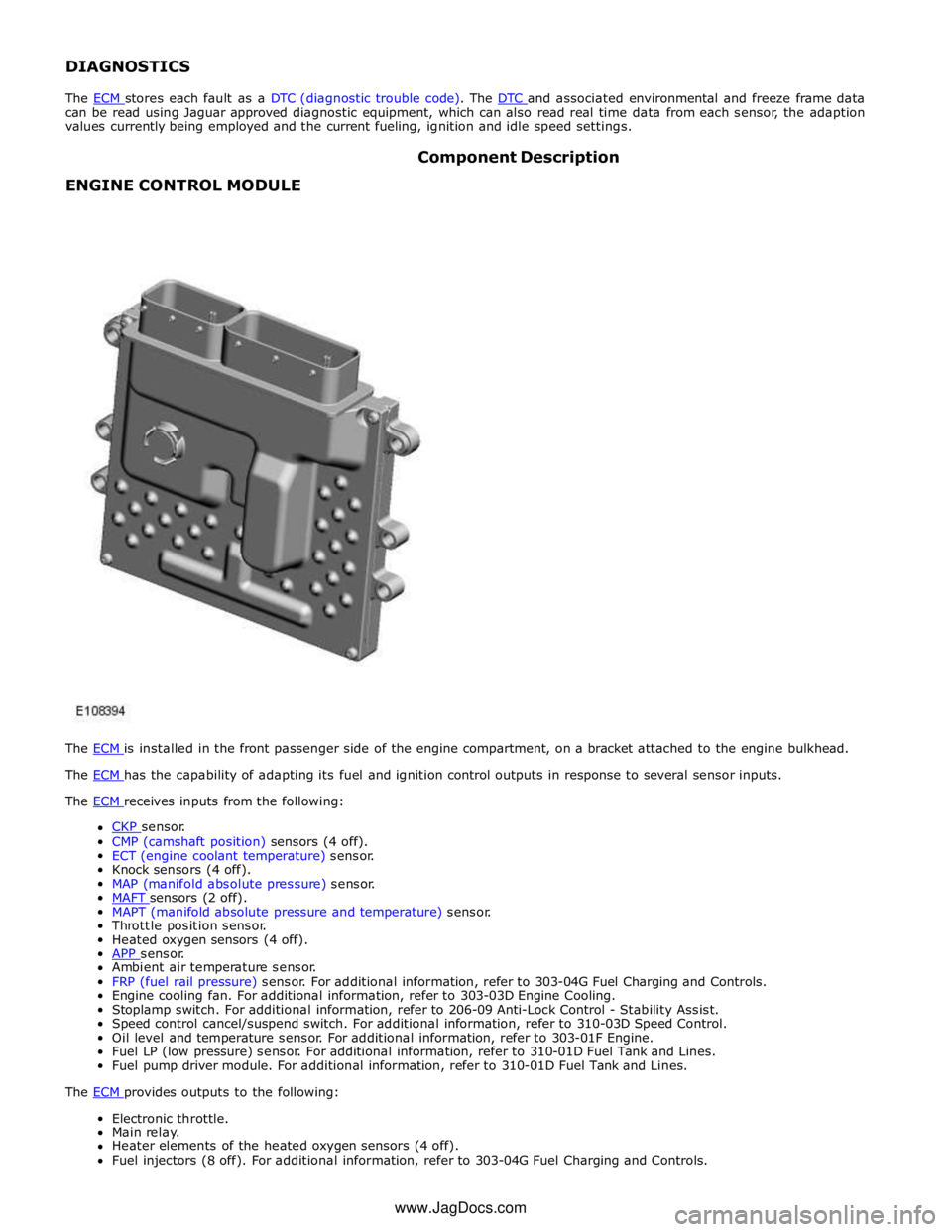
ENGINE CONTROL MODULE Component Description
The ECM is installed in the front passenger side of the engine compartment, on a bracket attached to the engine bulkhead. The ECM has the capability of adapting its fuel and ignition control outputs in response to several sensor inputs. The ECM receives inputs from the following:
CKP sensor. CMP (camshaft position) sensors (4 off).
ECT (engine coolant temperature) sensor.
Knock sensors (4 off).
MAP (manifold absolute pressure) sensor.
MAFT sensors (2 off). MAPT (manifold absolute pressure and temperature) sensor.
Throttle position sensor.
Heated oxygen sensors (4 off).
APP sensor. Ambient air temperature sensor.
FRP (fuel rail pressure) sensor. For additional information, refer to 303-04G Fuel Charging and Controls.
Engine cooling fan. For additional information, refer to 303-03D Engine Cooling.
Stoplamp switch. For additional information, refer to 206-09 Anti-Lock Control - Stability Assist.
Speed control cancel/suspend switch. For additional information, refer to 310-03D Speed Control.
Oil level and temperature sensor. For additional information, refer to 303-01F Engine.
Fuel LP (low pressure) sensor. For additional information, refer to 310-01D Fuel Tank and Lines.
Fuel pump driver module. For additional information, refer to 310-01D Fuel Tank and Lines.
The ECM provides outputs to the following: Electronic throttle.
Main relay.
Heater elements of the heated oxygen sensors (4 off).
Fuel injectors (8 off). For additional information, refer to 303-04G Fuel Charging and Controls. www.JagDocs.com
Page 1429 of 3039
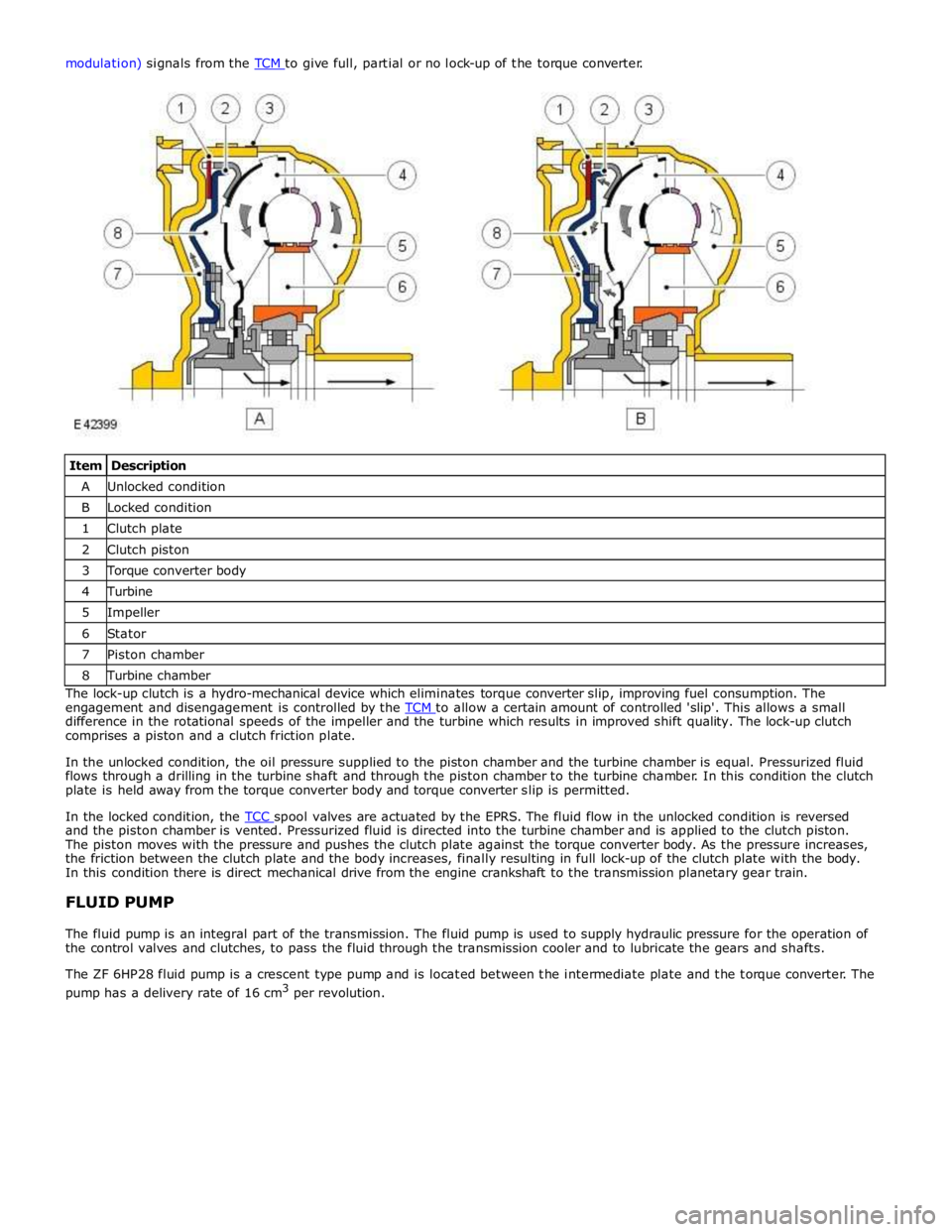
Item Description A Unlocked condition B Locked condition 1 Clutch plate 2 Clutch piston 3 Torque converter body 4 Turbine 5 Impeller 6 Stator 7 Piston chamber 8 Turbine chamber The lock-up clutch is a hydro-mechanical device which eliminates torque converter slip, improving fuel consumption. The
engagement and disengagement is controlled by the TCM to allow a certain amount of controlled 'slip'. This allows a small difference in the rotational speeds of the impeller and the turbine which results in improved shift quality. The lock-up clutch
comprises a piston and a clutch friction plate.
In the unlocked condition, the oil pressure supplied to the piston chamber and the turbine chamber is equal. Pressurized fluid
flows through a drilling in the turbine shaft and through the piston chamber to the turbine chamber. In this condition the clutch
plate is held away from the torque converter body and torque converter slip is permitted.
In the locked condition, the TCC spool valves are actuated by the EPRS. The fluid flow in the unlocked condition is reversed and the piston chamber is vented. Pressurized fluid is directed into the turbine chamber and is applied to the clutch piston.
The piston moves with the pressure and pushes the clutch plate against the torque converter body. As the pressure increases,
the friction between the clutch plate and the body increases, finally resulting in full lock-up of the clutch plate with the body.
In this condition there is direct mechanical drive from the engine crankshaft to the transmission planetary gear train.
FLUID PUMP
The fluid pump is an integral part of the transmission. The fluid pump is used to supply hydraulic pressure for the operation of
the control valves and clutches, to pass the fluid through the transmission cooler and to lubricate the gears and shafts.
The ZF 6HP28 fluid pump is a crescent type pump and is located between the intermediate plate and the torque converter. The
pump has a delivery rate of 16 cm3
per revolution.
Page 1430 of 3039
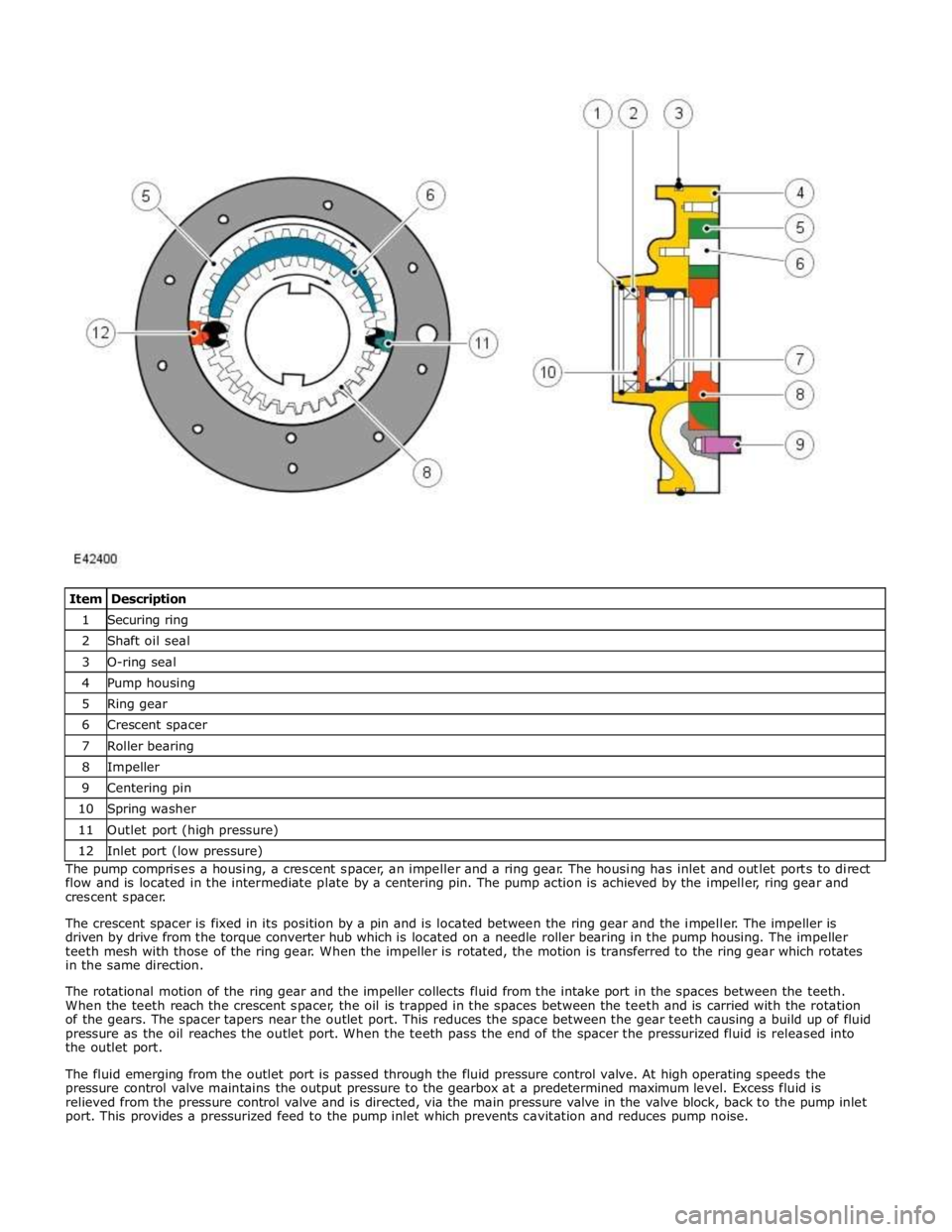
1 Securing ring 2 Shaft oil seal 3 O-ring seal 4 Pump housing 5 Ring gear 6 Crescent spacer 7 Roller bearing 8 Impeller 9 Centering pin 10 Spring washer 11 Outlet port (high pressure) 12 Inlet port (low pressure) The pump comprises a housing, a crescent spacer, an impeller and a ring gear. The housing has inlet and outlet ports to direct
flow and is located in the intermediate plate by a centering pin. The pump action is achieved by the impeller, ring gear and
crescent spacer.
The crescent spacer is fixed in its position by a pin and is located between the ring gear and the impeller. The impeller is
driven by drive from the torque converter hub which is located on a needle roller bearing in the pump housing. The impeller
teeth mesh with those of the ring gear. When the impeller is rotated, the motion is transferred to the ring gear which rotates
in the same direction.
The rotational motion of the ring gear and the impeller collects fluid from the intake port in the spaces between the teeth.
When the teeth reach the crescent spacer, the oil is trapped in the spaces between the teeth and is carried with the rotation
of the gears. The spacer tapers near the outlet port. This reduces the space between the gear teeth causing a build up of fluid
pressure as the oil reaches the outlet port. When the teeth pass the end of the spacer the pressurized fluid is released into
the outlet port.
The fluid emerging from the outlet port is passed through the fluid pressure control valve. At high operating speeds the
pressure control valve maintains the output pressure to the gearbox at a predetermined maximum level. Excess fluid is
relieved from the pressure control valve and is directed, via the main pressure valve in the valve block, back to the pump inlet
port. This provides a pressurized feed to the pump inlet which prevents cavitation and reduces pump noise.