2010 JAGUAR XFR low oil pressure
[x] Cancel search: low oil pressurePage 1825 of 3039

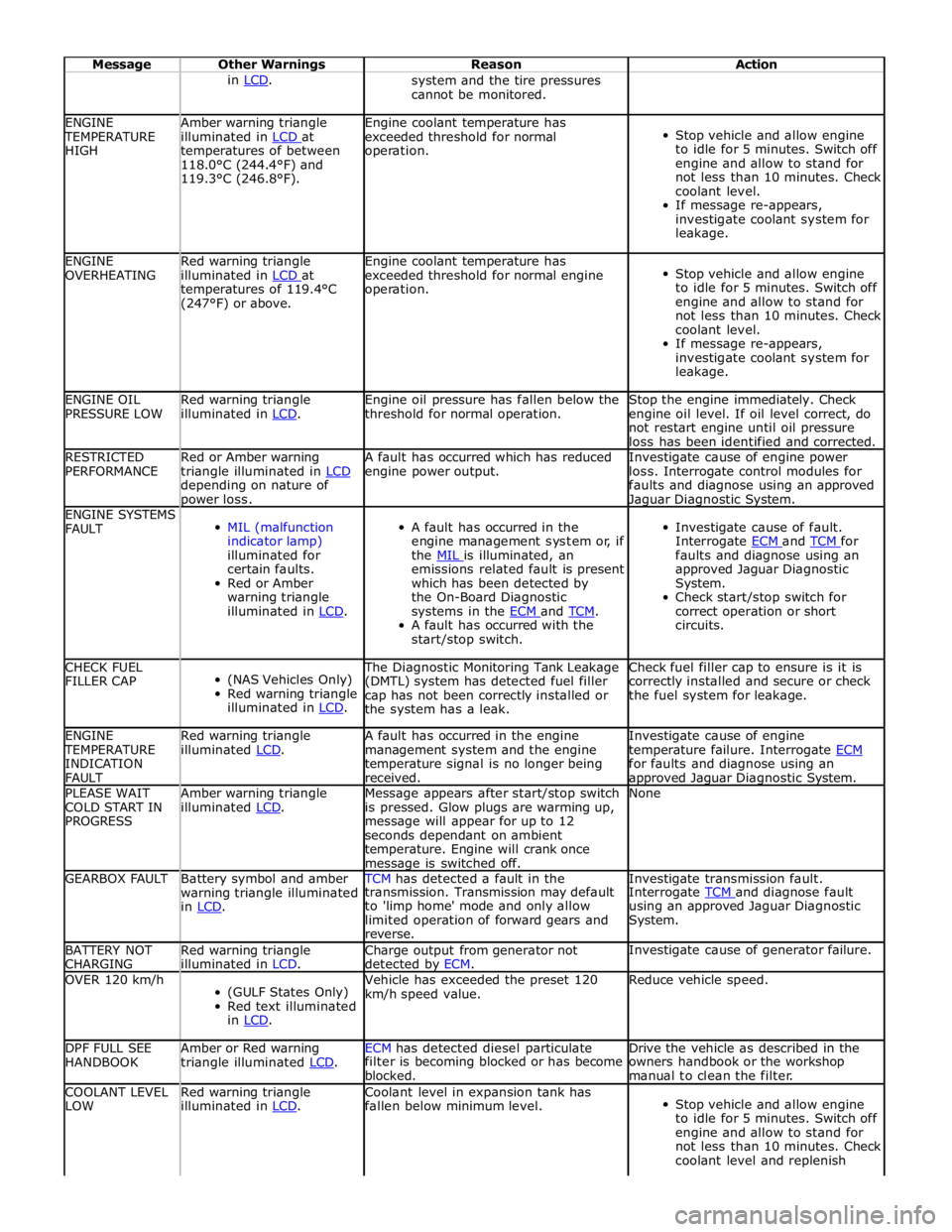
Message Other Warnings Reason Action in LCD. system and the tire pressures
cannot be monitored. ENGINE TEMPERATURE
HIGH Amber warning triangle
illuminated in LCD at temperatures of between
118.0°C (244.4°F) and
119.3°C (246.8°F). Engine coolant temperature has
exceeded threshold for normal
operation.
Stop vehicle and allow engine
to idle for 5 minutes. Switch off
engine and allow to stand for
not less than 10 minutes. Check
coolant level.
If message re-appears,
investigate coolant system for
leakage. ENGINE
OVERHEATING Red warning triangle
illuminated in LCD at temperatures of 119.4°C
(247°F) or above. Engine coolant temperature has
exceeded threshold for normal engine
operation.
Stop vehicle and allow engine
to idle for 5 minutes. Switch off
engine and allow to stand for
not less than 10 minutes. Check
coolant level.
If message re-appears,
investigate coolant system for
leakage. ENGINE OIL
PRESSURE LOW Red warning triangle
illuminated in LCD. Engine oil pressure has fallen below the
threshold for normal operation. Stop the engine immediately. Check
engine oil level. If oil level correct, do
not restart engine until oil pressure
loss has been identified and corrected. RESTRICTED
PERFORMANCE Red or Amber warning
triangle illuminated in LCD depending on nature of power loss. A fault has occurred which has reduced
engine power output. Investigate cause of engine power
loss. Interrogate control modules for
faults and diagnose using an approved Jaguar Diagnostic System. ENGINE SYSTEMS
FAULT
MIL (malfunction
indicator lamp)
illuminated for
certain faults.
Red or Amber
warning triangle
illuminated in LCD.
A fault has occurred in the
engine management system or, if
the MIL is illuminated, an emissions related fault is present
which has been detected by
the On-Board Diagnostic
systems in the ECM and TCM. A fault has occurred with the
start/stop switch.
Investigate cause of fault.
Interrogate ECM and TCM for faults and diagnose using an
approved Jaguar Diagnostic
System.
Check start/stop switch for
correct operation or short
circuits. CHECK FUEL
FILLER CAP
(NAS Vehicles Only)
Red warning triangle
illuminated in LCD. The Diagnostic Monitoring Tank Leakage
(DMTL) system has detected fuel filler
cap has not been correctly installed or
the system has a leak. Check fuel filler cap to ensure is it is
correctly installed and secure or check
the fuel system for leakage. ENGINE TEMPERATURE
INDICATION
FAULT Red warning triangle
illuminated LCD. A fault has occurred in the engine
management system and the engine
temperature signal is no longer being
received. Investigate cause of engine
temperature failure. Interrogate ECM for faults and diagnose using an approved Jaguar Diagnostic System. PLEASE WAIT
COLD START IN
PROGRESS Amber warning triangle
illuminated LCD. Message appears after start/stop switch
is pressed. Glow plugs are warming up,
message will appear for up to 12
seconds dependant on ambient
temperature. Engine will crank once message is switched off. None GEARBOX FAULT
Battery symbol and amber
warning triangle illuminated
in LCD. TCM has detected a fault in the Investigate transmission fault. transmission. Transmission may default
to 'limp home' mode and only allow
limited operation of forward gears and
reverse. Interrogate TCM and diagnose fault using an approved Jaguar Diagnostic
System. BATTERY NOT
CHARGING Red warning triangle
illuminated in LCD. Charge output from generator not
detected by ECM. Investigate cause of generator failure. OVER 120 km/h
(GULF States Only)
Red text illuminated
in LCD. Vehicle has exceeded the preset 120
km/h speed value. Reduce vehicle speed. DPF FULL SEE
HANDBOOK Amber or Red warning
triangle illuminated LCD. ECM has detected diesel particulate Drive the vehicle as described in the filter is becoming blocked or has become
blocked. owners handbook or the workshop
manual to clean the filter. COOLANT LEVEL
LOW Red warning triangle
illuminated in LCD. Coolant level in expansion tank has
fallen below minimum level.
Stop vehicle and allow engine
to idle for 5 minutes. Switch off
engine and allow to stand for
not less than 10 minutes. Check
coolant level and replenish
Page 2146 of 3039

Check the Starter Relay circuit.
NOTE: On petrol engine variants, due to Smart Start, both sides of Relay Coil are switched directly from ECM (If
conditions correct). On diesel engine variants the low side only is switched directly from the ECM.
Check that the Steering Column Lock correctly operates and the steering wheel can turn freely.
Check that the High Speed CAN network is not malfunctioning, i.e. the CAN circuit is open or short circuit. This would mean
that the instrument cluster and ECM would be unable to communicate resulting in no Challenge being performed to enable the
ECM. This would be supported by LED Flash Code 24, see PATS Fault Code Table.
Also check the CAN network between the ABS module and the CJB. The CJB uses the CAN_BrakePressureTMC signal to
determine if the brake pedal has been pressed in order to allow an engine crank. The CJB uses a value of 0x05, if the CJB sees
a value less than this, it will not enable the Crank Request Output.
Engine cranks but will not start
If the Engine is cranking it means that the ECM has passed the authorisation required with the Instrument Cluster. If this
authorisation failed, the ECM would not engage the starter relay. This could be confirmed by verifying the PATS LED prove out
(illuminated solid for 3 seconds) or by reading DTCs from the instrument cluster and ECM.
In this case, the fuel pump circuit should be verified. The Fuel Pump Delivery Module (FPDM), which is supplied via the RJB
(authentication required with the instrument cluster) and controlled by the ECM, supplies the fuel pump.
In all cases of suspected non-start issues, the most logical failure modes should be eliminated first. i.e.
1. Check all relevant supplies and grounds to the relevant modules listed herein.
2. Note any unusual behaviour from other systems/functionality.
3. Note any functions that are not operating as expected.
PATS Fault Codes
For the various PATS modes/faults listed in the table , the instrument cluster will store a DTC and indicate this to the customer
during the detection period defined in the 'when logged' column, by illuminating the indicator as described for 60 seconds and
then flashing the LED 10 times as appropriate. The indication will stop immediately the ignition status is set to OFF any time
during the fault indication sequence. Up to 4 DTCs could be stored per key read sequence (1-10 read attempts). No DTCs will be
stored until all retry attempts are complete. Only the highest priority fault code will be flashed.
To determine the fault code from the LED: The LED will flash initially ten times with 1.5 seconds between. The LED will remain
OFF for 2.5 seconds then flash a number of times with 0.5 seconds between (the number of times the LED flashes represents
the first digit of the code), the LED will remain OFF for 1.5 seconds then flash a number of times with 1.5 seconds between
(the number of times the LED flashes represents the second digit of the code).
The PATS LED will be commanded on as shown under 'indication'. Normal PATS operations are complete within 400ms of the
ignition switch transition from OFF to ON or START, worst case for ECM communication problems will be less than 2 seconds. If
PATS is not complete during the 2 seconds the ECM will terminate PATS and await the next ignition ON or START event. PATS
faults will be indicated via the LED as soon as possible and will terminate the LED prove out. At ignition OFF all previous
flashing will cease and the perimeter anti-theft system will control the LED when the vehicle is locked and armed.
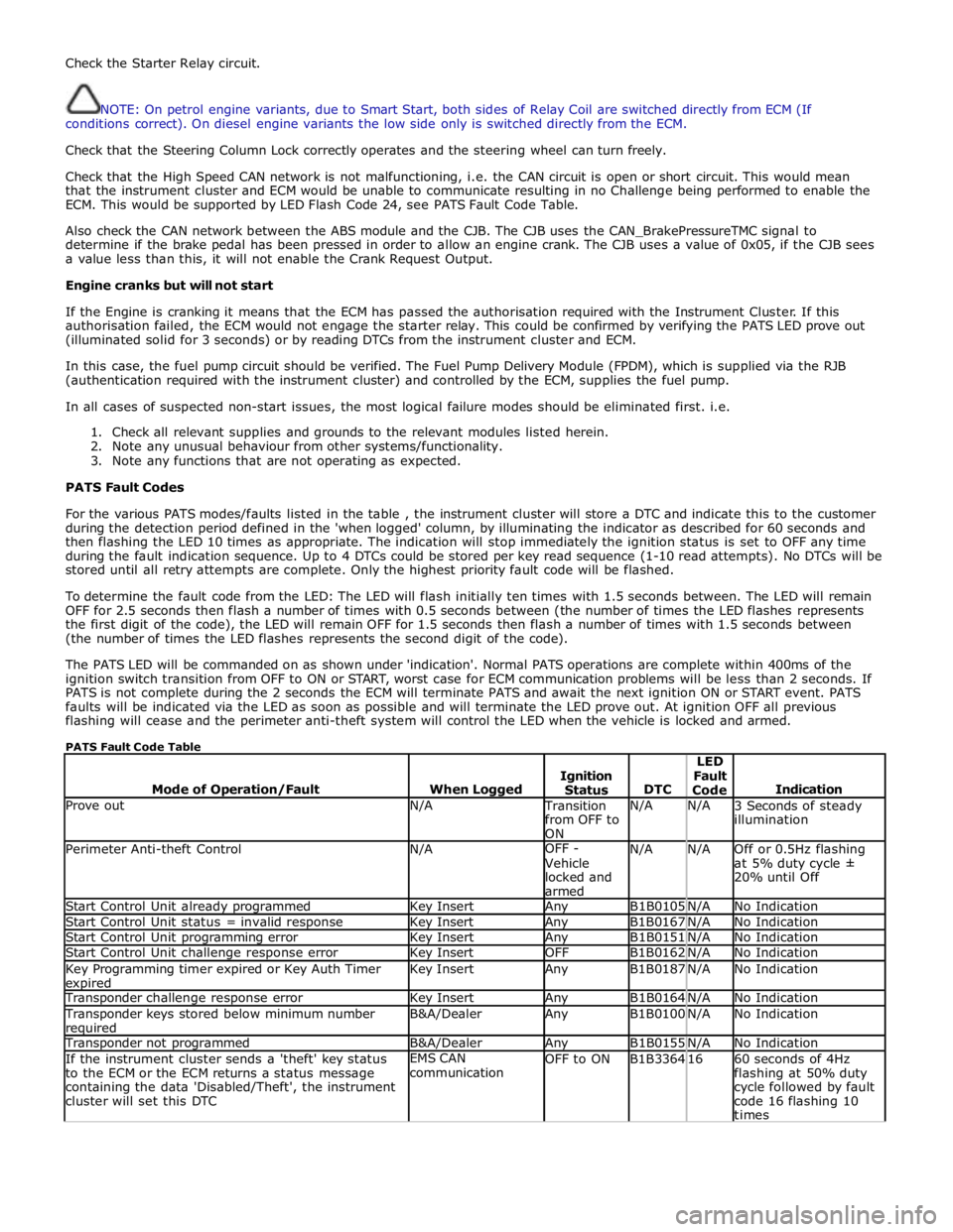
PATS Fault Code Table
Mode of Operation/Fault
When Logged
Ignition
Status
DTC LED
Fault
Code
Indication Prove out N/A Transition
from OFF to
ON N/A N/A
3 Seconds of steady
illumination Perimeter Anti-theft Control N/A OFF -
Vehicle
locked and
armed N/A N/A
Off or 0.5Hz flashing
at 5% duty cycle ±
20% until Off Start Control Unit already programmed Key Insert Any B1B0105 N/A No Indication Start Control Unit status = invalid response Key Insert Any B1B0167 N/A No Indication Start Control Unit programming error Key Insert Any B1B0151 N/A No Indication Start Control Unit challenge response error Key Insert OFF B1B0162 N/A No Indication Key Programming timer expired or Key Auth Timer expired Key Insert Any B1B0187 N/A No Indication Transponder challenge response error Key Insert Any B1B0164 N/A No Indication Transponder keys stored below minimum number required B&A/Dealer Any B1B0100 N/A No Indication Transponder not programmed B&A/Dealer Any B1B0155 N/A No Indication If the instrument cluster sends a 'theft' key status
to the ECM or the ECM returns a status message
containing the data 'Disabled/Theft', the instrument
cluster will set this DTC EMS CAN
communication OFF to ON B1B3364 16
60 seconds of 4Hz
flashing at 50% duty
cycle followed by fault
code 16 flashing 10
times