Page 1585 of 3039
Published: 11-May-2011
Fuel Tank and Lines - V8 5.0L Petrol/V8 S/C 5.0L Petrol - Fuel Tank and Lines - System Operation and Component Description
Description and Operation
Control Diagram
NOTE: A = Hardwired
Item Description 1 Battery 2 Megafuse (250A) 3 RJB (rear junction box) 4 CJB (central junction box). 5 ECM (engine control module) 6 DMTL Pump
Page 1791 of 3039

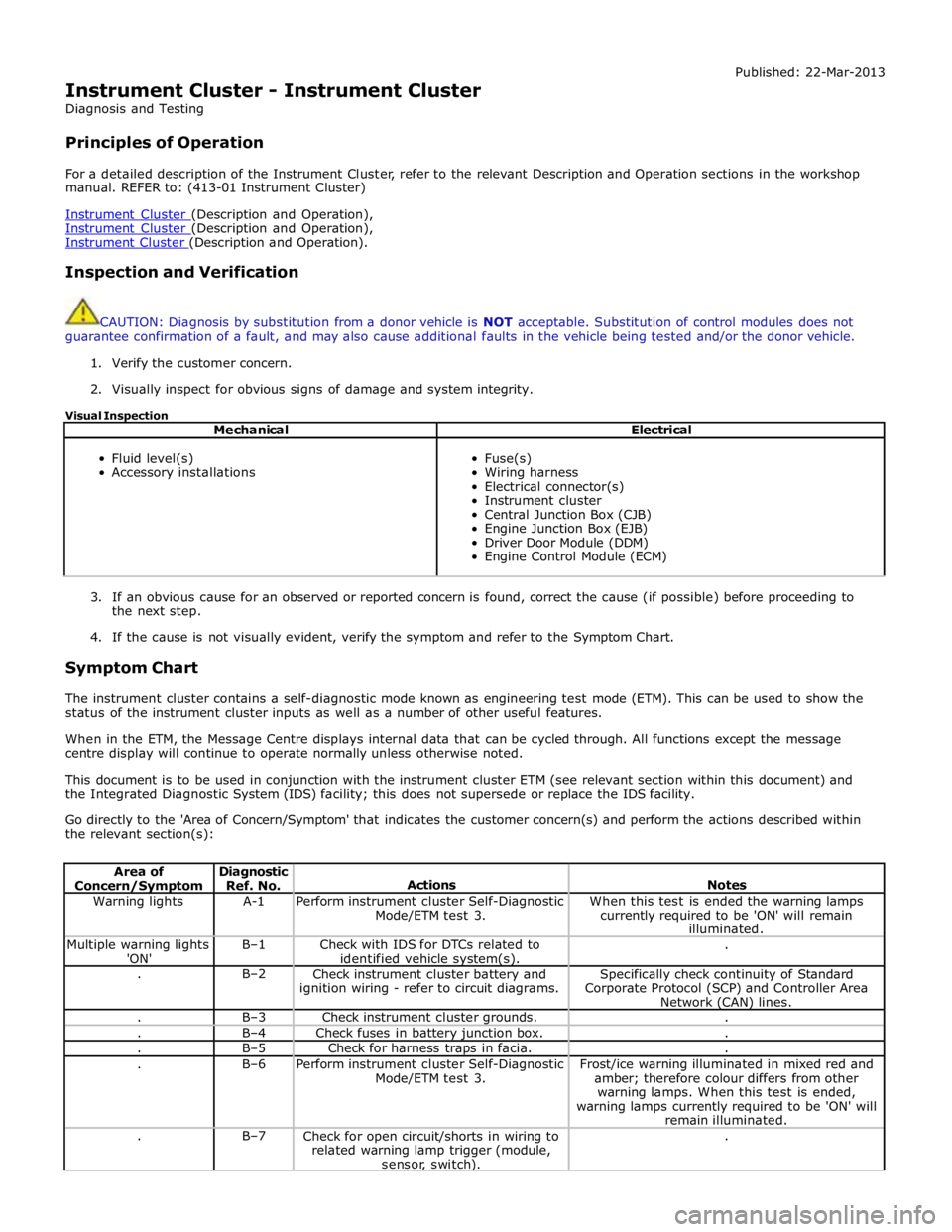
Instrument Cluster - Instrument Cluster
Diagnosis and Testing
Principles of Operation Published: 22-Mar-2013
For a detailed description of the Instrument Cluster, refer to the relevant Description and Operation sections in the workshop
manual. REFER to: (413-01 Instrument Cluster)
Instrument Cluster (Description and Operation), Instrument Cluster (Description and Operation), Instrument Cluster (Description and Operation).
Inspection and Verification
CAUTION: Diagnosis by substitution from a donor vehicle is NOT acceptable. Substitution of control modules does not
guarantee confirmation of a fault, and may also cause additional faults in the vehicle being tested and/or the donor vehicle.
1. Verify the customer concern.
2. Visually inspect for obvious signs of damage and system integrity.
Visual Inspection
Mechanical Electrical
Fluid level(s)
Accessory installations
Fuse(s)
Wiring harness
Electrical connector(s)
Instrument cluster
Central Junction Box (CJB)
Engine Junction Box (EJB)
Driver Door Module (DDM)
Engine Control Module (ECM)
3. If an obvious cause for an observed or reported concern is found, correct the cause (if possible) before proceeding to
the next step.
4. If the cause is not visually evident, verify the symptom and refer to the Symptom Chart.
Symptom Chart
The instrument cluster contains a self-diagnostic mode known as engineering test mode (ETM). This can be used to show the
status of the instrument cluster inputs as well as a number of other useful features.
When in the ETM, the Message Centre displays internal data that can be cycled through. All functions except the message
centre display will continue to operate normally unless otherwise noted.
This document is to be used in conjunction with the instrument cluster ETM (see relevant section within this document) and
the Integrated Diagnostic System (IDS) facility; this does not supersede or replace the IDS facility.
Go directly to the 'Area of Concern/Symptom' that indicates the customer concern(s) and perform the actions described within
the relevant section(s):
Area of Concern/Symptom Diagnostic
Ref. No.
Actions
Notes Warning lights A-1
Perform instrument cluster Self-Diagnostic
Mode/ETM test 3. When this test is ended the warning lamps
currently required to be 'ON' will remain
illuminated. Multiple warning lights
'ON' B–1
Check with IDS for DTCs related to
identified vehicle system(s). . . B–2
Check instrument cluster battery and
ignition wiring - refer to circuit diagrams. Specifically check continuity of Standard
Corporate Protocol (SCP) and Controller Area
Network (CAN) lines. . B–3 Check instrument cluster grounds. . . B–4 Check fuses in battery junction box. . . B–5 Check for harness traps in facia. . . B–6
Perform instrument cluster Self-Diagnostic
Mode/ETM test 3. Frost/ice warning illuminated in mixed red and
amber; therefore colour differs from other
warning lamps. When this test is ended,
warning lamps currently required to be 'ON' will
remain illuminated. . B–7
Check for open circuit/shorts in wiring to
related warning lamp trigger (module,
sensor, switch). .
Page 2025 of 3039
7 LH headlamp assembly 8 Lighting control switch - LH steering column multifunction switch 9 Instrument cluster SIDE LAMPS/TURN SIGNAL INDICATORS/FOG LAMPS - CONTROL DIAGRAM
Item Description A = Hardwired; N = Medium speed CAN bus; O = LIN bus 1 Battery 2 BJB - Megafuse 3 Stop lamp switch 4 LH turn signal indicator 5 RJB (rear junction box) 6 RH turn signal indicator 7 RH licence plate lamp www.JagDocs.com
Page 2057 of 3039
8 Passenger door module 9 LH (left-hand) rear door latch 10 RH (right-hand) rear door latch 11 LH front door latch 12 RH front door latch 13 CJB (central junction box) 14 LH front door handle LED (light emitting diode) illumination 15 RH front door handle LED illumination CONTROL DIAGRAM (SHEET 2 OF 2)
Item Description A = Hardwired 1 Battery 2 BJB - Megafuse
Page 2122 of 3039
Published: 11-May-2011
Anti-Theft - Active - Anti-Theft - Active - System Operation and Component Description
Description and Operation
Control Diagram
NOTE: A = Hardwired; N = Medium speed CAN; O = LIN bus
Item Description 1 Battery 2 Megafuse (250 amp) 3 RJB (rear junction box) 4 CJB (central junction box) 5 Vehicle horn 6 Keyless vehicle module
Page 2414 of 3039
Published: 24-Jan-2013
Glass, Frames and Mechanisms - Glass, Frames and Mechanisms - System
Operation and Component Description
Description and Operation
Control Diagram
NOTE: A = Hardwired; N = Medium speed CAN; O = LIN bus
Item Description 1 Battery 2 Megafuse (250 amp) 3 CJB (central junction box) 4 RJB (rear junction box) 5 Window control switches - driver's door 6 Door module – driver's door www.JagDocs.com
Page 2561 of 3039
Published: 11-May-2011
Roof Opening Panel - Roof Opening Panel - System Operation and
Component Description
Description and Operation
Control Diagram
NOTE: A = Hardwired
Item Description 1 Battery 2 Megafuse (250 A) 3 Rear window sunblind, switch 4 Rear window sunblind, motor 5 ABS (anti-lock brake system) module 6 Roof opening panel, control module 7 Roof opening panel, rocker switch 8 CJB (central junction box)
Page:
< prev 1-8 9-16 17-24