2010 JAGUAR XFR fuel type
[x] Cancel search: fuel typePage 1589 of 3039
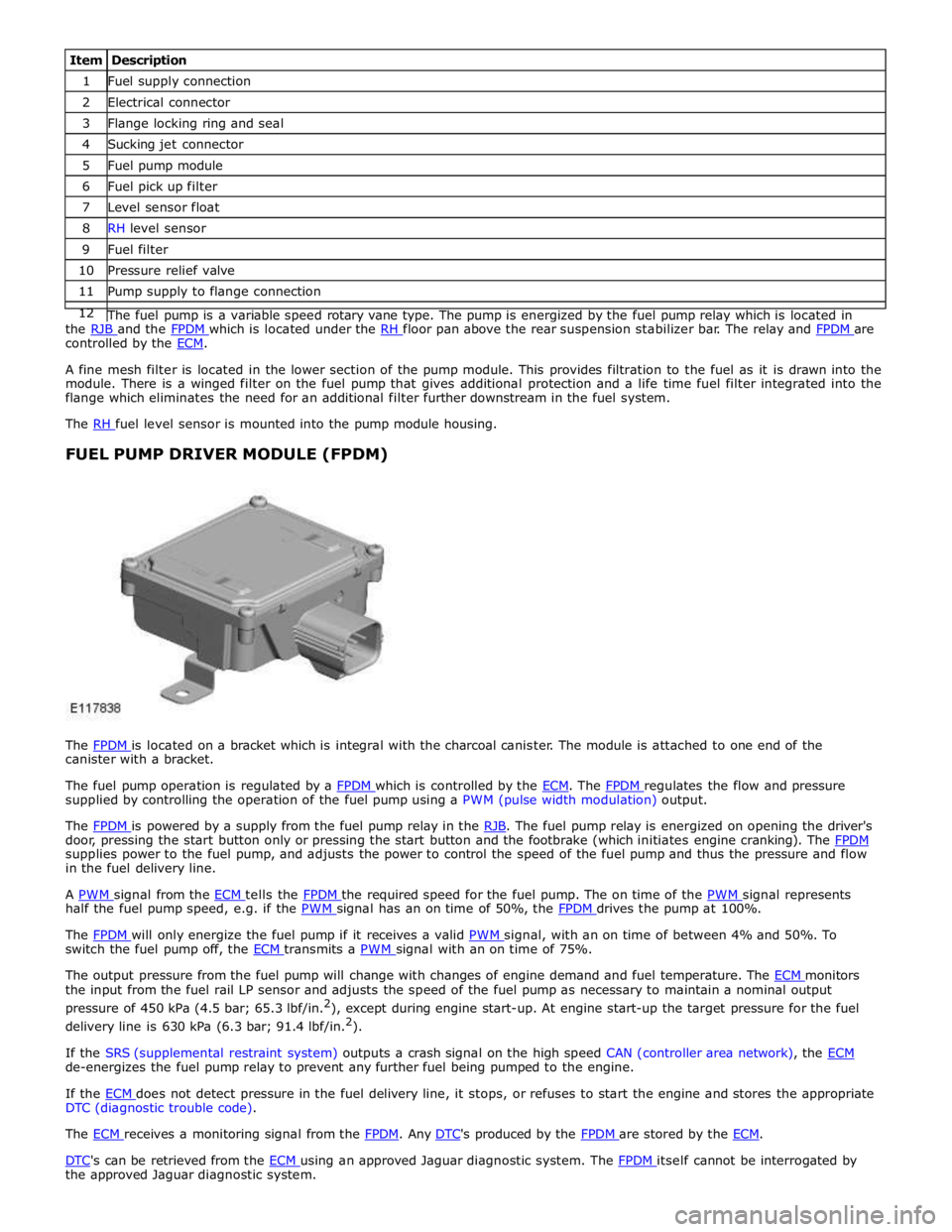
1 Fuel supply connection 2 Electrical connector 3 Flange locking ring and seal 4 Sucking jet connector 5 Fuel pump module 6 Fuel pick up filter 7 Level sensor float 8 RH level sensor 9 Fuel filter 10 Pressure relief valve 11 Pump supply to flange connection 12 The fuel pump is a variable speed rotary vane type. The pump is energized by the fuel pump relay which is located in the RJB and the FPDM which is located under the RH floor pan above the rear suspension stabilizer bar. The relay and FPDM are controlled by the ECM.
A fine mesh filter is located in the lower section of the pump module. This provides filtration to the fuel as it is drawn into the
module. There is a winged filter on the fuel pump that gives additional protection and a life time fuel filter integrated into the
flange which eliminates the need for an additional filter further downstream in the fuel system.
The RH fuel level sensor is mounted into the pump module housing.
FUEL PUMP DRIVER MODULE (FPDM)
The FPDM is located on a bracket which is integral with the charcoal canister. The module is attached to one end of the canister with a bracket.
The fuel pump operation is regulated by a FPDM which is controlled by the ECM. The FPDM regulates the flow and pressure supplied by controlling the operation of the fuel pump using a PWM (pulse width modulation) output.
The FPDM is powered by a supply from the fuel pump relay in the RJB. The fuel pump relay is energized on opening the driver's door, pressing the start button only or pressing the start button and the footbrake (which initiates engine cranking). The FPDM supplies power to the fuel pump, and adjusts the power to control the speed of the fuel pump and thus the pressure and flow
in the fuel delivery line.
A PWM signal from the ECM tells the FPDM the required speed for the fuel pump. The on time of the PWM signal represents half the fuel pump speed, e.g. if the PWM signal has an on time of 50%, the FPDM drives the pump at 100%.
The FPDM will only energize the fuel pump if it receives a valid PWM signal, with an on time of between 4% and 50%. To switch the fuel pump off, the ECM transmits a PWM signal with an on time of 75%.
The output pressure from the fuel pump will change with changes of engine demand and fuel temperature. The ECM monitors the input from the fuel rail LP sensor and adjusts the speed of the fuel pump as necessary to maintain a nominal output
pressure of 450 kPa (4.5 bar; 65.3 lbf/in.2
), except during engine start-up. At engine start-up the target pressure for the fuel
delivery line is 630 kPa (6.3 bar; 91.4 lbf/in.2
).
If the SRS (supplemental restraint system) outputs a crash signal on the high speed CAN (controller area network), the ECM de-energizes the fuel pump relay to prevent any further fuel being pumped to the engine.
If the ECM does not detect pressure in the fuel delivery line, it stops, or refuses to start the engine and stores the appropriate DTC (diagnostic trouble code).
The ECM receives a monitoring signal from the FPDM. Any DTC's produced by the FPDM are stored by the ECM.
DTC's can be retrieved from the ECM using an approved Jaguar diagnostic system. The FPDM itself cannot be interrogated by the approved Jaguar diagnostic system.
Page 1593 of 3039
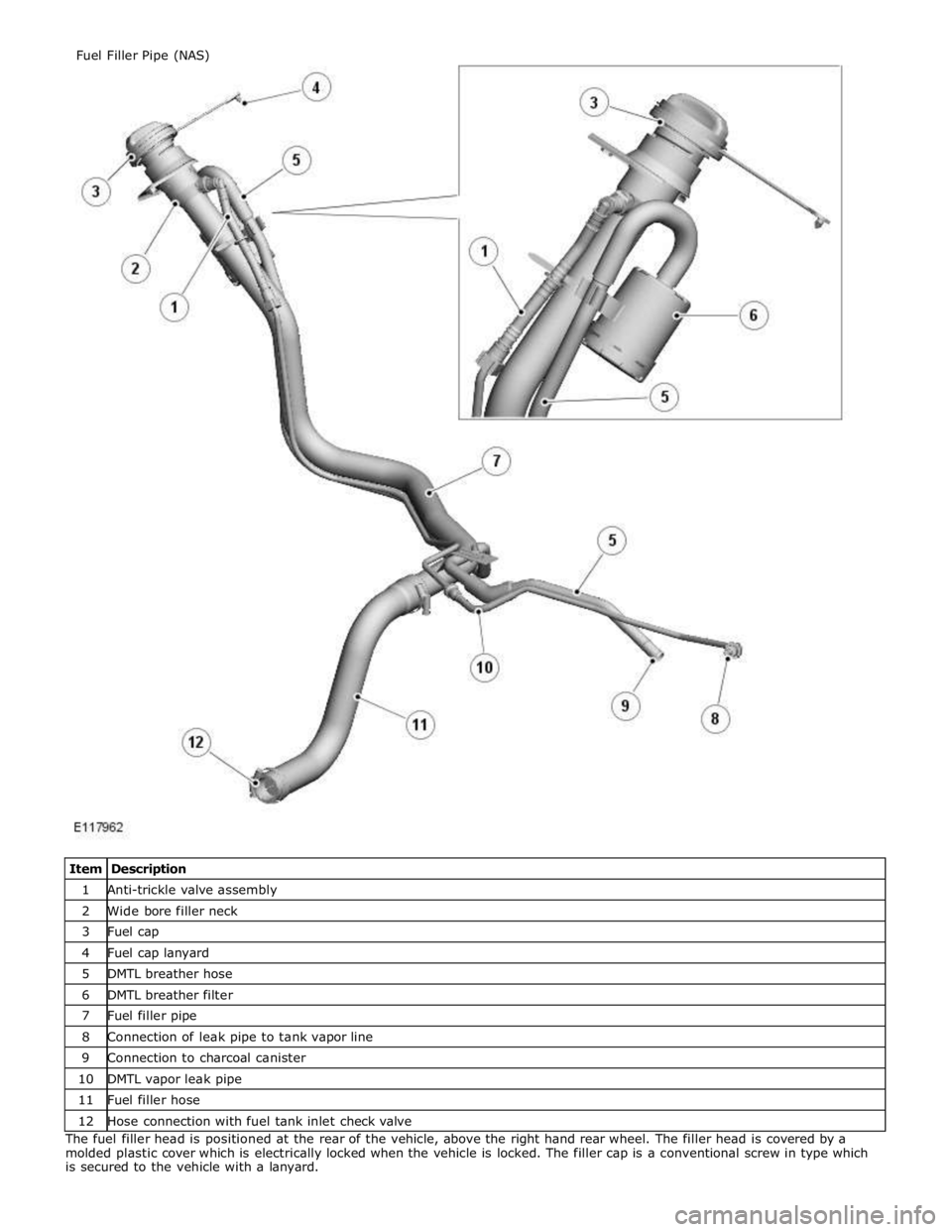
1 Anti-trickle valve assembly 2 Wide bore filler neck 3 Fuel cap 4 Fuel cap lanyard 5 DMTL breather hose 6 DMTL breather filter 7 Fuel filler pipe 8 Connection of leak pipe to tank vapor line 9 Connection to charcoal canister 10 DMTL vapor leak pipe 11 Fuel filler hose 12 Hose connection with fuel tank inlet check valve The fuel filler head is positioned at the rear of the vehicle, above the right hand rear wheel. The filler head is covered by a
molded plastic cover which is electrically locked when the vehicle is locked. The filler cap is a conventional screw in type which
is secured to the vehicle with a lanyard. Fuel Filler Pipe (NAS)
Page 1614 of 3039
Published: 31-Oct-2013
Fuel Tank and Lines - V8 5.0L Petrol/V8 S/C 5.0L Petrol - Fuel Rail High-Pressure Fuel Pump Supply Line
Removal and Installation
Removal
NOTES:
Some variation in the illustrations may occur, but the essential information is always correct.
Some illustrations may show the engine removed for clarity.
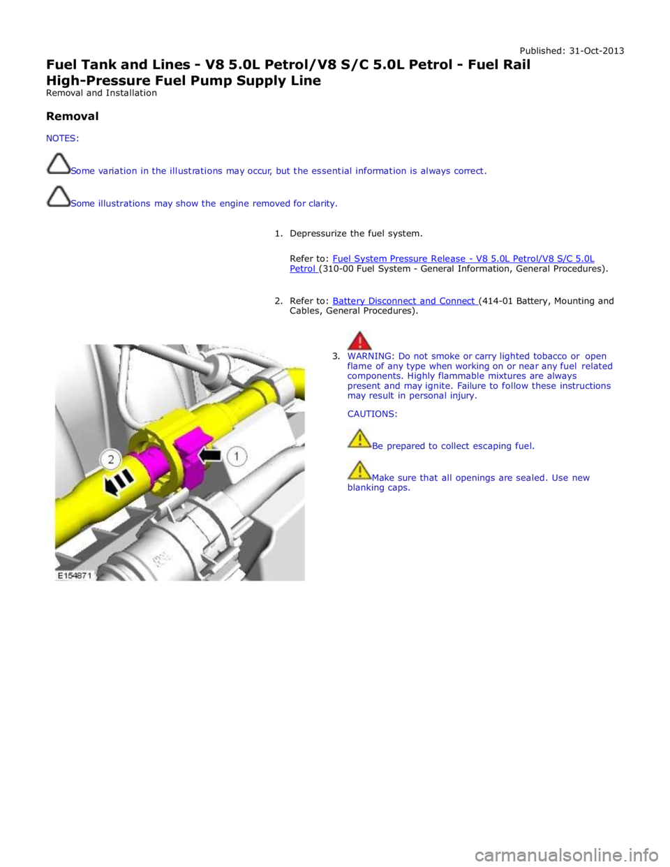
1. Depressurize the fuel system.
Refer to: Fuel System Pressure Release - V8 5.0L Petrol/V8 S/C 5.0L Petrol (310-00 Fuel System - General Information, General Procedures).
2. Refer to: Battery Disconnect and Connect (414-01 Battery, Mounting and Cables, General Procedures).
3. WARNING: Do not smoke or carry lighted tobacco or open
flame of any type when working on or near any fuel related
components. Highly flammable mixtures are always
present and may ignite. Failure to follow these instructions
may result in personal injury.
CAUTIONS:
Be prepared to collect escaping fuel.
Make sure that all openings are sealed. Use new
blanking caps.
Page 1618 of 3039
15.
13.
14.
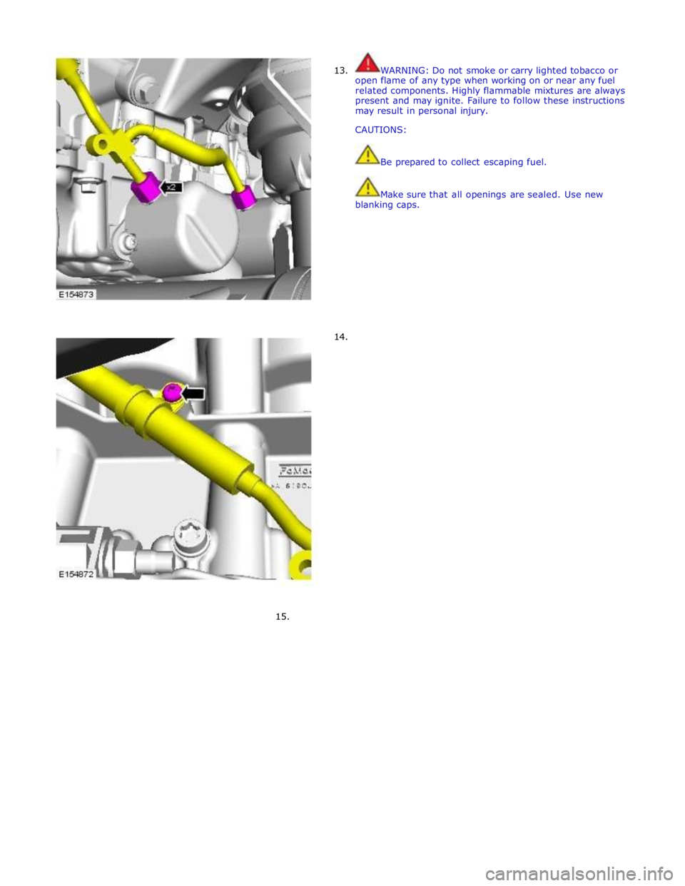
WARNING: Do not smoke or carry lighted tobacco or
open flame of any type when working on or near any fuel
related components. Highly flammable mixtures are always
present and may ignite. Failure to follow these instructions
may result in personal injury.
CAUTIONS:
Be prepared to collect escaping fuel.
Make sure that all openings are sealed. Use new
blanking caps.
Page 2695 of 3039
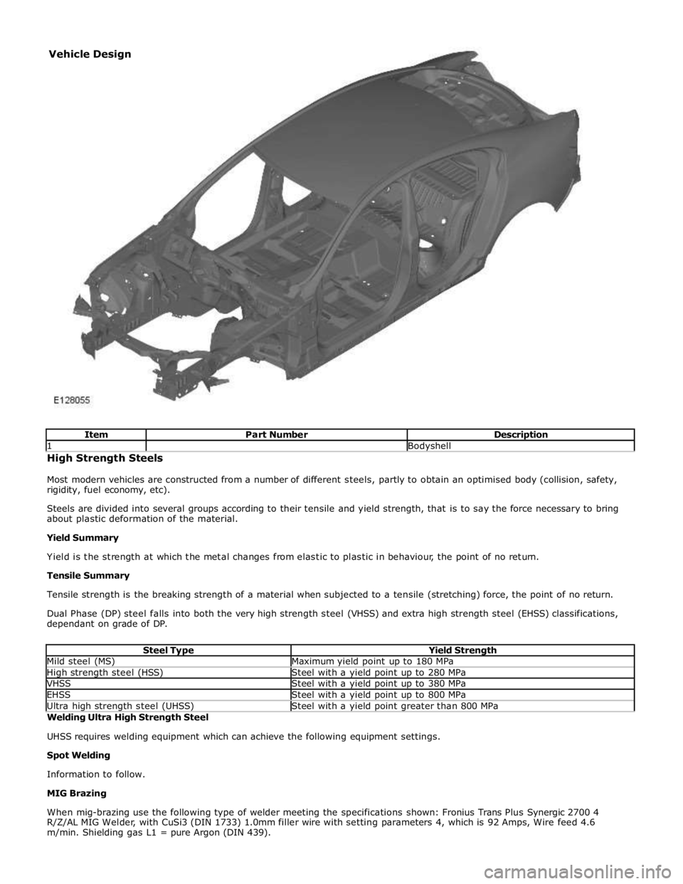
1 Bodyshell High Strength Steels
Most modern vehicles are constructed from a number of different steels, partly to obtain an optimised body (collision, safety,
rigidity, fuel economy, etc).
Steels are divided into several groups according to their tensile and yield strength, that is to say the force necessary to bring
about plastic deformation of the material.
Yield Summary
Yield is the strength at which the metal changes from elastic to plastic in behaviour, the point of no return.
Tensile Summary
Tensile strength is the breaking strength of a material when subjected to a tensile (stretching) force, the point of no return.
Dual Phase (DP) steel falls into both the very high strength steel (VHSS) and extra high strength steel (EHSS) classifications,
dependant on grade of DP.
Steel Type Yield Strength Mild steel (MS) Maximum yield point up to 180 MPa High strength steel (HSS) Steel with a yield point up to 280 MPa VHSS Steel with a yield point up to 380 MPa EHSS Steel with a yield point up to 800 MPa Ultra high strength steel (UHSS) Steel with a yield point greater than 800 MPa Welding Ultra High Strength Steel
UHSS requires welding equipment which can achieve the following equipment settings.
Spot Welding
Information to follow.
MIG Brazing
When mig-brazing use the following type of welder meeting the specifications shown: Fronius Trans Plus Synergic 2700 4
R/Z/AL MIG Welder, with CuSi3 (DIN 1733) 1.0mm filler wire with setting parameters 4, which is 92 Amps, Wire feed 4.6
m/min. Shielding gas L1 = pure Argon (DIN 439). Vehicle Design
Page 2714 of 3039
- Disadvantage: Scarring and hardening of the surface.
Flattening using a copper electrode.
- Small, sharp dents that face outwards can be worked on with a copper electrode.
Flattening using a flame and body files.
NOTE: When applied correctly, this method can be used with all the attached parts still in place (roof headlining,
wiring harnesses etc.).
- Small, soft dents (only slight stretching): Working at the edges of the dent in an inward spiral pattern, the dent
is heated with an oxyacetylene torch (torch size 1 - 2 mm, excess gas flame) to approx. 250° C.
- Working rapidly with a body file extracts heat from the edge area until the dent is flattened. Preferably alternate
between two files. This increases the amount of heat that can be extracted.
Safety measures
The electronic control modules (ECM) fitted to vehicles make it advisable to follow suitable precautions prior to carrying
out welding repair operations. Harsh conditions of heat and vibration may be generated during these operations which
could cause damage to the modules. In particular, it is essential to follow the appropriate precautions when
disconnecting or removing the airbag RCM.
Do not allow electronic modules or lines to come into contact with the ground connection or the welding electrode.
Seat belt anchorages are a safety critical. When making repairs in these areas, it is essential to follow design
specifications. Note that extra strength low alloy steel may be used for seat belt anchorages. Where possible, the
original production assembly should be used, complete with its seat belt anchorages, or the cut line should be so
arranged that the original seat belt anchorage is not disturbed.
All welds within 250mm (9.842) of seat belt anchorages must be carefully checked for weld quality, including spacing of
spot welds.
Remove the battery before carrying out welding work in its vicinity.
Utmost care must be taken when welding near the fuel tank or other components that contain fuel. If the tank filler
neck or a fuel line must be detached to allow access for welding work, then the fuel tank must be drained and removed.
Never weld, on components of a filled air conditioning system. The same applies if there is a risk of the air conditioning
system heating up.
Connect the ground connection of the electrical welder directly to the part that is to be welded. Make sure that there
are no electrically insulating parts between the ground connection and the welding point.
Adjacent vehicle parts and adjacent vehicles must be shielded against flying sparks and heat.
Pedestrian protection system
The pedestrian protection system is designed to mitigate injuries in a pedestrian collision with the vehicle. It does this by
utilizing a pair of pyrotechnic actuators to lift the hood away from the engine, creating a cushioned impact between the
pedestrian and the vehicle. It is essential that any repair or replacement operations do not affect the safe working of the
system.
For additional information, refer to: Pedestrian Protection System (501-20C Pedestrian Protection System, Description and Operation).
Resistance spot welding
Where resistance spot welds have been used in production, they must be reproduced with new spot welds in replacement
where possible. All such reproduction spot welds should be spaced 25 to 30mm apart.
Setting up the equipment and co-ordinating the welding parameters.
Equipment:
- Follow the equipment manufacturer's instructions for the equipment settings.
- Select the correct electrode arms (as short as possible).
- Align the electrode arms and tips exactly.
- Electrode tips should be convex (rough shaping with a file, fine shaping with a sanding block).
Body:
- Make sure that the flanges to be joined lie perfectly flat to one another.
- Prepare a bare metal joint surface (inside and outside).
Notes on technique/method:
- Carry out a test weld on a sample piece of the material coated in welding paste.
- If any metal parts are located between the electrode arms then there will be a loss of induction and therefore
power (adjust current setting).
- The power needs to be adjusted for high-strength low alloy steel.
- Repeated welding on old welding points often leads to poor quality welds.
- Keep the electrode tips as near as possible to an angle of 90° to the contact surface.
- Keep the pressure on the electrodes for a short period after finishing the weld.
- The electrodes work best if their shape is convex. Clean the contact surface of the electrodes regularly.
Resistance spot welding panels where the total thickness is 3 mm or more
For all repairs to modern Jaguar vehicles, spot-welding equipment should be suitable for reliable welding of zinc-plated,
high-strength and high-tensile steels in three or more layers, up to 5 mm total thickness. If these requirements are not
fulfilled, plug welding must be used for safety reasons. The electrical specifications (current, resistance, heat) of the
spot-welding equipment have different validity, depending upon the type of equipment. Therefore, it is essential that the
manufacturer's instructions are observed with regard to the actual welding performance.
www.JagDocs.com