2010 JAGUAR XFR fuel type
[x] Cancel search: fuel typePage 1317 of 3039
Installation
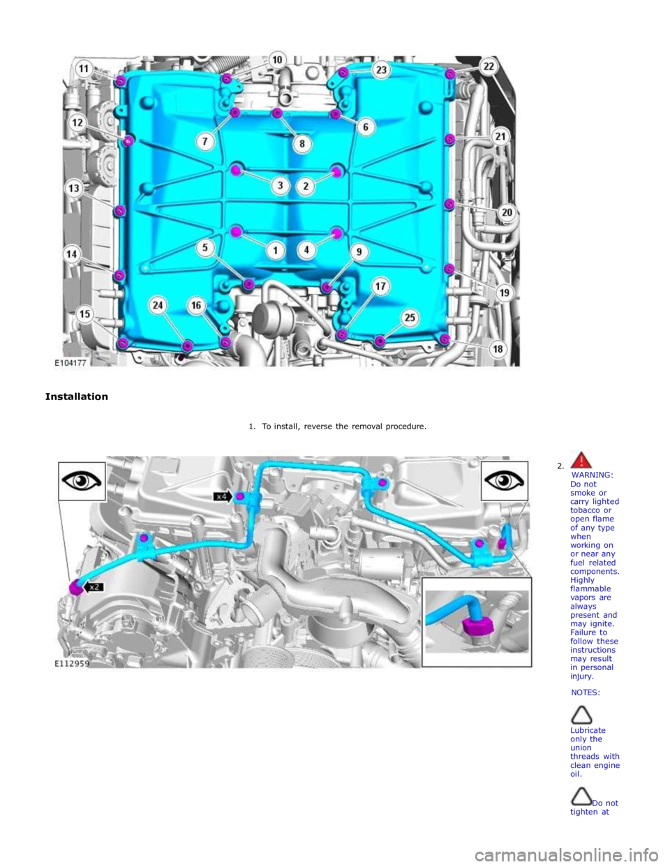
1. To install, reverse the removal procedure.
2.
WARNING:
Do not
smoke or
carry lighted
tobacco or
open flame
of any type
when
working on
or near any
fuel related
components.
Highly
flammable
vapors are
always
present and
may ignite.
Failure to
follow these
instructions
may result
in personal
injury.
NOTES:
Lubricate
only the
union
threads with
clean engine
oil.
Do not
tighten at
Page 1318 of 3039
this stage.
Remove and
discard the
blanking
caps.
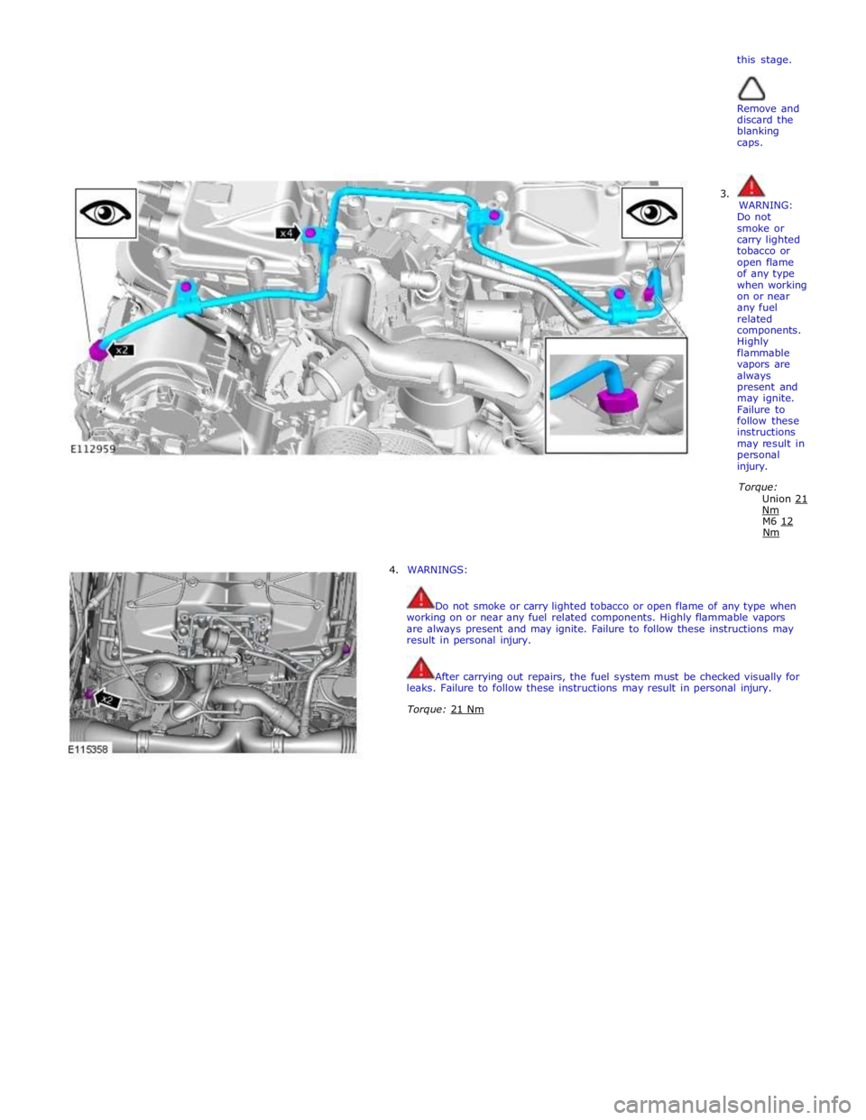
3.
WARNING:
Do not
smoke or
carry lighted
tobacco or
open flame
of any type
when working
on or near
any fuel
related
components.
Highly
flammable
vapors are
always
present and
may ignite.
Failure to
follow these
instructions
may result in
personal
injury.
Torque:
Union 21 Nm M6 12 Nm
4. WARNINGS:
Do not smoke or carry lighted tobacco or open flame of any type when
working on or near any fuel related components. Highly flammable vapors
are always present and may ignite. Failure to follow these instructions may
result in personal injury.
After carrying out repairs, the fuel system must be checked visually for
leaks. Failure to follow these instructions may result in personal injury.
Torque: 21 Nm
Page 1429 of 3039
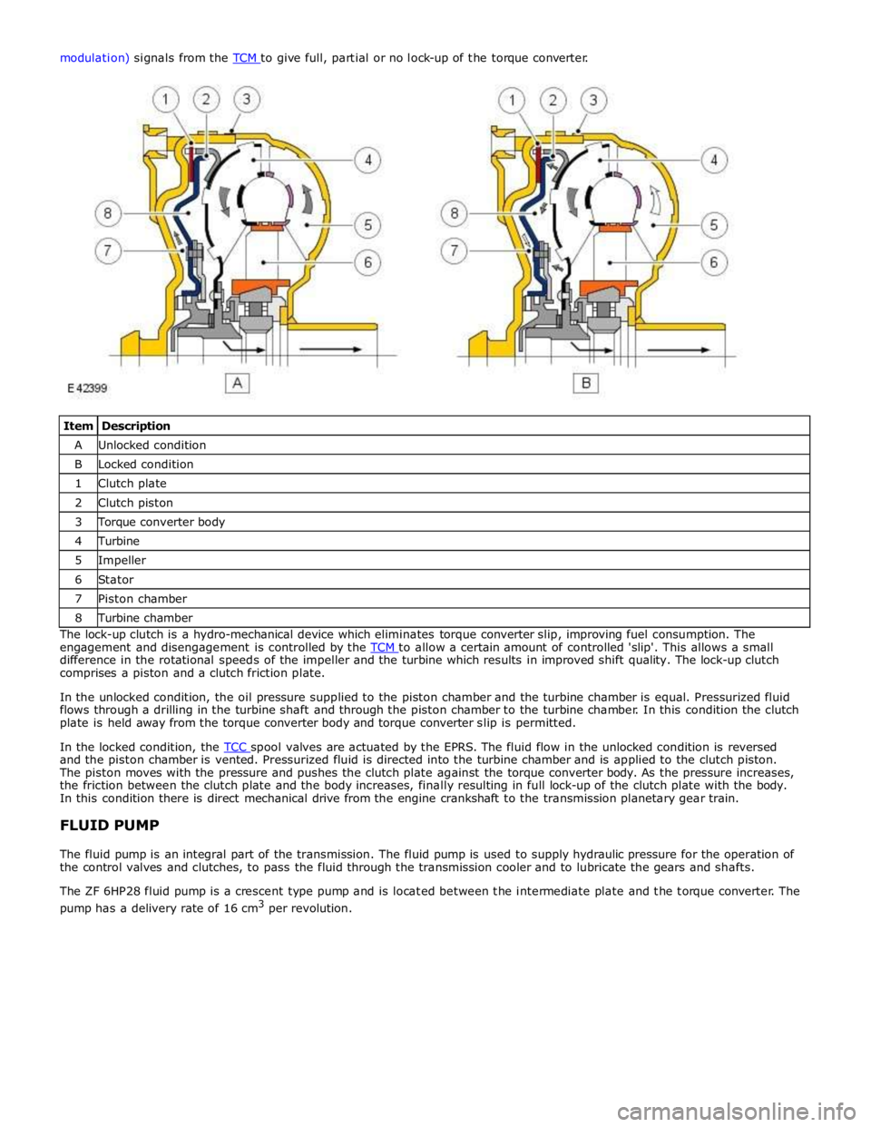
Item Description A Unlocked condition B Locked condition 1 Clutch plate 2 Clutch piston 3 Torque converter body 4 Turbine 5 Impeller 6 Stator 7 Piston chamber 8 Turbine chamber The lock-up clutch is a hydro-mechanical device which eliminates torque converter slip, improving fuel consumption. The
engagement and disengagement is controlled by the TCM to allow a certain amount of controlled 'slip'. This allows a small difference in the rotational speeds of the impeller and the turbine which results in improved shift quality. The lock-up clutch
comprises a piston and a clutch friction plate.
In the unlocked condition, the oil pressure supplied to the piston chamber and the turbine chamber is equal. Pressurized fluid
flows through a drilling in the turbine shaft and through the piston chamber to the turbine chamber. In this condition the clutch
plate is held away from the torque converter body and torque converter slip is permitted.
In the locked condition, the TCC spool valves are actuated by the EPRS. The fluid flow in the unlocked condition is reversed and the piston chamber is vented. Pressurized fluid is directed into the turbine chamber and is applied to the clutch piston.
The piston moves with the pressure and pushes the clutch plate against the torque converter body. As the pressure increases,
the friction between the clutch plate and the body increases, finally resulting in full lock-up of the clutch plate with the body.
In this condition there is direct mechanical drive from the engine crankshaft to the transmission planetary gear train.
FLUID PUMP
The fluid pump is an integral part of the transmission. The fluid pump is used to supply hydraulic pressure for the operation of
the control valves and clutches, to pass the fluid through the transmission cooler and to lubricate the gears and shafts.
The ZF 6HP28 fluid pump is a crescent type pump and is located between the intermediate plate and the torque converter. The
pump has a delivery rate of 16 cm3
per revolution.
Page 1573 of 3039
Fuel System - General Information - Spring Lock Couplings
General Procedures Published: 11-May-2011
Disconnect
1. WARNINGS:
Place the vehicle in a quarantined area and arrange "No
Smoking/Petrol Fumes" signs about the vehicle.
Before any work is carried out on the fuel system, ground the
vehicle to earth and maintain the ground connection until the work is
complete.
Do not smoke or carry lighted tobacco or open flame of any type
when working on or near any fuel related components. Highly flammable
vapors are always present and may ignite. Failure to follow these
instructions may result in personal injury.
The fuel system remains pressurized for a long time after the
ignition is switched off. The fuel pressure must be relieved before
attempting any repairs. Failure to follow these instructions may result in
personal injury.
After carrying out repairs, the fuel system must be checked visually
for leaks. Failure to follow these instructions may result in personal
injury.
This procedure involves fuel handling. Be prepared for fuel spillage
at all times and always observe fuel handling precautions. Failure to
follow these instructions may result in personal injury.
If taken internally do not induce vomiting, seek immediate medical
attention. Failure to follow these instructions may result in personal
injury.
If fuel contacts the eyes, flush the eyes with cold water or
eyewash solution and seek medical attention.
Wash hands thoroughly after handling, as prolonged contact may
cause irritation. Should irritation develop, seek medical attention.
Relieve the fuel system pressure. For additional information, refer to the
procedure in this section: Pressure Relief. Spring Lock Coupling Tool or Equivalent
310-D005 (23-040) Special Tool(s)
Page 1577 of 3039
Fuel System - General Information - Quick Release Coupling
General Procedures
Disconnect Published: 11-May-2011
1. WARNINGS:
Place the vehicle in a quarantined area and arrange "No
Smoking/Petrol Fumes" signs about the vehicle.
Before any work is carried out on the fuel system, ground the
vehicle to earth and maintain the ground connection until the work is
complete.
Do not smoke or carry lighted tobacco or open flame of any type
when working on or near any fuel related components. Highly flammable
vapors are always present and may ignite. Failure to follow these
instructions may result in personal injury.
The fuel system remains pressurized for a long time after the
ignition is switched off. The fuel pressure must be relieved before
attempting any repairs. Failure to follow these instructions may result in
personal injury.
After carrying out repairs, the fuel system must be checked visually
for leaks. Failure to follow these instructions may result in personal
injury.
This procedure involves fuel handling. Be prepared for fuel spillage
at all times and always observe fuel handling precautions. Failure to
follow these instructions may result in personal injury.
If taken internally do not induce vomiting, seek immediate medical
attention. Failure to follow these instructions may result in personal
injury.
If fuel contacts the eyes, flush the eyes with cold water or
eyewash solution and seek medical attention.
Wash hands thoroughly after handling, as prolonged contact may
cause irritation. Should irritation develop, seek medical attention.
Relieve the fuel system pressure. For additional information, refer to the
procedure in this section: Pressure Relief.
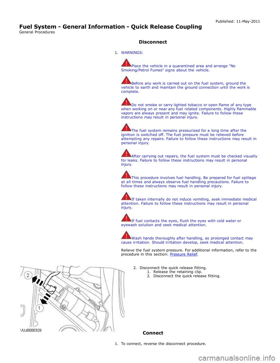
2. Disconnect the quick release fitting.
1. Release the retaining clip.
2. Disconnect the quick release fitting.
Connect
1. To connect, reverse the disconnect procedure.
Page 1578 of 3039
Published: 11-May-2011
Fuel System - General Information - Quick Release Coupling - Push Connect
General Procedures
Disconnect
1. WARNINGS:
Place the vehicle in a quarantined area and arrange "No
Smoking/Petrol Fumes" signs about the vehicle.
Before any work is carried out on the fuel system, ground the
vehicle to earth and maintain the ground connection until the work is
complete.
Do not smoke or carry lighted tobacco or open flame of any type
when working on or near any fuel related components. Highly flammable
vapors are always present and may ignite. Failure to follow these
instructions may result in personal injury.
The fuel system remains pressurized for a long time after the
ignition is switched off. The fuel pressure must be relieved before
attempting any repairs. Failure to follow these instructions may result in
personal injury.
After carrying out repairs, the fuel system must be checked visually
for leaks. Failure to follow these instructions may result in personal
injury.
This procedure involves fuel handling. Be prepared for fuel spillage
at all times and always observe fuel handling precautions. Failure to
follow these instructions may result in personal injury.
If taken internally do not induce vomiting, seek immediate medical
attention. Failure to follow these instructions may result in personal
injury.
If fuel contacts the eyes, flush the eyes with cold water or
eyewash solution and seek medical attention.
Wash hands thoroughly after handling, as prolonged contact may
cause irritation. Should irritation develop, seek medical attention.
Relieve the fuel system pressure. For additional information, refer to the
procedure in this section:
For additional information, refer to: Fuel System Pressure Release
(310-00 Fuel System - General Information, General Procedures).
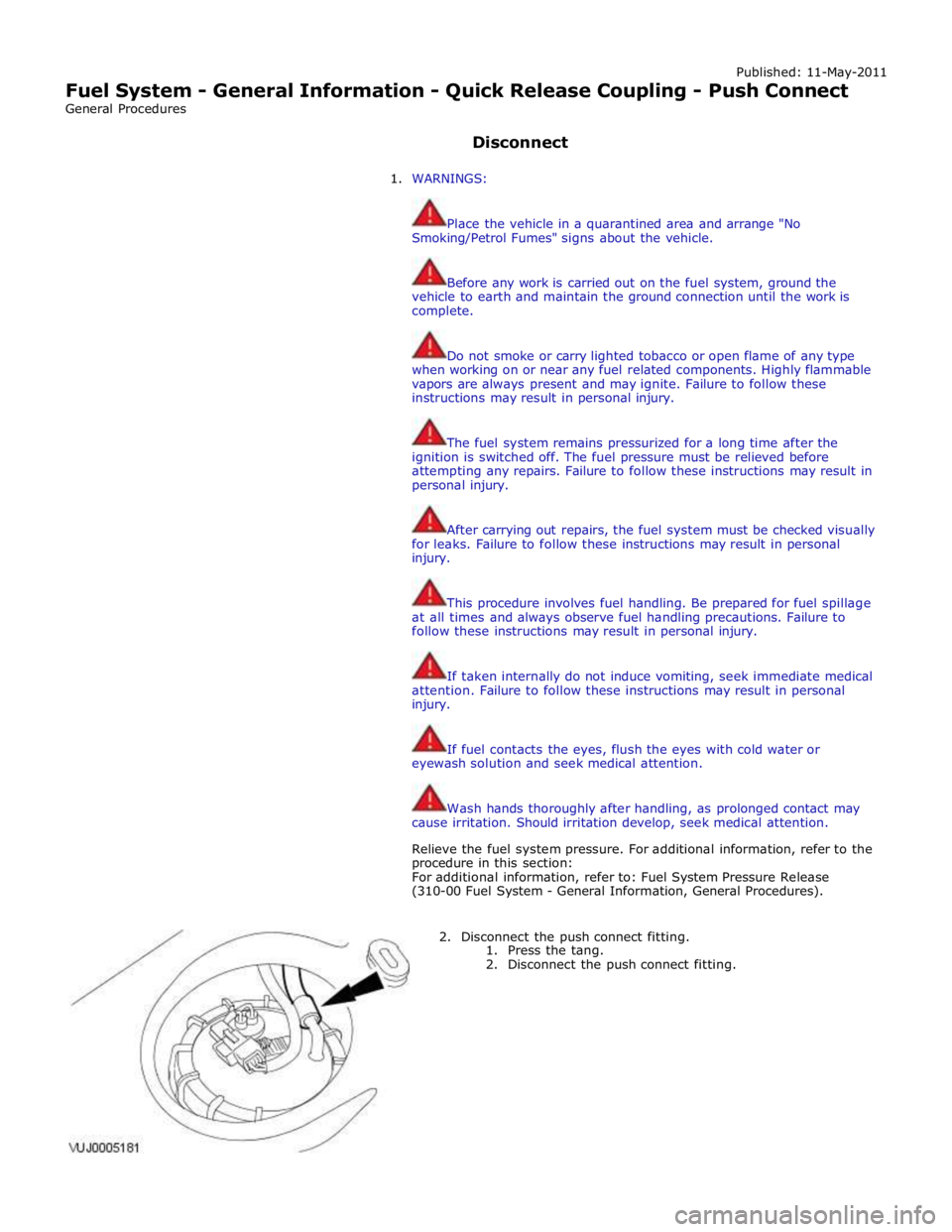
2. Disconnect the push connect fitting.
1. Press the tang.
2. Disconnect the push connect fitting.
Page 1586 of 3039
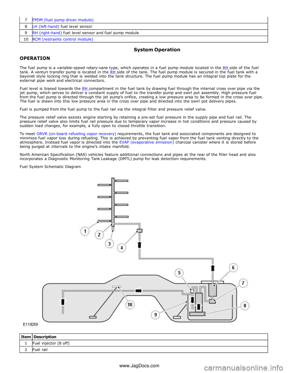
8 LH (left-hand) fuel level sensor 9 RH (right-hand) fuel level sensor and fuel pump module 10 RCM (restraints control module)
OPERATION System Operation
The fuel pump is a variable-speed rotary-vane type, which operates in a fuel pump module located in the RH side of the fuel tank. A venturi transfer pump is located in the RH side of the tank. The fuel pump module is secured in the fuel tank with a bayonet style locking ring that is welded into the tank structure. The fuel pump module has an integral top plate for the
external pipe work and electrical connectors.
Fuel level is biased towards the RH compartment in the fuel tank by drawing fuel through the internal cross over pipe via the jet pump, which serves to deliver a constant supply of fuel to the transfer pump and swirl pot assembly. High pressure fuel
from the fuel pump is directed through the jet pump's orifice, creating a low pressure area to be formed in the cross over pipe.
The fuel is drawn into this low pressure area in the cross over pipe and directed into the swirl pot delivery pipes.
Fuel is pumped from the fuel pump to the fuel rail via the integral filter and pressure relief valve.
The pressure relief valve assists engine starting by retaining a pre-set fuel pressure in the supply pipe and fuel rail. The
pressure relief valve also limits fuel rail pressure due to temporary vapor increase in hot conditions and pressure caused by
sudden load changes, for example, a fully open to closed throttle transition.
To meet ORVR (on-board refueling vapor recovery) requirements, the fuel tank and associated components are designed to
minimize fuel vapor loss during refueling. This is achieved by preventing fuel vapor from the fuel tank venting directly to the
atmosphere. Instead fuel vapor is directed into the EVAP (evaporative emission) charcoal canister where it is stored before
being purged at intervals to the engine’s intake manifold.
North American Specification (NAS) vehicles feature additional connections and pipes at the rear of the filler head and also
incorporates a Diagnostic Monitoring Tank Leakage (DMTL) pump for leak detection requirements.
Fuel System Schematic Diagram
Item Description 1 Fuel injector (8 off) 2 Fuel rail www.JagDocs.com
Page 1588 of 3039
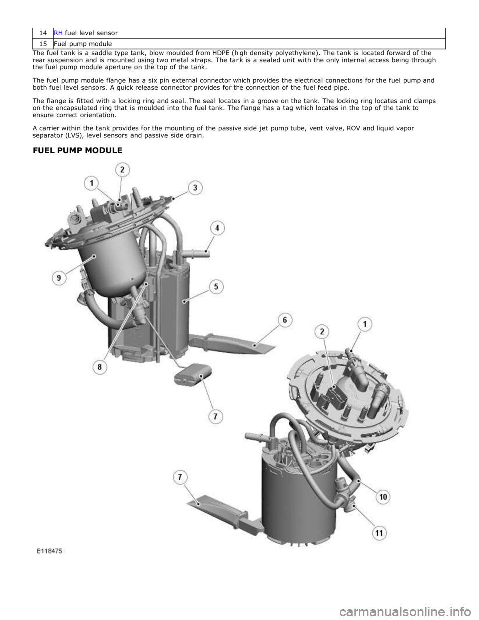
15 Fuel pump module The fuel tank is a saddle type tank, blow moulded from HDPE (high density polyethylene). The tank is located forward of the
rear suspension and is mounted using two metal straps. The tank is a sealed unit with the only internal access being through
the fuel pump module aperture on the top of the tank.
The fuel pump module flange has a six pin external connector which provides the electrical connections for the fuel pump and
both fuel level sensors. A quick release connector provides for the connection of the fuel feed pipe.
The flange is fitted with a locking ring and seal. The seal locates in a groove on the tank. The locking ring locates and clamps
on the encapsulated ring that is moulded into the fuel tank. The flange has a tag which locates in the top of the tank to
ensure correct orientation.
A carrier within the tank provides for the mounting of the passive side jet pump tube, vent valve, ROV and liquid vapor
separator (LVS), level sensors and passive side drain.
FUEL PUMP MODULE