2010 JAGUAR XFR door lock
[x] Cancel search: door lockPage 1832 of 3039
Warning Devices - Blindspot Monitoring System - Overview
Description and Operation
OVERVIEW Published: 11-May-2011
Eliminating blind spots is a major element in vehicle body design, but because of the structural requirements of B, C and D
posts, blind spots cannot be entirely eliminated. Statistics show that some accidents are directly attributable to drivers moving
across into the path of overtaking vehicles that have not been seen in conventional mirrors. New mirror designs have improved
the situation, but by remotely covering areas that cannot be seen either directly or by the vehicle mirrors, have led to the
introduction of a radar-based blind spot monitoring system.
The blind spot monitoring system comprises:
LH (left-hand) Blind spot monitoring sensor
RH (right-hand) Blind spot monitoring sensor
LH door mirror RH door mirror
The system uses two radar modules operating at a frequency of 24 GHz and each combining the radar face and electronic
module in a single unit. The modules are located behind the rear bumper surface, symmetrically, one on each side of the car
behind the rear wheels. They are side facing and inclined rearwards at an angle of 16 degrees, which is dictated by the shape
at the rear of the vehicle. Each module is calibrated to detect a vehicle in the driver’s blind spot. Once a vehicle is detected
the module illuminates an amber warning ‘alert icon’ LED (light emitting diode) in the relevant exterior door mirror. If there is a
fault or blockage with the blind spot monitoring system an amber warning indicator dot LED is displayed in the exterior mirror and the message ‘blind spot monitoring not available’ is displayed in the instrument cluster message center.
When the system initiates, it performs a self-check, during which the warning icons in the mirrors illuminate alternately for a
short period of time. Each module does a left/right determination check when the ignition is switched on. Each mirror has a
different circuit configuration so that the modules can determine which mirror they are connected to. If a module detects the
wrong mirror it will go into a fault condition.
The blind spot monitoring modules receive vehicle speed on the medium speed CAN (controller area network) and are inactive
until the vehicle reaches 16kph (10mph). Each blind spot monitor module emits a radar field greater than the blind spot area.
Each Blind Spot Monitor module emits a radar field greater than the blind spot area. The actual blind spot area is calibrated
into the module during its manufacture.
CAUTION: The blind spot monitoring system is designed as a driver aid not a safety device. The driver should always
exercise due care and attention whilst driving. www.JagDocs.com
Page 1834 of 3039
Blind Spot Monitoring System Operation
The purpose of the blind spot monitoring system is to detect an object moving with a positive velocity relative to the radar
module, on either side of the vehicle, at a distance of up to 2.5 meters laterally and in an area from the door mirror up to 7.0
meters behind the module. These criteria identify an overtaking vehicle within the blind-spot area and within a typical
carriageway lane width, while eliminating other objects that are not relevant, either because of their position, they are
stationary, traveling in the opposite direction, or being overtaken. A vehicle is classed as a heavy goods vehicle, car or
motorcycle. A motorcycle is defined as a minimum size of 2.0m long, 0.8m wide (widest point) and 1.1m high. The system is
not affected by the mass of the overtaking vehicle providing all identification criteria, including relative velocity of (16km/h -
10mph) or above, is met.
The system emits radar pulses and analyses the reflections, identifying anything that moves into the blind spot zone. Having
detected another vehicle in the defined blind spot zone it alerts the driver by illuminating the amber alert icon located in the
appropriate exterior mirror.
NOTE: If an overtaking vehicle is detected on both sides of the vehicle simultaneously, the warning alert icons in both
mirrors will illuminate.
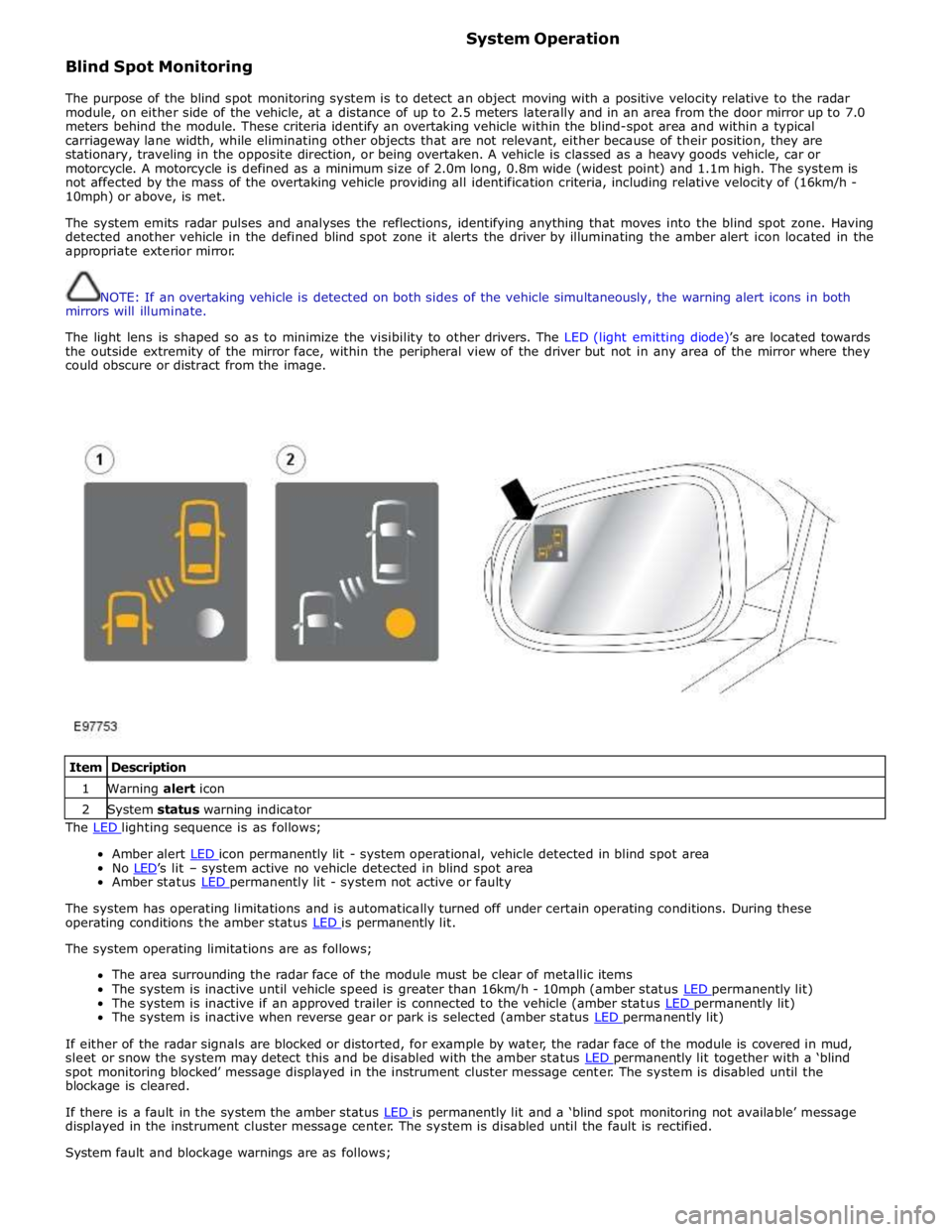
The light lens is shaped so as to minimize the visibility to other drivers. The LED (light emitting diode)’s are located towards
the outside extremity of the mirror face, within the peripheral view of the driver but not in any area of the mirror where they
could obscure or distract from the image.
Item Description 1 Warning alert icon 2 System status warning indicator The LED lighting sequence is as follows;
Amber alert LED icon permanently lit - system operational, vehicle detected in blind spot area No LED’s lit – system active no vehicle detected in blind spot area Amber status LED permanently lit - system not active or faulty
The system has operating limitations and is automatically turned off under certain operating conditions. During these
operating conditions the amber status LED is permanently lit. The system operating limitations are as follows;
The area surrounding the radar face of the module must be clear of metallic items
The system is inactive until vehicle speed is greater than 16km/h - 10mph (amber status LED permanently lit) The system is inactive if an approved trailer is connected to the vehicle (amber status LED permanently lit) The system is inactive when reverse gear or park is selected (amber status LED permanently lit)
If either of the radar signals are blocked or distorted, for example by water, the radar face of the module is covered in mud,
sleet or snow the system may detect this and be disabled with the amber status LED permanently lit together with a ‘blind spot monitoring blocked’ message displayed in the instrument cluster message center. The system is disabled until the
blockage is cleared.
If there is a fault in the system the amber status LED is permanently lit and a ‘blind spot monitoring not available’ message displayed in the instrument cluster message center. The system is disabled until the fault is rectified.
System fault and blockage warnings are as follows;
Page 1871 of 3039

Published: 21-Dec-2012
Battery and Charging System - General Information - Quiescent Drain
Description and Operation
VEHICLE QUIESCENT CURRENT TESTING
On vehicles fitted with a Battery Monitoring System (BMS), the diagnostic routine for quiescent drain testing in the approved
Jaguar or Land Rover diagnostic system should be utilized.
If a customer complains of a vehicle battery that discharges continuously or when left for a prolonged period of time, it is
recommended that a quiescent drain test is performed as described below.
The battery drain should be measured using the approved Jaguar or Land Rover diagnostic system or a Digital Multi-Meter
(DVOM). A procedure for quiescent drain measurement using the diagnostic system is available in the Diagnosis and Testing
section of the Workshop Manual. The vehicle should be in the locked/armed state (for example vehicle alarm fully armed), all
doors, engine and luggage compartment lids are open and latched (so as to appear closed from an electrical point of view).
The test should take place after the vehicle has entered shutdown mode. The time taken for this to occur after the ignition is
switched off varies according to model (Refer to the Topix On line resource for details).
When the vehicle is armed, the effect of the security system Light Emitting Diode (LED) flashing is to cause a pulsation in the
measured current drain. In this case, either the average current should be taken (using a Digital Multi- Meter (DVOM) with an
averaging system) or the current reading taken, ignoring the brief high current peaks.
EQUIPMENT
Approved Jaguar or Land Rover diagnostic system with current probeOR Digital Multi-Meter (DVOM) with current probe.
METHOD OF MEASUREMENT
Using an Approved Jaguar or Land Rover Diagnostic System.
1. Switch off all electrical loads and ensure that the ignition is off
2. Connect the current probe to the approved Jaguar or Land Rover diagnostic system
3. Calibrate the probe
4. Install a clamp around the battery lead/junction box lead
5. Go to the Quiescent Current Testing section in this procedure
Using a digital multimeter
Do not use an in-line DVOM to measure the quiescent drain on vehicles fitted with an electronic throttle (for example XK 2006
onwards). The current exceeds the maximum amount the fuse in the DVOM is capable of handling.
1. Switch off all electrical loads and ensure that the ignition is off
2. Connect the current probe to the digital multmeter
3. Calibrate the probe
4. Install a clamp around the battery lead/junction box lead
5. Go to the Quiescent Current Testing section in this procedure
QUIESCENT CURRENT TESTING
1. Switch ignition to ‘on’ or select ignition mode in keyless vehicles and switch to ‘off’ (do not crank)
2. Remove key from ignition switch (if equipped)
3. Open and latch all doors, hood and luggage compartment lid
4. Lock the vehicle using the remote function on the remote handset. (Single lock only to avoid volumetric alarm arming)
5. Remove any other potential electrical drains such as accessories plugged into accessory sockets
6. Record the amperage readings after the shutdown period referenced in the Topix on line resource for details. Note all
cars from 10MY onwards and XK from 07MY and XF from 08MY should be less than 30mA after 30 minutes
7. Record the final reading on the battery report form
The preferred method of testing following an excessive current consumption figure is to use a current probe around individual
junction box leads to the various suspected circuits to identify a potential cause. This is in preference to the old method of
removing fuses for the following reasons:
The drain may be caused by a module remaining active and preventing the quiescent drain from reducing to normal
levels
The drain may be caused by a relay winding that is activated. Pulling the fuse can allow this to ‘reset’ and the drain will
be lost and go un-diagnosed
QUIESCENT DRAIN - TYPICAL VALUES
NOTE: The quiescent drain after the initial shutdown period should not exceed the value shown in the table.
Jaguar Quiescent Drain Values
MODEL SHUT DOWN PERIOD (minutes) TYPICAL VALUES BATTERY DRAIN (mA) XJS 3.2 60 <30 Sovereign 3.2 60 <37.3
Page 1903 of 3039
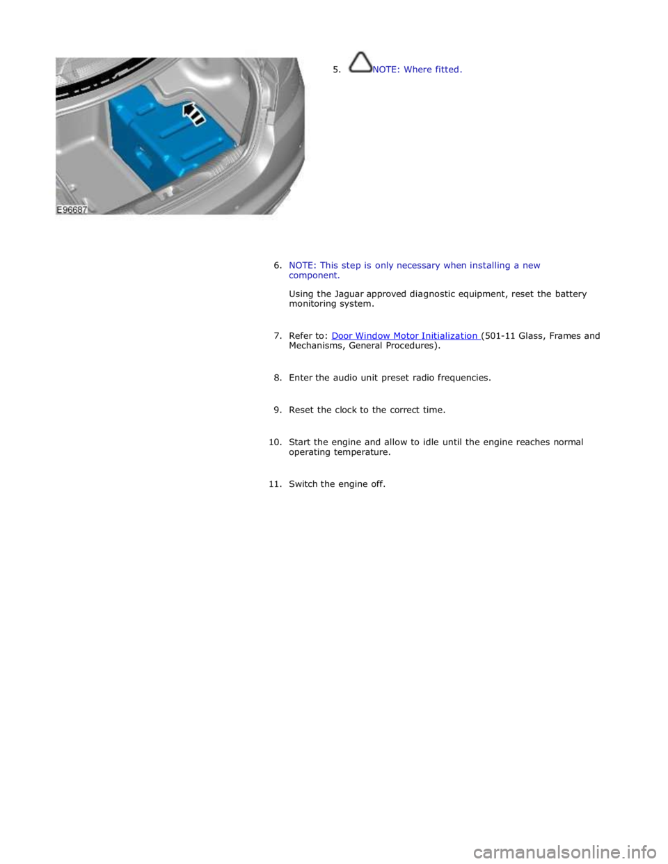
5. NOTE: Where fitted.
6. NOTE: This step is only necessary when installing a new
component.
Using the Jaguar approved diagnostic equipment, reset the battery
monitoring system.
7. Refer to: Door Window Motor Initialization (501-11 Glass, Frames and Mechanisms, General Procedures).
8. Enter the audio unit preset radio frequencies.
9. Reset the clock to the correct time.
10. Start the engine and allow to idle until the engine reaches normal
operating temperature.
11. Switch the engine off.
Page 1907 of 3039
Installation
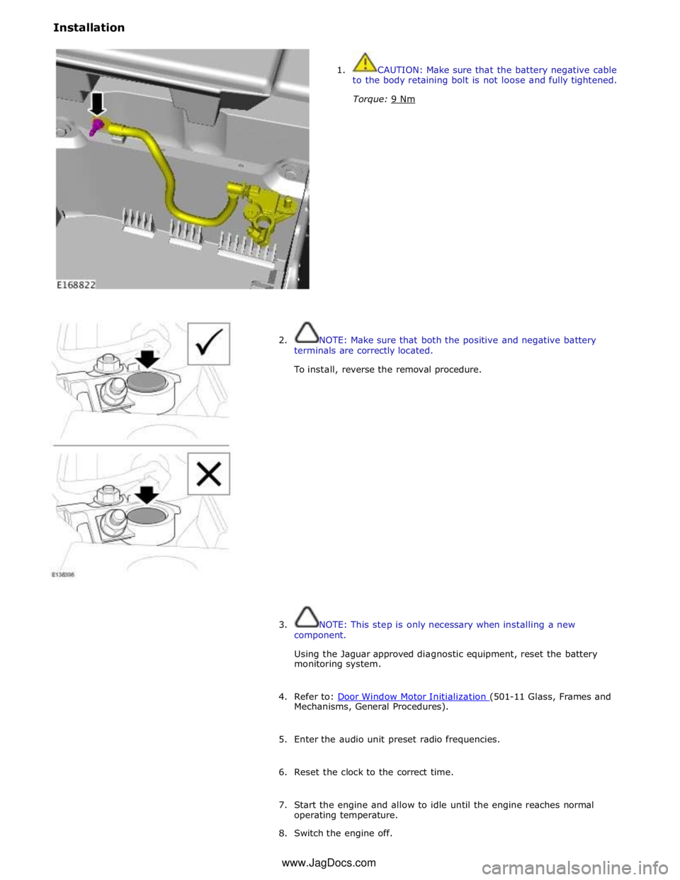
1. CAUTION: Make sure that the battery negative cable
to the body retaining bolt is not loose and fully tightened.
Torque: 9 Nm
2. NOTE: Make sure that both the positive and negative battery
terminals are correctly located.
To install, reverse the removal procedure.
3. NOTE: This step is only necessary when installing a new
component.
Using the Jaguar approved diagnostic equipment, reset the battery
monitoring system.
4. Refer to: Door Window Motor Initialization (501-11 Glass, Frames and Mechanisms, General Procedures).
5. Enter the audio unit preset radio frequencies.
6. Reset the clock to the correct time.
7. Start the engine and allow to idle until the engine reaches normal
operating temperature.
8. Switch the engine off. www.JagDocs.com
Page 2027 of 3039
by Field Effect Transistors (FET's). The FET's can detect overloads and short circuits and respond to heat generated by
increased current flow caused by a short circuit.
On a normal conventionally protected circuit this would cause a fuse to blow. The FET's respond to the heat increase and
disconnect the power supply to the affected circuit. When the fault is rectified or the FET has cooled, the FET will reset and
operate the circuit normally. If the fault persists the FET will cycle, disconnecting and reconnecting the power supply.
The CJB and the RJB store fault codes which can be retrieved using a Jaguar approved diagnostic system. The fault code will identify that there is a fault on a particular output circuit which will assist with fault diagnosis and detection.
Alarm Indications
The exterior lighting system is used for alarm arm and disarm requests to show alarm system status.
When the driver locks and arms the vehicle, a visual indication of a successful lock and arm request is displayed to the driver
by a single flash of the hazard flashers. If the vehicle is superlocked, then the hazard flashers will flash a second time (200 ms
off and 200 ms on) to confirm the superlock request.
If the alarm is activated, the hazard flashers are operated for 10, 30 second cycles of 200 ms on and 200 ms off, with a 10
second delay between each cycle.
NOTE: On North American Specification (NAS) vehicles, the delay between the cycle when the alarm is activated is 60
seconds.
Lights on Warning
When the ignition is in the off power mode 0 or accessory power mode 4 and the lighting control switch is in the side lamp or
headlamp position, a warning chime will sound if the driver's door is opened. This indicates to the driver that the exterior
lights have been left switched on.
The chime is generated from the instrument cluster sounder on receipt of a lights on signal, a driver's door open signal and an
ignition off power mode 0 or accessory power mode 4 signal via a medium speed CAN bus signal from the CJB. Headlamp Timer
The RJB controls the headlamp timer function which allows the headlamps to remain on for a period of time after leaving the vehicle. This is a driver convenience feature which illuminates the driveway after leaving the vehicle.
To operate the timer function the lighting control switch must be in one of the three headlamp timer positions when the
ignition status is changed from ignition on power mode 6 to the off power mode 0. The timer function will then be initiated and
the low beam headlamps will be illuminated for the selected timer period.
NOTE: If the lighting switch is in the AUTO position, the headlamp timer will not function when the ignition is changed to
off power mode 0.
When the lighting control switch is in the autolamp exit delay position, the lighting control switch reference voltage flows
through 4 of the resistors. The returned signal voltage is detected by the instrument cluster which outputs a message on the
medium speed CAN bus to the RJB that autolamps has been selected.
Depending on the selected exit delay position, the reference voltage to the autolamp exit delay switch is routed through 3, 2
or 1 resistors which is detected by the instrument cluster. The cluster outputs a message on the medium speed CAN bus to the RJB that autolamp exit delay period has been selected at 30, 60 or 120 seconds respectively. Crash Signal Activation
When a crash signal is transmitted from the RCM (restraints control module), the RJB activates the hazard flashers. The hazard flashers continue to operate until the ignition is in the off power mode 0 or accessory power mode 6. Once this ignition state
has occurred, the RCM will cease to transmit the crash signal.
LIGHTING CONTROL SWITCH
The instrument cluster outputs 2 reference voltages to the rotary lighting control switch; one feed being supplied to the light
selection function of the switch and the second feed being supplied to the auto headlamp exit delay function. The switch
position is determined by instrument cluster by the change in returned signal voltage which is routed through up to 4 resistors
in series depending on the selection made.
OFF - When the lighting control switch is in the off position, the reference voltage flows through 1 of the resistors. The
returned signal voltage is detected by the instrument cluster which outputs a message on the medium speed CAN bus to the CJB that no lighting selection is made. The reference voltage to the auto headlamp exit delay switch is routed through 4 resistors which is detected by the instrument cluster which outputs a message on the medium speed CAN bus to the CJB that auto headlamp or exit delay has not been selected.
SIDE LAMPS - When the lighting control switch is in the side lamp position, the reference voltage flows through 2 of the
resistors. The returned signal voltage is detected by the instrument cluster which outputs a message on the medium speed
CAN bus to the CJB to activate the side lamps. The reference voltage to the autolamp exit delay switch is routed through 4 resistors which is detected by the instrument cluster which outputs a message on the medium speed CAN bus to the CJB that auto headlamp or exit delay has not been selected.
HEADLAMPS - When the lighting control switch is in the headlamp position, the reference voltage flows through 3 of the
Page 2055 of 3039
Interior Lighting - Interior Lighting - Overview
Description and Operation
OVERVIEW Published: 11-May-2011
Interior lighting is provided to enable the safe entry and departure from the vehicle for the driver and passengers in low
ambient light conditions, without any manual switching of the lights.
NOTE: The term interior lamps also includes the door mirror approach lamps.
The interior lamps are controlled by the CJB (central junction box) and the RJB (rear junction box) and have 2 modes of
operation: manual and automatic. The front interior lamps in the front overhead console are operated using the 'JaguarSense'
system. The system uses capacitive proximity sensor technology for the switch operation which is integral with the overhead
console. The rear overhead console interior lamps have conventional switches.
In the manual mode the interior lamps can be switched on and off with the JaguarSense system. Positioning your hand
adjacent to each lamp in the front overhead console will switch interior lamps on or off and completely disable the interior
lamp system. In the automatic mode the interior lamp functionality is controlled by the CJB and the RJB and reacts to the vehicle being locked or unlocked and opening the vehicle doors.
In manual mode the interior lamps can be operated by placing your finger(s) close to, or touch, the surface of the appropriate
lamp. The courtesy light and map reading lamps can be operated manually by the 'JaguarSense' system. When in automatic
mode, the courtesy lamp functionality is also controlled by the CJB and the RJB and reacts to the vehicle being locked or unlocked and opening the vehicle doors. To deactivate or activate automatic illumination, touch the front courtesy lamp for
approximately 2 seconds
The driver's and passenger door approach lamps are controlled by the driver's door module and the passenger door module
respectively and operate with the automatic mode. The door modules receive a power supply from the RJB and receive information to illuminate the approach lamps on the medium speed CAN (controller area network) bus from the RJB and the CJB. www.JagDocs.com
Page 2058 of 3039
3 BJB - Megafuse 4 RJB 5 Glovebox lamp 6 Glovebox lamp switch 7 LH footwell lamp 8 RH footwell lamp 9 LH vanity mirror 10 RH vanity mirror 11 LH rear interior lamp 12 RH rear interior lamp 13 CJB 14 Ambience lighting LED's 15 LH map reading lamp 16 Courtesy lamp 17 RH map reading lamp
JUNCTION BOXES
Inputs System Operation
The CJB receives the following inputs which affect the operation of the interior lamps: Ignition mode
Lock/unlock
Luggage compartment lid latch switch
Door latch switches.
Outputs
The RJB outputs the following for the interior lighting system: Luggage compartment lamp power supply
Driver and passenger door module power supplies
Fade on and off grounds for front and rear overhead console interior lamps and footwell lamps
PWM (pulse width modulation) power output for the ambience lighting.
Interior Lamp Time-Out
The interior lamps are controlled by a timer within the CJB which allows a 60 second delay period for the lamps to remain active after the ignition mode has been changed to off power mode 0 or the vehicle has been unlocked. The interior lamp fade
off is controlled by the RJBvia a delayed power off relay in the CJB. The following interior lamps are subject to the delay period:
Front overhead console interior lamp
Rear interior lamps
Footwell lamps
Door mirror approach lamps.
The timer delay is activated when the CJB receives one of the following signals: An unlock signal from the Smart Key via the keyless vehicle module.
Ignition mode is changed from the crank power mode 9 or ignition power mode 6 to the accessory power mode 4 to the
off power mode 0.
If a second occurrence of the above actions occurs within the timer period, the timer will be rest and the delay period timer will
restart.
The timer delay is deactivated when the CJB receives one of the following signals: A lock signal from the Smart Key via the keyless vehicle module
Ignition mode is changed from the off power mode 0 to the accessory power mode 4 or ignition power mode 6
The CJB receives a door opened signal (even if that door is subsequently closed). Battery Saver
The battery saver provides an automatic shut-off of the interior lamps after a period of 15 minutes in order to prevent
excessive power drain on the battery.
When the ignition mode is changed from the ignition power mode 6 or accessory power mode 4 to the off power mode 0, the
CJB starts a timer which de-energizes a delayed power off relay in the CJB, removing the power supply to the interior lamps after a period of 15 minutes, switching off all or any interior lamps which have remained on for any reason.