2010 JAGUAR XFR door lock
[x] Cancel search: door lockPage 2059 of 3039

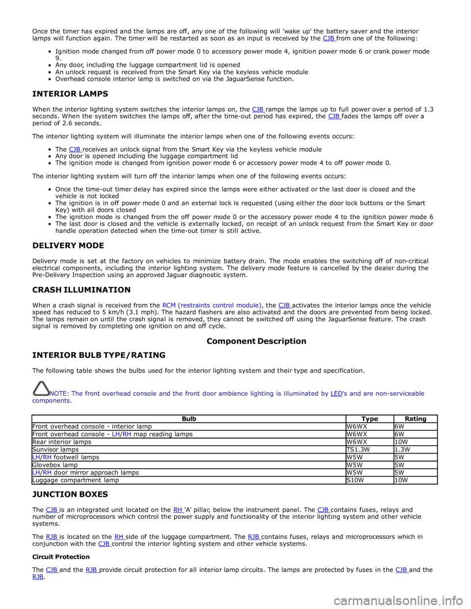
Once the timer has expired and the lamps are off, any one of the following will 'wake up' the battery saver and the interior
lamps will function again. The timer will be restarted as soon as an input is received by the CJB from one of the following:
Ignition mode changed from off power mode 0 to accessory power mode 4, ignition power mode 6 or crank power mode
9.
Any door, including the luggage compartment lid is opened
An unlock request is received from the Smart Key via the keyless vehicle module
Overhead console interior lamp is switched on via the JaguarSense function.
INTERIOR LAMPS
When the interior lighting system switches the interior lamps on, the CJB ramps the lamps up to full power over a period of 1.3 seconds. When the system switches the lamps off, after the time-out period has expired, the CJB fades the lamps off over a period of 2.6 seconds.
The interior lighting system will illuminate the interior lamps when one of the following events occurs:
The CJB receives an unlock signal from the Smart Key via the keyless vehicle module Any door is opened including the luggage compartment lid
The ignition mode is changed from ignition power mode 6 or accessory power mode 4 to off power mode 0.
The interior lighting system will turn off the interior lamps when one of the following events occurs:
Once the time-out timer delay has expired since the lamps were either activated or the last door is closed and the
vehicle is not locked
The ignition is in off power mode 0 and an external lock is requested (using either the door lock buttons or the Smart
Key) with all doors closed
The ignition mode is changed from the off power mode 0 or the accessory power mode 4 to the ignition power mode 6
The last door is closed and the vehicle is externally locked, on receipt of an unlock request from the Smart Key or door
handle operation detected when the time-out timer is still active.
DELIVERY MODE
Delivery mode is set at the factory on vehicles to minimize battery drain. The mode enables the switching off of non-critical
electrical components, including the interior lighting system. The delivery mode feature is cancelled by the dealer during the
Pre-Delivery Inspection using an approved Jaguar diagnostic system.
CRASH ILLUMINATION
When a crash signal is received from the RCM (restraints control module), the CJB activates the interior lamps once the vehicle speed has reduced to 5 km/h (3.1 mph). The hazard flashers are also activated and the doors are prevented from being locked.
The lamps remain on until the crash signal is removed, they cannot be switched off using the JaguarSense feature. The crash
signal is removed by completing one ignition on and off cycle.
INTERIOR BULB TYPE/RATING Component Description
The following table shows the bulbs used for the interior lighting system and their type and specification.
NOTE: The front overhead console and the front door ambience lighting is illuminated by LED's and are non-serviceable components.
Bulb Type Rating Front overhead console - interior lamp W6WX 6W Front overhead console - LH/RH map reading lamps W6WX 6W Rear interior lamps W6WX 10W Sunvisor lamps TS1.3W 1.3W LH/RH footwell lamps W5W 5W Glovebox lamp W5W 5W LH/RH door mirror approach lamps W5W 5W Luggage compartment lamp S10W 10W JUNCTION BOXES
The CJB is an integrated unit located on the RH 'A' pillar, below the instrument panel. The CJB contains fuses, relays and number of microprocessors which control the power supply and functionality of the interior lighting system and other vehicle
systems.
The RJB is located on the RH side of the luggage compartment. The RJB contains fuses, relays and microprocessors which in conjunction with the CJB control the interior lighting system and other vehicle systems. Circuit Protection
The CJB and the RJB provide circuit protection for all interior lamp circuits. The lamps are protected by fuses in the CJB and the RJB.
Page 2069 of 3039

5 RJB (rear junction box) 6 Battery monitoring system module 7 Rear view camera 8 TCM (transmission control module) 9 Generator 10 Driver's door switch pack 11 Rear door control module 12 Driver's door control module 13 ECM (engine control module) 14 Electronic transmission selector 15 Driver's seat module 16 Driver's seat switch pack 17 Rear door control module 18 Front passenger door control module 19 Clockspring 20 Audio and telephone steering wheel switches 21 Instrument cluster 22 Start control module
Page 2072 of 3039

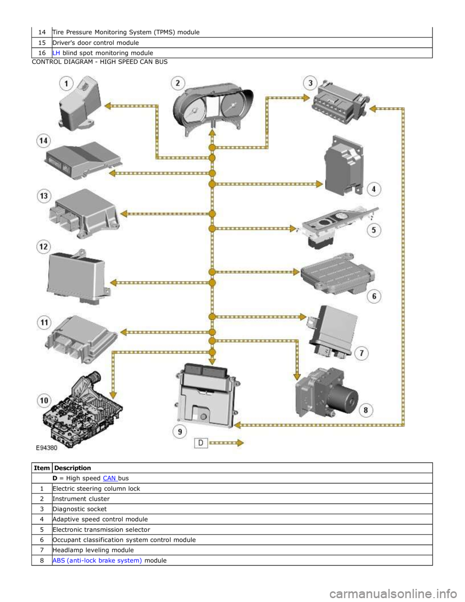
Tire Pressure Monitoring System (TPMS) module 15 Driver's door control module 16 LH blind spot monitoring module CONTROL DIAGRAM - HIGH SPEED CAN BUS
Item Description D = High speed CAN bus 1 Electric steering column lock 2 Instrument cluster 3 Diagnostic socket 4 Adaptive speed control module 5 Electronic transmission selector 6 Occupant classification system control module 7 Headlamp leveling module 8 ABS (anti-lock brake system) module
Page 2089 of 3039

DTC Description Possible Cause Action B115B11 Driver Seat Heater
Driver seat heater supply circuit
- short to ground Carry out any pinpoint tests associated with this DTC
using the manufacturer approved diagnostic system.
Refer to the electrical circuit diagrams and check driver
seat heater supply circuit for short to ground B115B15 Driver Seat Heater
Driver seat heater supply circuit
- short to power, open circuit Carry out any pinpoint tests associated with this DTC
using the manufacturer approved diagnostic system.
Refer to the electrical circuit diagrams and check driver
seat heater supply circuit for short to power, open circuit B117513
Driver Door Ajar
Switch
Driver door ajar switch signal
circuit - open circuit Refer to the electrical circuit diagrams and check driver
door ajar switch signal circuit for open circuit B117613
Passenger Door
Ajar Switch
Passenger door ajar switch
signal circuit - open circuit Refer to the electrical circuit diagrams and check
passenger door ajar switch signal circuit for open circuit B117712
Screenwash Level
Switch
Screenwash level switch signal
circuit - short to power Refer to the electrical circuit diagrams and check
screenwash level switch signal circuit for short to power B11C013
Driver Side Rear
Door Ajar Switch
Left rear door ajar switch signal
circuit - open circuit Refer to the electrical circuit diagrams and check left rear
door ajar switch signal circuit for open circuit B11C113
Passenger Side
Rear Door Ajar
Switch
Right rear door ajar switch
signal circuit - open circuit Refer to the electrical circuit diagrams and check right
rear door ajar switch signal circuit for open circuit B122223
Master Lock/Unlock
Switch
Master lock or unlock switch
digital input circuit - signal
stuck low Refer to the electrical circuit diagrams and check master
lock and unlock switch digital input circuits for short to
ground, open circuit B123711
Gear Shift Module
Early Wake-up
Transmission shift module
wake-up control circuit - short
to ground Carry out any pinpoint tests associated with this DTC
using the manufacturer approved diagnostic system.
Refer to the electrical circuit diagrams and check
transmission shift module wake-up control circuit for
short to ground B123712
Gear Shift Module
Early Wake-up
Transmission shift module
wake-up control circuit - short
to power Refer to the electrical circuit diagrams and check
transmission shift module wake-up control circuit for
short to power B123713
Gear Shift Module
Early Wake-up
Transmission shift module
wake-up control circuit - open
circuit Refer to the electrical circuit diagrams and check
transmission shift module wake-up control circuit for
open circuit B123E13 Crank Enable
OK to crank signal circuit -
open circuit Refer to the electrical circuit diagrams and check OK to
crank signal circuit for open circuit B1A8596
Ambient Light
Sensor
Light sensor internal electronic
failure Check and install a new sensor as required B1C4513
Front Wiper Park
Position Switch
Windshield wiper motor park
switch signal circuit - open
circuit Refer to the electrical circuit diagrams and check
windshield wiper motor park switch signal circuit for open
circuit B1C4523
Front Wiper Park
Position Switch
Signal stuck low Refer to the electrical circuit diagrams and check front
wiper park position switch input circuit for short, open
circuit B1C7812 Powerwash Relay
Powerwash relay control circuit
- short to power Refer to the electrical circuit diagrams and check
powerwash relay control circuit for short to power B1C7814 Powerwash Relay
Powerwash relay control circuit
- short to ground, open circuit Refer to the electrical circuit diagrams and check
powerwash relay control circuit for short to ground, open
circuit B1C7911 Front Washer Pump
Screenwash pump control
circuit - short to ground Refer to the electrical circuit diagrams and check
screenwash pump control circuit for short to ground
Page 2099 of 3039

DTC Description Possible Causes Action B124812
Right Rear Turn
Indicator
Right rear turn signal
lamp control circuit -
short to power Refer to the electrical circuit diagrams and check right rear turn
signal lamp control circuit for short to power B124813
Right Rear Turn
Indicator
Right rear turn signal
lamp control circuit -
open circuit Refer to the electrical circuit diagrams and check right rear turn
signal lamp control circuit for open circuit B1248-15
Right Rear Turn
Indicator - circuit
short to battery
or open
Right rear turn signal
lamp control circuit -
short circuit to power,
open circuit, high
resistance
Refer to electrical circuit diagrams and check right rear
turn signal lamp control circuit for short circuit to power,
open circuit, high resistance. Repair wiring harness as
required. Clear DTC and retest B126113
Fuel Flap/Door
Release Switch
Fuel filler flap digital
input signal circuit - open
circuit Refer to the electrical circuit diagrams and check fuel filler flap
digital input signal circuit for open circuit B1A7911 Rear Fog Lamp
Rear fog lamp control
circuit - short to ground Carry out any pinpoint test associated with this DTC using the
manufacturer approved diagnostic system. Refer to the electrical
circuit diagrams and check rear fog lamp control circuit for short
to ground B1A7912 Rear Fog Lamp
Rear fog lamp control
circuit - short to power Refer to the electrical circuit diagrams and check rear fog lamp
control circuit for short to power B1A7913 Rear Fog Lamp
Rear fog lamp control
circuit - open circuit Refer to the electrical circuit diagrams and check rear fog lamp
control circuit for open circuit B1C5512 Horn Relay
Horn control circuit -
short to power Refer to the electrical circuit diagrams and check horn control
circuit for short to power B1C5514 Horn Relay
Horn control circuit -
short to ground, open
circuit Refer to the electrical circuit diagrams and check horn control
circuit for short to ground, open circuit B1C8312 Rear Defog Relay
High Side output not
driven - diagnosis
feedback indicates output
is short to power Refer to the electrical circuit diagrams and check heated rear
window power supply circuit for short to power B1C8314 Rear Defog Relay
High Side output not
driven - diagnosis
feedback indicates output
is short to ground, open
circuit Refer to the electrical circuit diagrams and check heated rear
window power supply circuit for short to ground, open circuit B1C8393 Rear Defog Relay
High Side output not
driven - diagnosis
feedback indicates output
is at open load or short
to power Carry out any pinpoint test associated with this DTC using the
manufacturer approved diagnostic system. Refer to the electrical
circuit diagrams and check heated rear window power supply
circuit for open load and short to power B1C9112
Fuel Flap/Door
Lock Relay Coil
Circuit
Fuel filler flap locking
motor control circuit -
short to power Refer to the electrical circuit diagrams and check fuel filler flap
locking motor control circuit for short to power B1C9114
Fuel Flap/Door
Lock Relay Coil
Circuit
Fuel filler flap locking
motor control circuit -
short to ground, open
circuit Refer to the electrical circuit diagrams and check fuel filler flap
locking motor control circuit for short to ground, open circuit B1D3512 Hazard Switch
Hazard warning lamp
switch digital input circuit
- short to power Refer to the electrical circuit diagrams and check hazard warning
lamp switch digital input circuit for short to power
Page 2119 of 3039

Anti-Theft - Active - Anti-Theft - Active - Component Location
Description and Operation
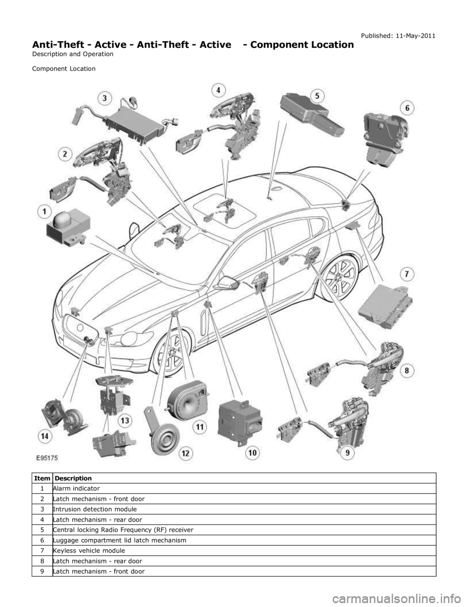
Component Location Published: 11-May-2011
Item Description 1 Alarm indicator 2 Latch mechanism - front door 3 Intrusion detection module 4 Latch mechanism - rear door 5 Central locking Radio Frequency (RF) receiver 6 Luggage compartment lid latch mechanism 7 Keyless vehicle module 8 Latch mechanism - rear door 9 Latch mechanism - front door
Page 2121 of 3039

Anti-Theft - Active - Anti-Theft - Active - Overview
Description and Operation
Overview Published: 11-May-2011
The active anti-theft system is available with three different levels of vehicle protection depending on market specification:
Hinged panel sensing
Hinged panel and intrusion sensing
Hinged panel, intrusion and inclination sensing.
The CJB (central junction box) automatically arms and disarms the active anti-theft system when it functions the central
locking system.
Refer to: Handles, Locks, Latches and Entry Systems (501-14 Handles, Locks, Latches and Entry Systems, Description and Operation).
Depending on market specification two modes of protection are used: perimeter mode and volumetric mode.
Perimeter mode
Perimeter mode, monitors the security of the hinged panels, which include:
all doors,
luggage compartment lid, and
engine compartment lid.
When perimeter mode is active, the CJB monitors the panel ajar switches in the latch mechanisms of the hinged panels.
Volumetric mode
In volumetric mode the CJB monitors the interior of the vehicle for movement using an ultrasonic sound wave sensor.
If the battery backed sounder incorporates an inclination sensor the vehicle will also be monitored for unauthorised tilting; for
example towing or jacking.
Page 2123 of 3039

7 Central locking - Radio Frequency (RF) receiver 8 Engine compartment lid - latch mechanism 9 Passive sounder 10 Battery backed sounder 11 Alarm indicator 12 Instrument cluster 13 Start control unit 14 Luggage compartment lid - latch mechanism 15 Door latch mechanism - LH (left-hand) rear 16 Door latch mechanism - RH (right-hand) rear 17 Door latch mechanism - RH front 18 Door latch mechanism - LH front 19 Door module - LH rear 20 Door module - RH rear 21 Door module - RH front 22 Door module - LH front 23 Intrusion detection module
Anti-Theft - Active System Operation
The active anti-theft system is available with three different levels of vehicle protection depending on market specification:
Hinged panel sensing
Hinged panel and intrusion sensing
Hinged panel, intrusion and inclination sensing.
The system is controlled by software in the CJB and RJB and indicates a trigger condition: Visually, using the direction indicators, and
Audibly, using the vehicle horn and either a passive or active sounder to indicate a trigger condition.
The passive sounder takes the form of an anti-theft disc horn located at the rear of the engine compartment on the LH side. The active sounder takes the form of a battery backed sounder located in the same position.
Depending on market specification, the battery backed sounder may be fitted with an inclination sensor. Both types of battery
backed sounder are visually identical and can only be identified by their part number. Both are also intelligent units, and
communicate to the CJB over a LIN (local interconnect network) bus connection.
Monitoring of the hinged panels is carried out using switches located in each door latch assembly, the engine-compartment-lid
latch assembly, and the luggage-compartment-lid latch assembly. The condition of the switches is monitored by the CJB.
Monitoring of front door lock status is carried out using switches located in the door latch mechanisms. The condition of the
switches is monitored by the front door modules and transmitted to the CJB over the medium speed CAN (controller area
network) bus.
Monitoring of the cabin interior is carried out using an intrusion detection module mounted behind the roof console. The
intrusion detection module comprises an ultrasonic sound wave sensor to determine if there is movement within the cabin.
Information from the intrusion detection module is communicated to the CJB over a LIN bus connection.
CAUTIONS:
The intrusion detection module electrical connections, particularly those to the sensors mounted in the roof console, are
very delicate and must be handled with care.
The intrusion detection module is an electro-statically sensitive part and should only be handled in an electro-statically
controlled environment.
When armed, the active anti-theft system can be triggered in one of the following ways:
A door ajar switch indicates a door has been opened.
The engine compartment lid or luggage compartment lid ajar switches indicate that either has been opened.
Either front door latch mechanism indicates a door has been unlocked.
The emergency key blade is used to open either the LH front door or luggage compartment.
The CJB or RJB are disconnected (this may result in only a partial trigger).
An attempt is made to start the engine without a valid signal from the Smart Key.
Refer to: Anti-Theft - Passive (419-01B Anti-Theft - Passive, Description and Operation).