2010 JAGUAR XFR steering
[x] Cancel search: steeringPage 1944 of 3039

12 Portable audio interface console (Optional) 13 Portable audio module (Optional) 14 Steering wheel remote audio controls
Page 1947 of 3039
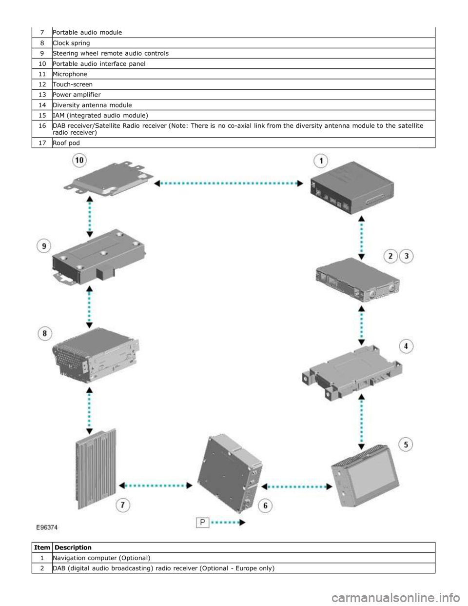
8 Clock spring 9 Steering wheel remote audio controls 10 Portable audio interface panel 11 Microphone 12 Touch-screen 13 Power amplifier 14 Diversity antenna module 15 IAM (integrated audio module) 16 DAB receiver/Satellite Radio receiver (Note: There is no co-axial link from the diversity antenna module to the satellite radio receiver) 17 Roof pod
Item Description 1 Navigation computer (Optional) 2 DAB (digital audio broadcasting) radio receiver (Optional - Europe only)
Page 1949 of 3039
systems.
A typical example of information transfer is vehicle speed information from the ABS (anti-lock brake system) module used to
control the automatic volume control function. The vehicle speed information from the ABS module is sent on the high speed
CAN network and collected by the instrument panel gateway. The signal is passed to the medium speed CAN network and onto the ICM gateway. The ICM calculates the volume adjustment required. The corrected audio volume level signal is sent on the
MOST network to the IAM or Power amplifier (dependant on vehicle equipment level) for output to the speaker system.
AUDIO SYSTEM USER CONTROLS
Touch-Screen
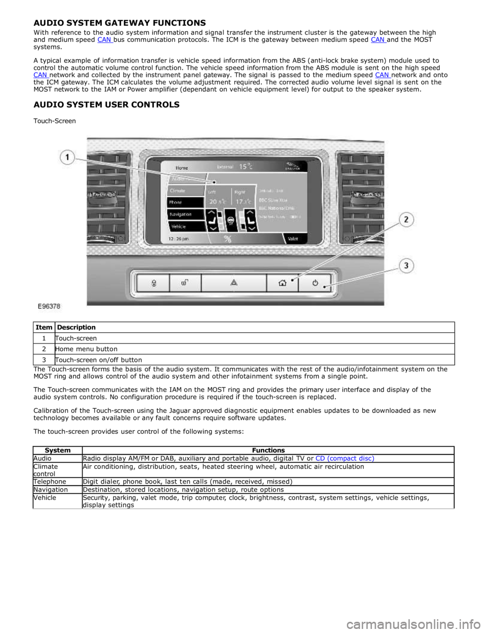
Item Description 1 Touch-screen 2 Home menu button 3 Touch-screen on/off button The Touch-screen forms the basis of the audio system. It communicates with the rest of the audio/infotainment system on the
MOST ring and allows control of the audio system and other infotainment systems from a single point.
The Touch-screen communicates with the IAM on the MOST ring and provides the primary user interface and display of the
audio system controls. No configuration procedure is required if the touch-screen is replaced.
Calibration of the Touch-screen using the Jaguar approved diagnostic equipment enables updates to be downloaded as new
technology becomes available or any fault concerns require software updates.
The touch-screen provides user control of the following systems:
System Functions Audio Radio display AM/FM or DAB, auxiliary and portable audio, digital TV or CD (compact disc) Climate
control Air conditioning, distribution, seats, heated steering wheel, automatic air recirculation Telephone Digit dialer, phone book, last ten calls (made, received, missed) Navigation Destination, stored locations, navigation setup, route options Vehicle
Security, parking, valet mode, trip computer, clock, brightness, contrast, system settings, vehicle settings, display settings
Page 1951 of 3039
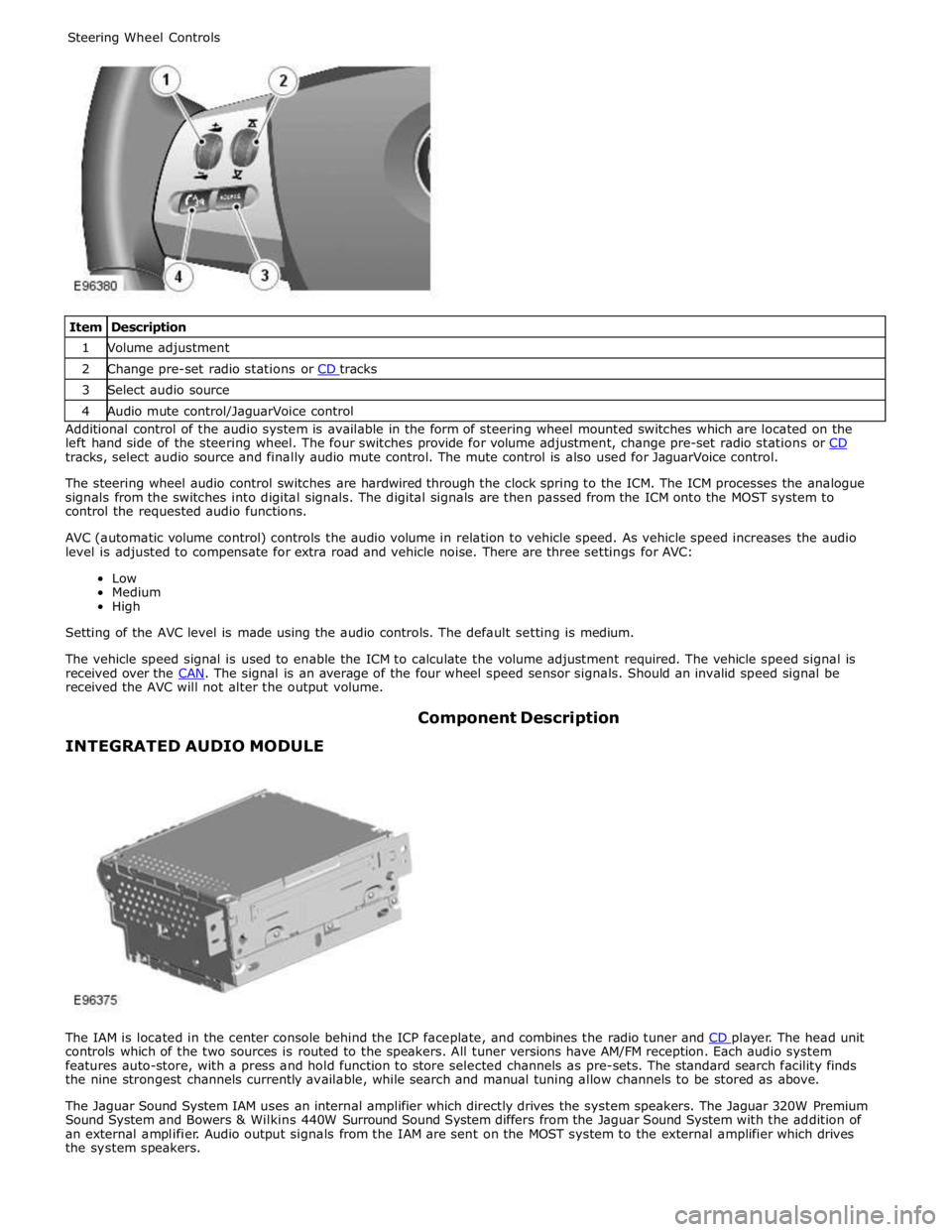
1 Volume adjustment 2 Change pre-set radio stations or CD tracks 3 Select audio source 4 Audio mute control/JaguarVoice control Additional control of the audio system is available in the form of steering wheel mounted switches which are located on the
left hand side of the steering wheel. The four switches provide for volume adjustment, change pre-set radio stations or CD tracks, select audio source and finally audio mute control. The mute control is also used for JaguarVoice control.
The steering wheel audio control switches are hardwired through the clock spring to the ICM. The ICM processes the analogue
signals from the switches into digital signals. The digital signals are then passed from the ICM onto the MOST system to
control the requested audio functions.
AVC (automatic volume control) controls the audio volume in relation to vehicle speed. As vehicle speed increases the audio
level is adjusted to compensate for extra road and vehicle noise. There are three settings for AVC:
Low
Medium
High
Setting of the AVC level is made using the audio controls. The default setting is medium.
The vehicle speed signal is used to enable the ICM to calculate the volume adjustment required. The vehicle speed signal is
received over the CAN. The signal is an average of the four wheel speed sensor signals. Should an invalid speed signal be received the AVC will not alter the output volume.
INTEGRATED AUDIO MODULE Component Description
The IAM is located in the center console behind the ICP faceplate, and combines the radio tuner and CD player. The head unit controls which of the two sources is routed to the speakers. All tuner versions have AM/FM reception. Each audio system
features auto-store, with a press and hold function to store selected channels as pre-sets. The standard search facility finds
the nine strongest channels currently available, while search and manual tuning allow channels to be stored as above.
The Jaguar Sound System IAM uses an internal amplifier which directly drives the system speakers. The Jaguar 320W Premium
Sound System and Bowers & Wilkins 440W Surround Sound System differs from the Jaguar Sound System with the addition of
an external amplifier. Audio output signals from the IAM are sent on the MOST system to the external amplifier which drives
the system speakers.
Page 1969 of 3039
1
2
3
1
2
3
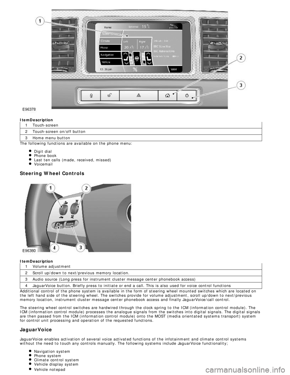
4ItemDescription
Touch-s creen
Touch-s creen on/off but ton
Home menu butt on
The fol lowing funct ions are avai lable on the phone menu:
Digi t dialPhone bookLast t en calls (made, received, mis s ed)VoicemailSteering Wheel ControlsItemDescription
Vol ume adjus tment
Scrol l up/down t o next /previ ous memory locat ion.
Audio s ource (Long pres s for ins trument cl us t er mess age cent er phonebook acces s)
JaguarVoice butt on. Briefly press to i nit iat e or end a call. This is al so used for voi ce cont rol functi ons
Addit ional control of t he phone s ys t em i s avai lable in t he form of s t eering wheel mo unted swi tches which are located on
t he left hand s i de of the s t eering wheel. The s wi tches provide for vol ume adjus tment , s croll up/down t o next/previous
memory locati on, i nst rument clus ter mes s age cent er phonebook access and final ly JaguarVoi ce/cal l cont rol.
The s teeri ng wheel control swit ches are hardwired t hrough the cl ock s pri ng t o the ICM (i nformat ion cont rol module). The
ICM (informati on cont rol module) proces ses t he analogue s ignals from the swi tches int o digi tal s ignals . The digit al si gnal s
are then pas sed from t he ICM (informati on cont rol module) onto the MOST (medi a ori ent ated sys tems transport ) s yst em
for control uni t proces s ing and operat ion of t he reques ted funct ions .
JaguarVoice
JaguarVoi ce enables acti vat ion of s everal voi ce act ivat ed functi ons of t he infotainment and cli mate cont rol s ys t ems
wit hout the need t o t ouch any controls manuall y. The foll owi ng s yst ems i ncl ude JaguarVoice funct ional it y;
Navigati on s ys t emPhone sys temCli mate cont rol s ys t emVehicle di spl ay sys t emVehicle not epad
Page 1973 of 3039

Published: 11-May-2011
Information and Entertainment System - Navigation System - Overview
Description and Operation
OVERVIEW
The navigation system provides audible and visual route guidance information to enable the driver to reach a desired
destination. The system allows the driver to choose the desired route using minor or major roads and will present 3 routes to
the driver based on user preferences. Directions to hospitals, museums, monuments and hotels are also available. The
navigation computer uses map information stored on a DVD (digital versatile disc) to determine the best route for the journey
and provide the driver with details of directions and approaching junctions.
The navigation system has various levels of user control through the Touch-screen and JaguarVoice system. System volume
adjustment can be made using the ICP (integrated control panel), Touch-screen and steering wheel controls.
There are 3 navigation system variants specific to various markets. On all systems the GPS (global positioning system) signal
is received by the GPS (global positioning system) antenna located in the roof pod antenna module.
The European navigation system includes the TMC (traffic messaging channel) function, which receives traffic information from
an FM antenna integrated into the heated rear window. On a pre-selected route the system will offer re-routing options
depending on traffic conditions.
The Japanese navigation system includes the VICS (vehicle information and communication systems) function. The VICS
(vehicle information and communication systems) supplies information to enable the navigation computer to re-route the
navigation guidance or to inform the vehicle driver of traffic conditions in the vehicles vicinity. Information is provided to the
system through an FM antenna integrated into the heated rear window and a VICS beacon located in the LH upper side of the
instrument panel.
The NAS (North American specification) variant does not include any additional traffic information systems.
The navigation system is primarily controlled from the Touch-screen which is located in the center of the instrument panel.
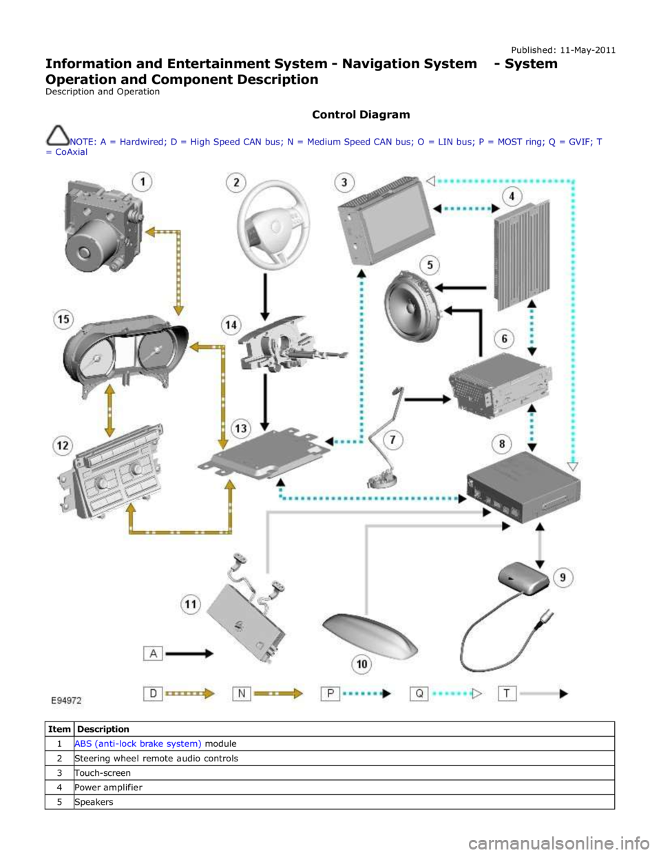
Control signals from the Touch-screen are sent on the MOST (media oriented systems transport) ring to the navigation
computer. The navigation computer uses a dedicated GVIF (gigabit video interface) bus to transmit video signals to the Touch-
screen.
Depending upon the audio system version fitted the navigation audio output signals are sent on the MOST (media oriented
systems transport) ring to the IAM (integrated audio module) or the power amplifier for speaker output.
Page 1974 of 3039
Published: 11-May-2011
Information and Entertainment System - Navigation System - System
Operation and Component Description
Description and Operation
Control Diagram
NOTE: A = Hardwired; D = High Speed CAN bus; N = Medium Speed CAN bus; O = LIN bus; P = MOST ring; Q = GVIF; T
= CoAxial
Item Description 1 ABS (anti-lock brake system) module 2 Steering wheel remote audio controls 3 Touch-screen 4 Power amplifier 5 Speakers
Page 1980 of 3039
the roof pod and is shared with the DAB (digital audio broadcasting) band L antenna or satellite radio antenna where fitted.
The roof pod is located externally in a central position towards the rear of the roof.
The GPS antenna is designed with 50 ohm output impedance. The navigation computer is fitted with 50 ohm fakra II connectors to ensure compatibility with the antenna. For optimum performance 50 ohm low loss coaxial cable is used between
the antenna and navigation computer.
It is possible for the GPS antenna to lose the signal from the GPS satellites; In hilly or tree lined areas
Built up areas with tall buildings
In multi storey car parks
In garages
In tunnels
On bridges
During heavy rain or thunderstorms
When the signal is lost the navigation computer will continue to give guidance using memory mapped data from the DVD map until the signal is restored.
TMC/VICS FM Antenna
Data messages for both TMC (traffic message channel) and VICS (vehicle information and communication system) are received
through the FM antennas and diversity antenna module located in the heated rear window.
VICS Beacon Antenna (Japan Only)
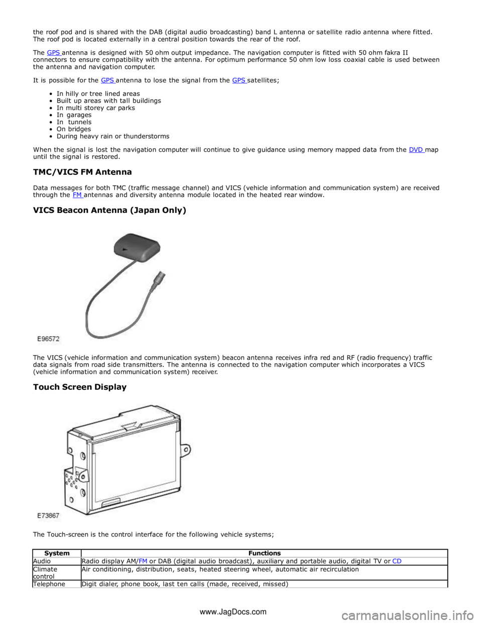
The VICS (vehicle information and communication system) beacon antenna receives infra red and RF (radio frequency) traffic
data signals from road side transmitters. The antenna is connected to the navigation computer which incorporates a VICS
(vehicle information and communication system) receiver.
Touch Screen Display
The Touch-screen is the control interface for the following vehicle systems;
System Functions Audio Radio display AM/FM or DAB (digital audio broadcast), auxiliary and portable audio, digital TV or CD Climate
control Air conditioning, distribution, seats, heated steering wheel, automatic air recirculation Telephone Digit dialer, phone book, last ten calls (made, received, missed) www.JagDocs.com