Page 1981 of 3039

Navigation Destination, stored locations, navigation setup, route options Vehicle
Security, parking, valet mode, trip computer, clock, brightness, contrast, system settings, vehicle settings, display settings The screen is a touch sensitive 7 inch LCD (liquid crystal display) VGA screen containing 800 x 480 pixels in a 15:9 format. The
screen processes its own video for system operation but receives the navigation graphics from the navigation computer.
Steering Wheel Controls
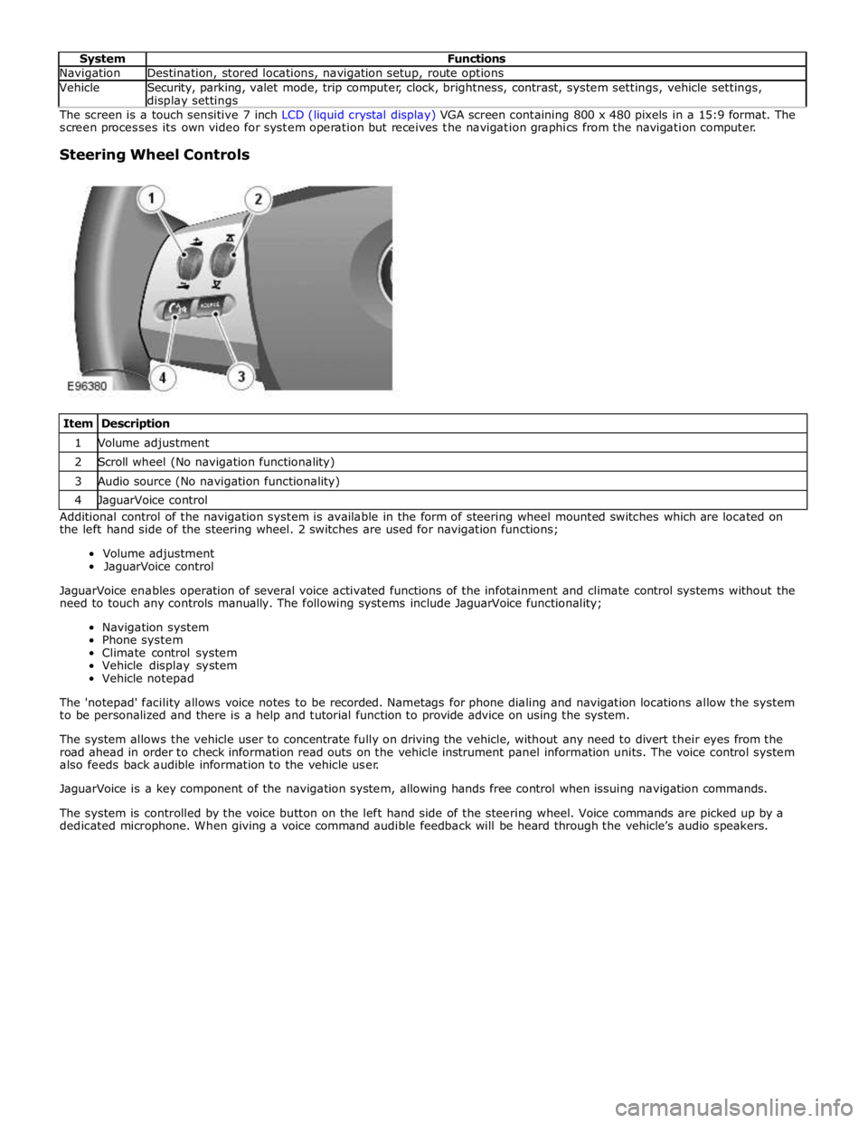
Item Description 1 Volume adjustment 2 Scroll wheel (No navigation functionality) 3 Audio source (No navigation functionality) 4 JaguarVoice control Additional control of the navigation system is available in the form of steering wheel mounted switches which are located on
the left hand side of the steering wheel. 2 switches are used for navigation functions;
Volume adjustment
JaguarVoice control
JaguarVoice enables operation of several voice activated functions of the infotainment and climate control systems without the
need to touch any controls manually. The following systems include JaguarVoice functionality;
Navigation system
Phone system
Climate control system
Vehicle display system
Vehicle notepad
The 'notepad' facility allows voice notes to be recorded. Nametags for phone dialing and navigation locations allow the system
to be personalized and there is a help and tutorial function to provide advice on using the system.
The system allows the vehicle user to concentrate fully on driving the vehicle, without any need to divert their eyes from the
road ahead in order to check information read outs on the vehicle instrument panel information units. The voice control system
also feeds back audible information to the vehicle user.
JaguarVoice is a key component of the navigation system, allowing hands free control when issuing navigation commands.
The system is controlled by the voice button on the left hand side of the steering wheel. Voice commands are picked up by a
dedicated microphone. When giving a voice command audible feedback will be heard through the vehicle’s audio speakers.
Page 1989 of 3039

1
2
3
4
5
6
1
2
3
4Touch-s creen
Seek up but ton
Set ti ngs but ton
O n/off and volume cont rol
Source but ton
Seek down but ton
The ICP (i ntegrat ed cont rol panel ) dupl icates many of t he Touch-s creen tel evi si on user control features . The ICP
(integrat ed cont rol panel) communicates wi th the televis i on sys t em t hrough the medium speed CAN and MOST (medi a
ori ent ated sys tems trans port ) bus s ys t ems .
Steering Wheel ControlsItemDescription
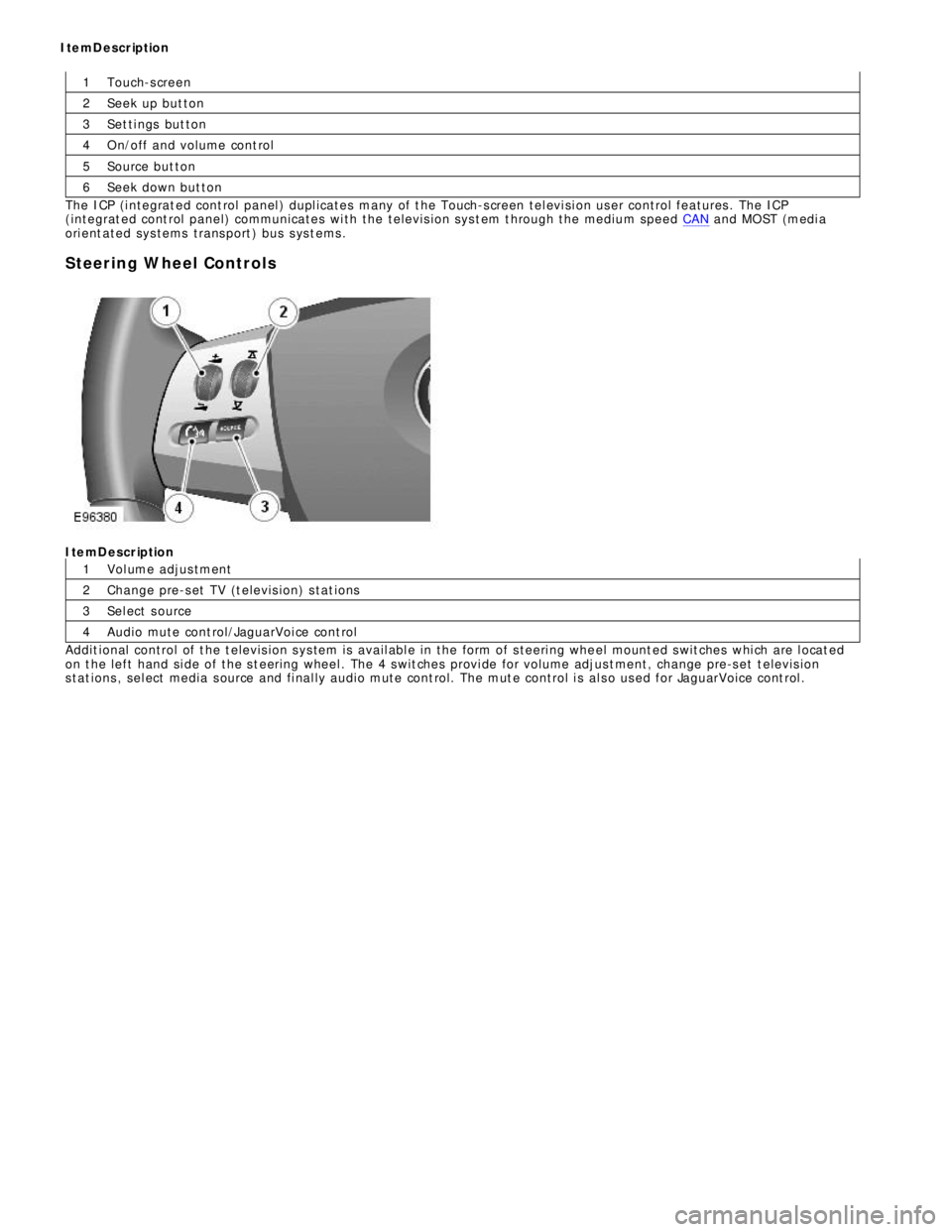
Vol ume adjus tment
Change pre-s et TV (t elevis ion) s tat ions
Sel ect s ource
Audio mute cont rol/JaguarVoi ce cont rol
Addit ional control of t he t elevis ion s ys tem is avail abl e in the form of s teeri ng whe el mount ed s wit ches whi ch are l ocat ed
on t he left hand si de of the s t eering wheel . The 4 s wit ches provi de for volume adjus t ment, change pre-s et t elevis ion
s tat ions , sel ect media s ource and fi nal ly audio mute cont rol. The mut e control i s al s o us ed for JaguarVoice cont rol . ItemDescription
Page 2001 of 3039
Published: 11-May-2011
Information and Entertainment System - Steering Wheel Audio Controls
Removal and Installation
Removal
NOTE: Removal steps in this procedure may contain installation details.
1. Make the SRS system safe.
Refer to: Standard Workshop Practices (100-00 General Information, Description and Operation).
2. Refer to: Driver Air Bag Module (501-20B Supplemental Restraint System, Removal and Installation).
3. Refer to: Upshift Paddle Switch (307-05A Automatic Transmission/Transaxle External Controls - V6 3.0L Petrol, Removal and
Installation).
4. Refer to: Downshift Paddle Switch (307-05A Automatic Transmission/Transaxle External Controls - V6 3.0L Petrol, Removal and
Installation).
5. Torque: 3 Nm 6. Torque: 3 Nm
Page 2020 of 3039
1 Front height sensor 2 Headlamp leveling module 3 Rain/light sensor 4 Rear height sensor 5 Light switch - LH (left-hand) steering column multifunction switch 6 Auxiliary lighting switch 7 Side marker lamp (NAS only) (2 off) 8 Front turn signal indicator (2 off) 9 Halogen or xenon headlamp projector module (2 off) 10 Cornering/Static bending lamp (where fitted) (2 off) www.JagDocs.com
Page 2024 of 3039
8 Rear height sensor 9 RH (right-hand) headlamp assembly 10 LH (left-hand) headlamp assembly 11 Lighting control switch - LH steering column multifunction switch 12 Instrument cluster HALOGEN HEADLAMPS - CONTROL DIAGRAM
Item Description A = Hardwired; N = Medium speed CAN bus 1 Battery 2 BJB 3 CJB 4 EJB 5 Auxiliary lighting switch
Page 2025 of 3039
7 LH headlamp assembly 8 Lighting control switch - LH steering column multifunction switch 9 Instrument cluster SIDE LAMPS/TURN SIGNAL INDICATORS/FOG LAMPS - CONTROL DIAGRAM
Item Description A = Hardwired; N = Medium speed CAN bus; O = LIN bus 1 Battery 2 BJB - Megafuse 3 Stop lamp switch 4 LH turn signal indicator 5 RJB (rear junction box) 6 RH turn signal indicator 7 RH licence plate lamp www.JagDocs.com
Page 2026 of 3039

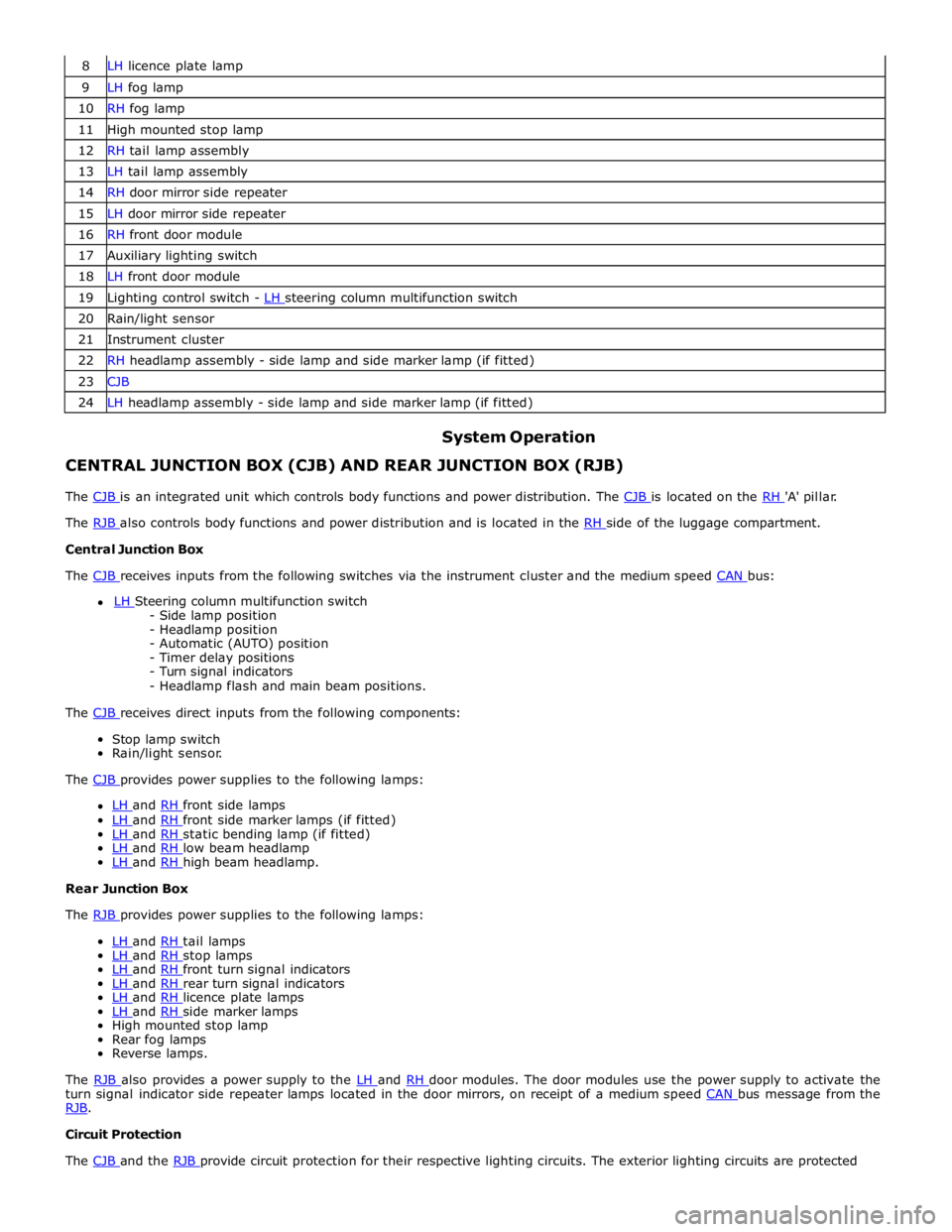
8 LH licence plate lamp 9 LH fog lamp 10 RH fog lamp 11 High mounted stop lamp 12 RH tail lamp assembly 13 LH tail lamp assembly 14 RH door mirror side repeater 15 LH door mirror side repeater 16 RH front door module 17 Auxiliary lighting switch 18 LH front door module 19 Lighting control switch - LH steering column multifunction switch 20 Rain/light sensor 21 Instrument cluster 22 RH headlamp assembly - side lamp and side marker lamp (if fitted) 23 CJB 24 LH headlamp assembly - side lamp and side marker lamp (if fitted)
System Operation CENTRAL JUNCTION BOX (CJB) AND REAR JUNCTION BOX (RJB)
The CJB is an integrated unit which controls body functions and power distribution. The CJB is located on the RH 'A' pillar. The RJB also controls body functions and power distribution and is located in the RH side of the luggage compartment. Central Junction Box
The CJB receives inputs from the following switches via the instrument cluster and the medium speed CAN bus: LH Steering column multifunction switch - Side lamp position
- Headlamp position
- Automatic (AUTO) position
- Timer delay positions
- Turn signal indicators
- Headlamp flash and main beam positions.
The CJB receives direct inputs from the following components: Stop lamp switch
Rain/light sensor.
The CJB provides power supplies to the following lamps:
LH and RH front side lamps LH and RH front side marker lamps (if fitted) LH and RH static bending lamp (if fitted) LH and RH low beam headlamp LH and RH high beam headlamp. Rear Junction Box
The RJB provides power supplies to the following lamps:
LH and RH tail lamps LH and RH stop lamps LH and RH front turn signal indicators LH and RH rear turn signal indicators LH and RH licence plate lamps LH and RH side marker lamps High mounted stop lamp
Rear fog lamps
Reverse lamps.
The RJB also provides a power supply to the LH and RH door modules. The door modules use the power supply to activate the turn signal indicator side repeater lamps located in the door mirrors, on receipt of a medium speed CAN bus message from the RJB. Circuit Protection
The CJB and the RJB provide circuit protection for their respective lighting circuits. The exterior lighting circuits are protected
Page 2029 of 3039

Bulb Type Rating Reverse lamps - All markets PS19W 19W Licence plate lamps - All markets W5W 5W LIGHTING CONTROL SWITCH
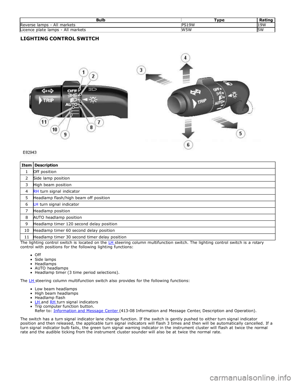
Item Description 1 Off position 2 Side lamp position 3 High beam position 4 RH turn signal indicator 5 Headlamp flash/high beam off position 6 LH turn signal indicator 7 Headlamp position 8 AUTO headlamp position 9 Headlamp timer 120 second delay position 10 Headlamp timer 60 second delay position 11 Headlamp timer 30 second timer delay position The lighting control switch is located on the LH steering column multifunction switch. The lighting control switch is a rotary control with positions for the following lighting functions:
Off
Side lamps
Headlamps
AUTO headlamps
Headlamp timer (3 time period selections).
The LH steering column multifunction switch also provides for the following functions: Low beam headlamps
High beam headlamps
Headlamp flash
LH and RH turn signal indicators Trip computer function button.
Refer to: Information and Message Center (413-08 Information and Message Center, Description and Operation).
The switch has a turn signal indicator lane change function. If the switch is gently pushed to either turn signal indicator
position and then released, the applicable turn signal indicators will flash 3 times and then will be automatically cancelled. If a
turn signal indicator bulb fails, the green turn signal warning indicator in the instrument cluster will flash at twice the normal
rate and the audible ticking from the instrument cluster sounder will also be at twice the normal rate.