Page 2616 of 3039

and the safety belt buckle sensor. Based on this data, the RCM decides which level of airbag module deployment is required and forwards the information to the second area, the deployment handler.
The deployment handler evaluates the status of the seat track position sensor and safety belt buckle sensors before a decision
is made about which restraints should finally be deployed.
Data from the side crash sensors is used by the RCM in conjunction with acceleration data from the RCM internal accelerometer to make a deployment decision. The RCM processes the acceleration data and subject to an impact being of high enough severity, decides whether the side airbag module should be deployed.
On board testing of the airbag modules, front safety belt pretensioner firing circuits, warning indicator circuits and module
status (the crash and side impact sensors perform basic self-tests) is performed by the RCM together with the storing of fault codes.
The RCM drives the SRS indicator on the instrument pack via a CAN signal. If the warning lamp fails, a fault code is recorded and a warning tone is sounded in place of the lamp if a further fault occurs. It also provides a temporary back-up power supply
to operate the airbag modules in the event that in crash conditions, the battery supply is lost. In the event of a crash, it
records certain data which can be accessed via the diagnostic connector.
A safing sensor in the RCM provides confirmation of an impact to verify if airbag and pretensioner activation is necessary. A roll-over sensor monitors the lateral attitude of the vehicle. Various firing strategies are employed by the RCM to ensure that during an accident only the appropriate airbags and pretensioners are fired. The firing strategy used also depends on the
inputs from the safety belt switches and the occupant monitoring system.
An energy reserve in the RCM ensures there is always a minimum of 150 milliseconds of stored energy available if the power supply from the ignition switch is disrupted during a crash. The stored energy is sufficient to produce firing signals for the
driver airbag, the passenger airbag and the safety belt pretensioners.
When the ignition is switched on, the RCM performs a self-test and then performs cyclical monitoring of the system. If a fault is detected the RCM stores a related fault code and illuminates the airbag warning indicator. The faults can be retrieved by the recommended Jaguar diagnostic tool over the CAN bus. If a fault that could cause a false fire signal is detected, the RCM disables the respective firing circuit, and keeps it disabled during a crash event.
Clock Spring
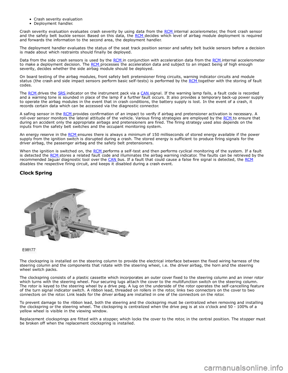
The clockspring is installed on the steering column to provide the electrical interface between the fixed wiring harness of the
steering column and the components that rotate with the steering wheel, i.e. the driver airbag, the horn and the steering
wheel switch packs.
The clockspring consists of a plastic cassette which incorporates an outer cover fixed to the steering column and an inner rotor
which turns with the steering wheel. Four securing lugs attach the cover to the multifunction switch on the steering column.
The rotor is keyed to the steering wheel by a drive peg. A lug on the underside of the rotor operates the self-cancelling feature
of the turn signal indicator switch. A ribbon lead, threaded on rollers in the rotor, links two connectors on the cover to two
connectors on the rotor. Link leads for the driver airbag are installed in one of the connectors on the rotor.
To prevent damage to the ribbon lead, both the steering and the clockspring must be centralized when removing and installing
the clockspring or the steering wheel. The clockspring is centralized when the drive peg is at six o'clock and 50 - 100% of a
yellow wheel is visible in the viewing window.
Replacement clocksprings are fitted with a stopper, which locks the cover to the rotor, in the central position. The stopper must
be broken off when the replacement clockspring is installed.
Page 2617 of 3039

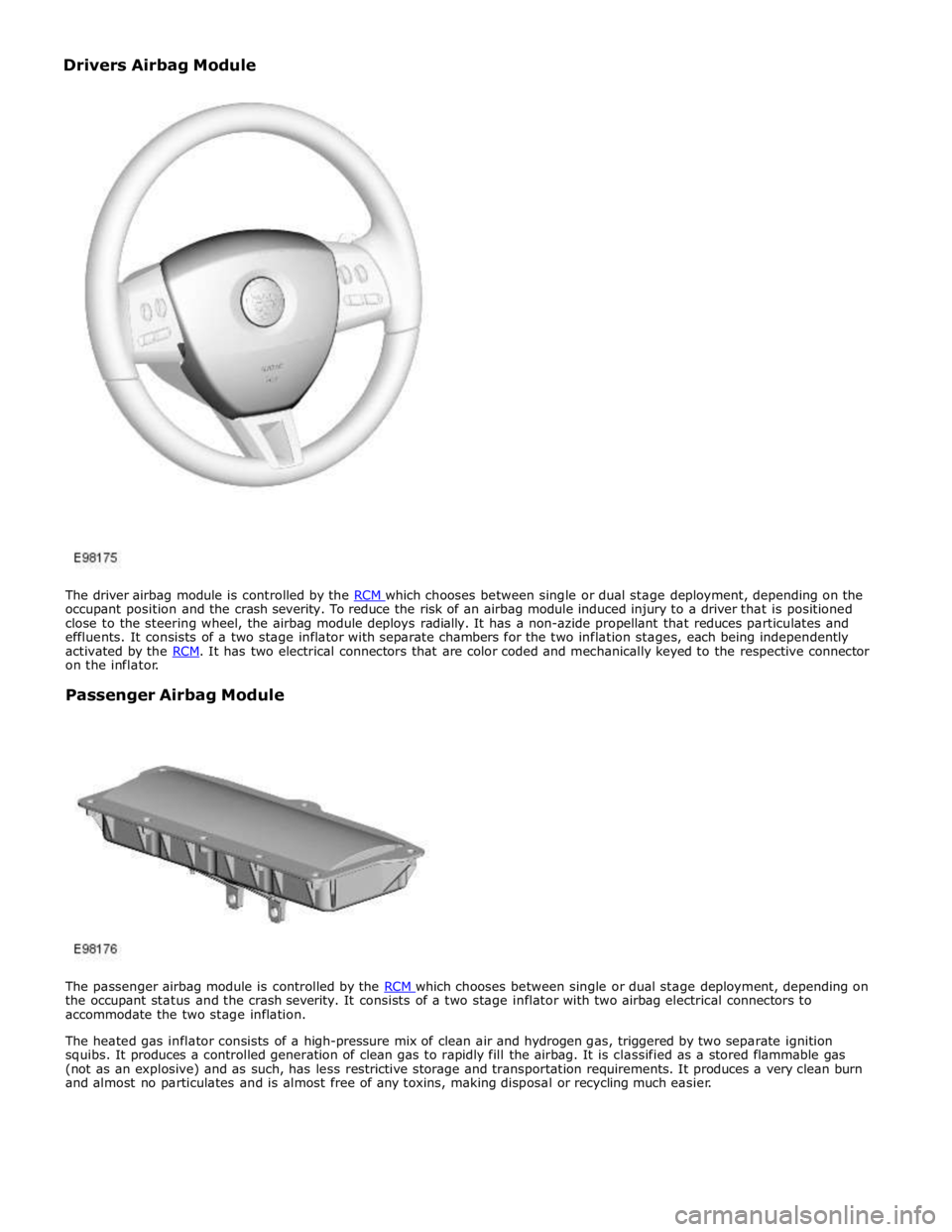
occupant position and the crash severity. To reduce the risk of an airbag module induced injury to a driver that is positioned
close to the steering wheel, the airbag module deploys radially. It has a non-azide propellant that reduces particulates and
effluents. It consists of a two stage inflator with separate chambers for the two inflation stages, each being independently
activated by the RCM. It has two electrical connectors that are color coded and mechanically keyed to the respective connector on the inflator.
Passenger Airbag Module
The passenger airbag module is controlled by the RCM which chooses between single or dual stage deployment, depending on the occupant status and the crash severity. It consists of a two stage inflator with two airbag electrical connectors to
accommodate the two stage inflation.
The heated gas inflator consists of a high-pressure mix of clean air and hydrogen gas, triggered by two separate ignition
squibs. It produces a controlled generation of clean gas to rapidly fill the airbag. It is classified as a stored flammable gas
(not as an explosive) and as such, has less restrictive storage and transportation requirements. It produces a very clean burn
and almost no particulates and is almost free of any toxins, making disposal or recycling much easier. Drivers Airbag Module
Page 2630 of 3039
Make sure that the road wheels are in the straight ahead position,
failure to follow this instruction may result in damage to the vehicle.
Refer to: Steering Wheel (211-04 Steering Column, Removal and Installation).
3. CAUTION: Failing to install the special tool to the
clockspring may result in damage to the vehicle.
Special Tool(s): 211-326
4.
Page 2633 of 3039
Installation
1. CAUTIONS:
Make sure that special tool 211-326 is installed to the
clockspring.
Make sure that the arrow on the cassette is centered
and pointing vertically (make sure that the steering wheel
has remained in the 12 o'clock position and that it has
not been turned by +/- 360 degrees) prior to the
steering wheel installation. On removal of the special tool,
keep the clockspring cables taught to prevent the cassette
moving from the set position. Failure to follow this
instruction may result in damage to the component.
Make sure that the road wheels are in the straight
ahead position, failure to follow this instruction may result
in damage to the vehicle.
To install, reverse the removal procedure.
Page 2653 of 3039
Supplemental Restraint System - Passenger Air Bag Module
Removal and Installation Published: 11-May-2011
Removal
NOTE: Removal steps in this procedure may contain installation details.
1. Refer to: Battery Disconnect and Connect (414-01 Battery, Mounting and Cables, General Procedures).
2. Refer to: Steering Wheel (211-04 Steering Column, Removal and Installation).
3. Refer to: Driver Side Register (412-01 Climate Control, Removal and Installation).
4. Refer to: Information and Entertainment Display (415-01A Information and Entertainment System, Removal and Installation).
5. Refer to: Instrument Panel Speaker (415-01A Information and Entertainment System, Removal and Installation).
6. Refer to: A-Pillar Trim Panel (501-05 Interior Trim and Ornamentation, Removal and Installation).
7. Refer to: Audio and Climate Control Assembly (415-01A Information and Entertainment System, Removal and Installation). 211-326
Locking Tool, Clockspring Special Tool(s)
Page 3013 of 3039
Front lower arm to front subframe retaining nut and bolt 175 129 - Rear lower arm to front subframe retaining nut and bolt 175 129 - Engine mount lower retaining nut 63 46 - Steering gear retaining bolts 100 74 - Front Shock absorber and spring assembly retaining bolt 175 129 - Front subframe to body front retaining bolt Stage 1 100 73 - Stage 2 270° 270° - Front subframe to body rear retaining bolt Stage 1 80 59 - Stage 2 240° 240° - Front Stabilizer bar link retaining nuts 43 31 - Front Stabilizer bar link retaining bolts 55 41 - Rear Shock absorber and spring assembly retaining bolt 133 98 - Rear subframe reinforcement plate retaining bolts 47 35 - Rear subframe to body retaining bolts Stage 1 80 59 - Stage 2 240° 240° -
Page 3018 of 3039
14.
15.
CAUTION:
Make sure to support the steering gear.
NOTE:
LHD illustration shown, RHD is similar.
16.