2010 JAGUAR XFR steering
[x] Cancel search: steeringPage 1646 of 3039

Published: 08-Nov-2013
Speed Control - V8 5.0L Petrol/V8 S/C 5.0L Petrol - Speed Control
Diagnosis and Testing
Principles of Operation
For a detailed description of the speed control system, refer to the relevant Description and Operation sections in the
workshop manual.
Inspection and Verification
CAUTION: Diagnosis by substitution from a donor vehicle is NOT acceptable. Substitution of control modules does not
guarantee confirmation of a fault, and may also cause additional faults in the vehicle being tested and/or the donor vehicle.
1. Verify the customer concern.
2. Visually inspect for obvious signs of damage and system integrity.
Visual Inspection
Mechanical Electrical
Speed control sensor
Ensure the speed control sensor is free from obstructions
Speed control module
Brake switch
Fuses
Wiring harness
Electrical connector(s)
Steering wheel switches
Brake switch
Speed control sensor
Speed control module
Engine Control Module (ECM)
3. If an obvious cause for an observed or reported concern is found, correct the cause (if possible) before proceeding to
the next step.
4. If the cause is not visually evident, verify the symptom and refer to the Symptom Chart, alternatively, check for
Diagnostic Trouble Codes (DTCs) and refer to the DTC Index.
Speed Control Sensor Adjustment (vehicles with adaptive system installed)
An incorrectly aligned speed control sensor can cause incorrect system operation. Before starting any repair work on the speed
control system, on vehicles with the adaptive system installed, check speed control sensor for correct vertical alignment, and
carry out speed control sensor alignment procedure using manufacturer approved diagnostic system.
Symptom Chart
Symptom Possible Causes Action Speed control inhibited or
disabled
Power or ground supply to
speed control module or speed
control sensor
Steering wheel speed control
switch/circuits
Throttle sensors
Brake switch
Anti-Lock Brake System fault
Check for DTCs that could be caused by power or
ground failure to the module or sensor and refer to
DTC Index
Check for sticking, jammed and broken speed control
switches. Refer to the electrical circuit diagrams and
check speed control switch circuits for short, open
circuit
For throttle position sensor tests. REFER to:
Electronic Engine Controls - 3.0L Diesel (303-14
Electronic Engine Controls - 3.0L Diesel, Diagnosis and
Testing),
Electronic Engine Controls - 3.0L (303-14B Electronic Engine Controls - V6 3.0L Petrol, Diagnosis and
Testing),
Electronic Engine Controls (303-14 Electronic Engine
Controls - V8 4.2L Petrol/V8 S/C 4.2L Petrol, Diagnosis
and Testing).
Check for correct installation and adjustment of brake
switch. Refer to the electrical circuit diagrams and
check brake switch circuits for short, open circuit
Check ABS system for related DTCs and refer to the
relevant DTC Index Unable to regulate/adjust
vehicle speed
Steering wheel switch
malfunction
Check for sticking, jammed and broken speed control
switches. Refer to the electrical circuit diagrams and
check speed control switch circuits for short, open
circuit
Page 1706 of 3039
Climate Control - Control Components - Overview
Description and Operation
Overview Published: 11-May-2011
The climate control system is controlled by the ATC (automatic temperature control) module. It controls the heating and
ventilation system and the A/C (air conditioning) system to regulate the temperature, volume and distribution of air into the
passenger compartment. The system is a fully automatic dual zone system capable of maintaining individual temperature
levels selected for the LH (left-hand) and RH (right-hand) sides of the passenger compartment, up to a maximum differential
of approximately 3 ºC (5.4 ºF). Manual overrides for the system include inlet air source, blower speed and air distribution.
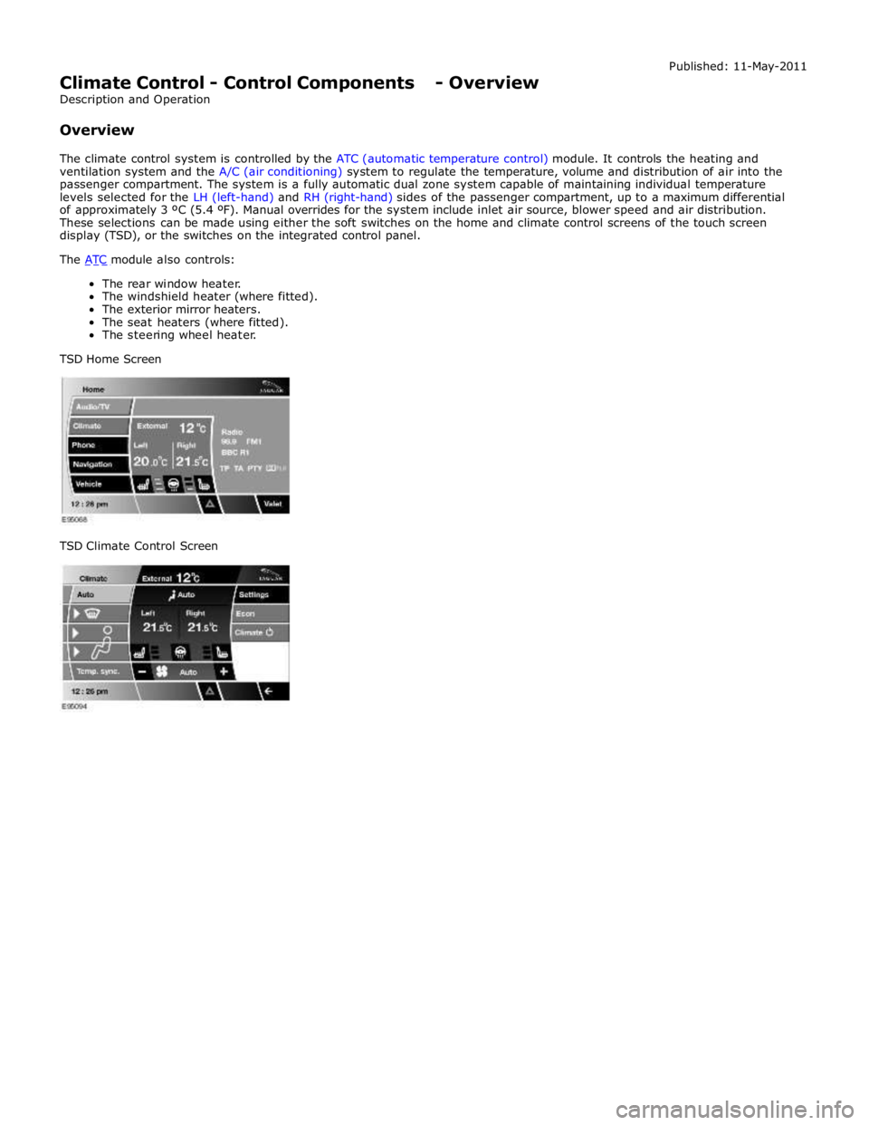
These selections can be made using either the soft switches on the home and climate control screens of the touch screen
display (TSD), or the switches on the integrated control panel.
The ATC module also controls: The rear window heater.
The windshield heater (where fitted).
The exterior mirror heaters.
The seat heaters (where fitted).
The steering wheel heater.
TSD Home Screen
TSD Climate Control Screen
Page 1712 of 3039
bus. Temperature control for the heater element is provided by the steering wheel heater control module which receives a
temperature feedback signal from a NTC (negative temperature coefficient) thermistor located within the steering wheel.
ATC Module Component Description
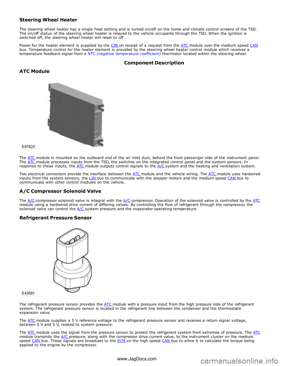
The ATC module is mounted on the outboard end of the air inlet duct, behind the front passenger side of the instrument panel. The ATC module processes inputs from the TSD, the switches on the integrated control panel and the system sensors. In response to these inputs, the ATC module outputs control signals to the A/C system and the heating and ventilation system.
Two electrical connectors provide the interface between the ATC module and the vehicle wiring. The ATC module uses hardwired inputs from the system sensors, the LIN bus to communicate with the stepper motors and the medium speed CAN bus to communicate with other control modules on the vehicle.
A/C Compressor Solenoid Valve
The A/C compressor solenoid valve is integral with the A/C compressor. Operation of the solenoid valve is controlled by the ATC module using a hardwired drive current of differing values. By controlling the flow of refrigerant through the compressor, the
solenoid valve can control the A/C system pressure and the evaporator operating temperature.
Refrigerant Pressure Sensor
The refrigerant pressure sensor provides the ATC module with a pressure input from the high pressure side of the refrigerant system. The refrigerant pressure sensor is located in the refrigerant line between the condenser and the thermostatic
expansion valve.
The ATC module supplies a 5 V reference voltage to the refrigerant pressure sensor and receives a return signal voltage, between 0 V and 5 V, related to system pressure.
The ATC module uses the signal from the pressure sensor to protect the refrigerant system from extremes of pressure. The ATC module transmits the A/C pressure, along with the compressor drive current value, to the instrument cluster on the medium speed CAN bus. These signals are broadcast to the ECM on the high speed CAN bus to allow it to calculate the torque being applied to the engine by the compressor. www.JagDocs.com
Page 1722 of 3039
Climate Control - Center Registers
Removal and Installation
Removal Published: 11-May-2011
CAUTION: Do not manually open the registers. Failure to follow this instruction may result in damage to the internal
components.
NOTES:
The center registers must be open before carrying out this procedure. To achieve this set the registers to 'Always Open'
using the climate settings tab on the information and entertainment display. If the registers are set to 'Automatic' mode
(rotating with ignition on/off) and one or more are disconnected during an ignition cycle, a vehicle battery reset may be
required to reconnect the affected registers to the LIN BUS.
Removal steps in this procedure may contain installation details.
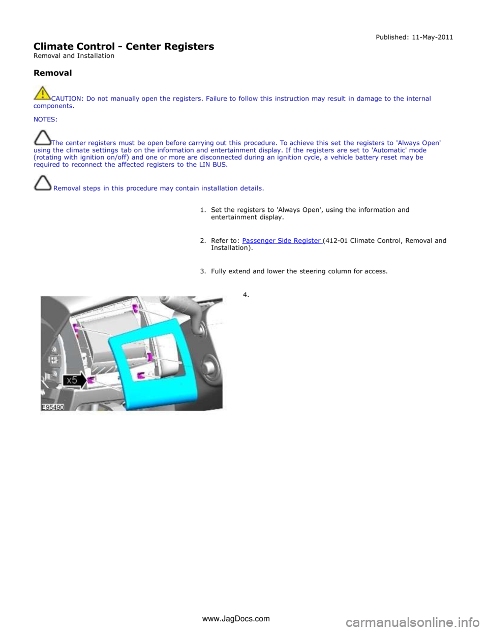
1. Set the registers to 'Always Open', using the information and
entertainment display.
2. Refer to: Passenger Side Register (412-01 Climate Control, Removal and Installation).
3. Fully extend and lower the steering column for access.
4. www.JagDocs.com
Page 1773 of 3039

A/C compressor retaining bolts 25 18 - A/C compressor manifold and tube retaining bolt 9 - 80 A/C condenser core retaining studs 5 - 48 A/C condenser core supply and return lines retaining nuts 8 - 71 Power steering oil cooler retaining nuts 7 - 62 A/C desiccant bag retaining screw (vehicles fitted with petrol engines) 22 16 - A/C desiccant bag retaining screw (vehicles fitted with diesel engines) 4 - 37 A/C pressure cutoff switch 8 - 71
Page 1784 of 3039
7 Instrument cluster 8 Steering column motor 9 High speed CAN bus connection to other vehicle systems 10 Engine oil pressure switch 11 Steering column adjustment switch 12 Brake fluid level switch 13 LH (left-hand) steering column multifunction switch 14 Start control module 15 Clockspring 16 RH (right-hand) steering column multifunction switch 17 Engine coolant level sensor 18 Auxiliary lighting switch
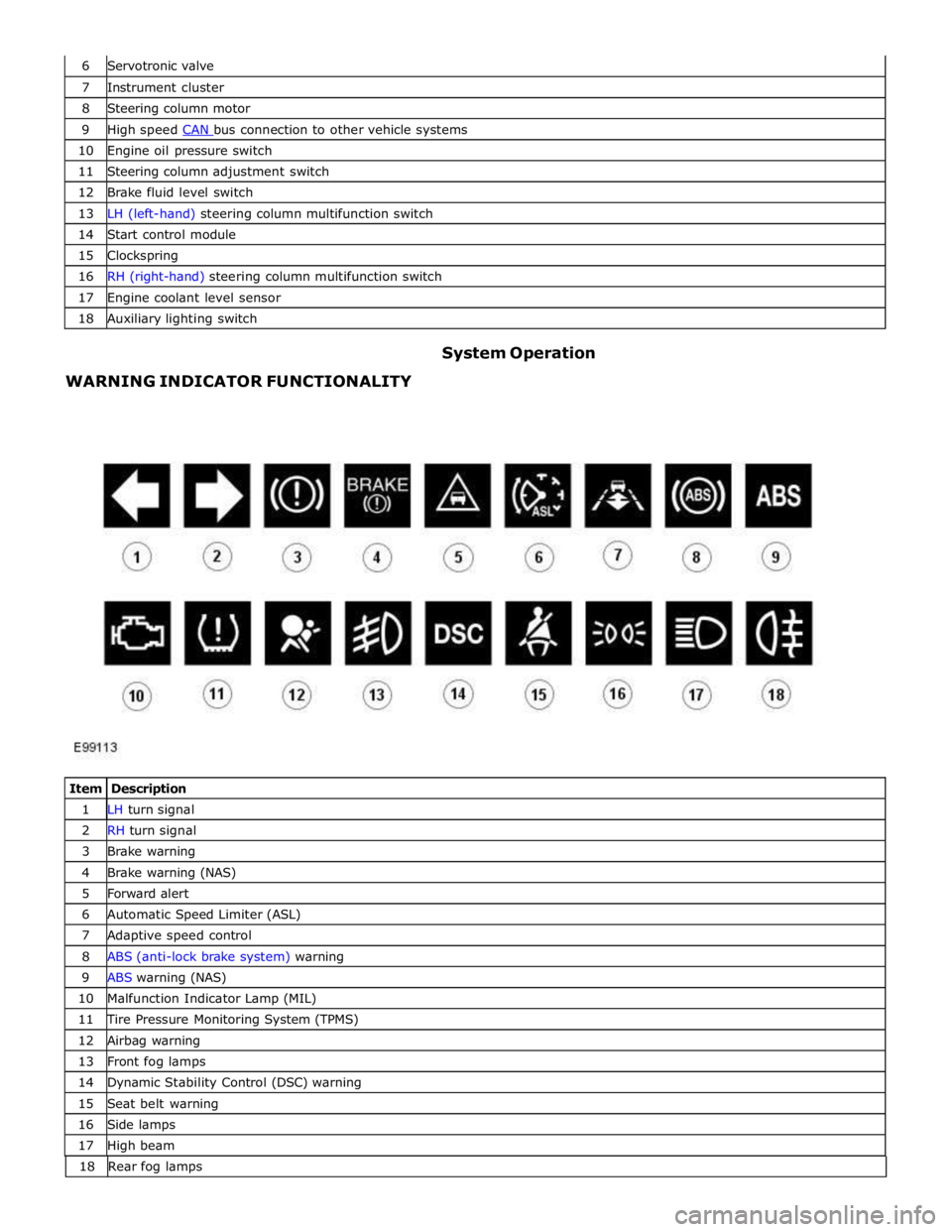
WARNING INDICATOR FUNCTIONALITY System Operation
Item Description 1 LH turn signal 2 RH turn signal 3 Brake warning 4 Brake warning (NAS) 5 Forward alert 6 Automatic Speed Limiter (ASL) 7 Adaptive speed control 8 ABS (anti-lock brake system) warning 9 ABS warning (NAS) 10 Malfunction Indicator Lamp (MIL) 11 Tire Pressure Monitoring System (TPMS) 12 Airbag warning 13 Front fog lamps 14 Dynamic Stability Control (DSC) warning 15 Seat belt warning 16 Side lamps 17 High beam 18 Rearfoglamps
Page 1785 of 3039
The functionality for each of the above warning indicators is described in the following sections:
1 and 2. Turn Signal Indicators
The turn signal indicators are controlled by the CJB on receipt of medium speed CAN bus signals from the instrument cluster.
The instrument cluster outputs a voltage to the turn signal indicator switch. The switch contains resistors of different values.
When the switch is operated in either the LH or RH direction, the voltage is passed to a ground connection in the instrument cluster which detects the reduced voltage supplied via the resistors. When the turn signal indicator switch is operated in the
LH or RH direction, the instrument cluster detects the ground voltage and determines whether a LH or RH selection is made.
The instrument cluster transmits a medium speed CAN message to the CJB for operation of the applicable turn signal indicators. The message can contain a number of states for each possible switch position and also an out of range low and
high state for circuit faults and an initial value for the switch neutral position. The turn signal indicators are not subject to the
3 second indicator check when the ignition is switched on.
The RJB (rear junction box) software controls the flash rate of the warning indicator which sends 'ON' and 'OFF' signals to the
instrument cluster which flashes the indicators in a green color. During normal operation, the warning indicator flashes slowly,
accompanied simultaneously by a sound from the instrument cluster sounder. If a fault exists, the RJB transmits a message to the instrument cluster which responds by displaying an appropriate message in the message center.
The hazard warning indicators are controlled by the CJB on receipt of a completed ground path from the hazard warning indicator switch. The CJB outputs a medium speed CAN message to the instrument cluster which operates both the LH and RH turn signal indicators simultaneously. The hazard warning indicators can operate with the ignition switched off, therefore the
CAN message from the CJB will also carry a 'wake-up' message for the instrument cluster. 3. Brake Warning Indicator
This warning indicator is displayed in a red or amber color (dependant on market) as a brake symbol in all markets except
United States of America (USA) which have the word 'BRAKE' in place of the symbol. The indicator is controlled by high speed
CAN messages from the ABS module and the parking brake control module. The indicator is illuminated in a red color for a 3 second indicator check when the ignition is switched on.
The instrument cluster monitors the fluid level in the brake fluid reservoir using a hardwired level switch. If the fluid level falls
to below a determined level, the switch contact is broken and the ABS module detects the low fluid level condition. The instrument cluster illuminates the warning indicator and simultaneously displays a 'BRAKE FLUID LOW' message in the
message center.
NOTE: If both the brake warning indicator and the ABS warning indicator illuminate simultaneously, a major fault in the brake system will have occurred.
The warning indicator also displays parking brake status. When the parking brake is applied, the warning indicator will be
illuminated by the instrument cluster and, if the vehicle is moving, the message 'PARK BRAKE APPLIED' will be also displayed
in the message center in response to a CAN message from the parking brake control module.
If a condition exists where the parking brake cannot be applied, the parking brake control module issues a CAN message to the instrument cluster which flashes the warning lamp on and off and is accompanied with a message 'CANNOT APPLY PARK BRAKE'.
If a fault occurs in the parking brake system, the parking brake control module issues a CAN message to the instrument cluster which illuminates the warning indicator and displays the message 'PARK BRAKE FAULT' in the message
center.
4. Forward Alert Indicator
The forward alert system uses the components of the adaptive speed control system to alert the driver of the presence of a
vehicle ahead. The system can be turned on and off using a switch located in the auxiliary lighting switch when the adaptive
speed control system is off. The indicator is illuminated in an amber color for a 3 second indicator check when the ignition is
switched on.
The forward alert system is controlled by the adaptive speed control module. When the switch is pressed, the forward alert
system is activated and the adaptive speed control module issues a forward alert active message on the high speed CAN bus to the instrument cluster. The forward alert icon in the instrument cluster will illuminate in an amber color and a 'FORWARD
ALERT' message will be displayed in the message center. When the button is pressed a second time, the module issues a
forward alert off CAN message. The forward alert system will be deactivated, the forward alert icon will go off and a message 'FORWARD ALERT OFF' will be displayed in the message center.
5. Automatic Speed Limiter (ASL) Indicator
The ASL is controlled by the ECM (engine control module). An ASL switch is located in the floor console, adjacent to the gear
selector lever. When the ASL switch is pressed, this is sensed by the ECM which issues a high speed CAN message to the instrument cluster. The instrument cluster illuminates the ASL warning indicator in an amber color to show the driver that ASL
is active. The driver sets the required speed using the speed control SET +/- switches on the steering wheel. The selected
speed is shown by the message ' LIMITER SET XXX MPH / K/MH' in the message center. The indicator is illuminated in an
amber color for a 3 second indicator check when the ignition is switched on. ASL can be deselected by pressing the ASL switch,
by depressing the throttle pedal initiating kick-down or by pressing the 'cancel' switch on the steering wheel. The ASL indicator
will go off and the message center will display the message 'limiter cancelled' for 4 seconds. If a fault occurs in the ASL
system, the ECM will send a message to the instrument cluster to illuminate the ASL indicator and display the message 'LIMITER NOT AVAILABLE'.
Page 1786 of 3039
6. Adaptive Speed Control Indicator
The adaptive speed control system is controlled by the adaptive speed control module. Operation of the SET +/- switches on
the steering wheel will activate the system. Operation of the switches is detected by the adaptive speed control module. The
module issues a high speed CAN message to the instrument cluster which illuminates the adaptive speed control indicator, when the system is in 'follow mode', in an amber color and displays a 'SETSPEED XXX MPH / KM/H' message in the message
center. The indicator is illuminated in an amber color for a 3 second indicator check when the ignition is switched on.
7. Anti-lock Braking System (ABS) Warning Indicator
The ABS warning indicator is controlled by the ABS module. If a fault in the ABS system is detected by the ABS module, the module issues a high speed CAN message to the instrument cluster to illuminate the ABS warning indicator in an amber color and display the message 'ABS FAULT' in the instrument cluster. The indicator is illuminated in an amber color for a 3 second
indicator check when the ignition is switched on. If a fault is present when the ignition is on, the bulb will remain illuminated
after the 3 second indicator check period.
NOTES:
The 'ABS FAULT' message is not displayed in NAS markets).
If both the ABS warning indicator and the brake warning indicator illuminate simultaneously, a major fault in the brake system will have occurred.
On NAS vehicles, the ABS warning indicator is also used for parking brake operation. The NAS warning indicator does not have 'ABS' on the icon and will function as described previously for the parking brake operation of the brake warning indicator.
8. Engine Malfunction Indicator Lamp (MIL)
The MIL warning indicator is controlled by the ECM and illuminated by the instrument cluster on receipt of a message on the high speed CAN bus from the ECM. The indicator is illuminated in an amber color for a 3 second indicator check when the ignition is switched on.
If the MIL remains illuminated after the engine is started or illuminates when driving, a fault is present and must be
investigated at the earliest opportunity. Illumination of the MIL warning indicator alerts the driver to an OBD (on-board
diagnostic) fault which will cause excessive emissions output. This may relate to either an engine management system fault or
a transmission.
9. Tire Pressure Monitoring System (TPMS) Warning Indicator
The TPMS warning indicator is illuminated by the instrument cluster on receipt of a medium speed CAN message from the TPMS module. The indicator is illuminated in an amber color for a 3 second indicator check when the ignition is switched on.
If the indicator illuminates and is accompanied by the message 'TYRE PRESSURE SYSTEM FAULT' in the message center, then a
TPMS fault has occurred. If the indicator illuminates and accompanied by a different message, then a low tire pressure has
been detected, a spare wheel has been fitted or a TPMS sensor has failed.
10. Airbag Warning Indicator
The airbag warning indicator is controlled by the instrument cluster. The indicator is illuminated in an amber color for the 3
second indicator check when the ignition is switched on. The indicator remains illuminated after the 3 second period has
expired until the instrument cluster receives a turn off message on the high speed CAN bus from the RCM (restraints control module).
11. Front Fog Lamp Indicator
The green colored front fog lamp indicator is controlled by the CJB and illuminated by the instrument cluster on receipt of a front fog lamp on message on the medium speed CAN bus from the CJB. The indicator is illuminated for as long as the front fog lamps are active. The front fog lamp indicator is not subject to the 3 second indicator check when the ignition is switched
on.
12. Dynamic Stability Control (DSC) Indicator
The DSC warning lamp is controlled by the ABS module and illuminated by the instrument cluster in response to messages received on the high speed CAN bus. The indicator is illuminated in an amber color for the 3 second indicator check when the ignition is switched on. The DSC warning indicator, are permanently illuminated in an amber color if the instrument cluster
receives a high speed CAN message from the ABS module relating to one of the following faults:
Traction control fault
Yaw control fault
Engine drag torque control fault
Panic Brake Assist (PBA) fault
Signal missing relating to either traction control active, yaw control active or DSC switch input.
The above faults will also generate an applicable DSC and ABS warning message in the message center. The DSC warning
indicator will flash at 2 Hz for if the traction control or yaw control is active when the DSC system is enabled. If the DSC
system is switched off, the warning indicator will be permanently illuminated until the DSC system is subsequently
re-activated.
13. Safety Belt Warning Indicator
The safety belt warning indicator operates for both the driver and passenger safety belts. The warning indicator is controlled by