2010 JAGUAR XFR Rear Drive
[x] Cancel search: Rear DrivePage 2562 of 3039

Roof opening panel System Operation
Operation of the roof opening panel is controlled by the roof opening panel control module, which is integral with the motor.
The control module receives inputs from the CJB, which provides an 'open' or 'close' signal for remote handset operation, and
an 'enable' signal when the vehicle enters power mode 6.
The control module also receives a vehicle speed signal from the ABS module. The vehicle speed signal is used by the control
module to calibrate the anti-trap feature.
If the battery is disconnected, or the power supply is interrupted while the roof opening panel is in a partially open position,
the motor and control module will need to be calibrated to restore full functionality. To recalibrate:
1. Switch ignition on.
2. Press the front of the switch, so the roof opening panel is the tilt position, and then release the switch.
3. Press the front of the switch and hold for thirty seconds.
4. After thirty seconds the roof opening panel will begin to move. Keep the front of the switch pressed until the roof
opening panel has fully opened and then closed.
5. Once the open/close cycle has completed and the roof opening panel has stopped moving, release the switch.
6. The roof opening panel can now be operated as normal.
Drain hoses are connected to the front and rear corners of the roof opening panel frame. The drain hoses are located inside of
the cabin on the 'A' and 'D' post pillars to allow water, which has collected in the frame, to escape. One-way valves fitted to
the end of each drain hose, prevent the ingress of dirt and moisture.
Rear window sunblind
The powered rear window sunblind is operated through a switch in the roof console. Power to the sunblind motor is provided by
a pair of relays located in the CJB when the vehicle enters power mode 4. The sunblind motor is located beneath the rear parcel
shelf and is supplied as a sealed unit with the sunblind mechanism.
If the battery is disconnected or a replacement sunblind is fitted, the motor will require re-calibrating. To re-calibrate the
motor the sunblind should be powered through two-full cycles of movement.
Roof opening panel, motor Component Description
The roof opening panel motor has a worm drive which drives a gear in the cast housing attached to the end of the motor. The
gear has a small pinion gear attached to the outer part of its spindle. The pinion engages with two cables to form a rack and
pinion drive. Rotation of the motor turns the pinion which in turn drives the cables in the required direction.
The two cables are attached either side of the pinion. One end of each cable is attached to the guide; the opposite end of
each cable is held in position on the pinion by a metal insert in the frame. The cables run in channels, in the panel frame to
the guides. As the panel is closed the cables are pushed through channels in the front of the frame. The displaced cable is
guided into a further two channels in the frame, which protect the cable and prevent it from snagging. The cables
manufactured from rigid spring steel can pull as well as push the panel along the guides.
The motor contains a micro-switch and Hall effect sensor. Signals received from these components enable the control module
to calculate the exact position of the roof opening panel. The Hall effect sensor is also responsible for the operation of the
anti-trap function.
If the anti-trap feature is activated while the roof opening panel is closing, the panel is reversed for 200mm or as far as
possible. The Hall effect sensor, located in the motor, monitors the speed of the motor and if the speed decreases below a set
threshold, indicating an obstruction, the power feed to the motor is reversed so the panel goes back. In an emergency the
anti-trap function can be overridden by holding the switch in the closed position.
Roof opening panel, control module
The roof opening panel control module is integrated within the motor. The control module receives inputs from the CJB, which
provides an 'open' or 'close' signal for remote handset operation, and an 'enable' signal when the vehicle enters power mode 6.
The control module also contains the algorithm for the anti-trap system and receives a vehicle speed signal from the ABS
module. The vehicle speed signal is used by the control module to calibrate the anti-trap feature.
Page 2610 of 3039
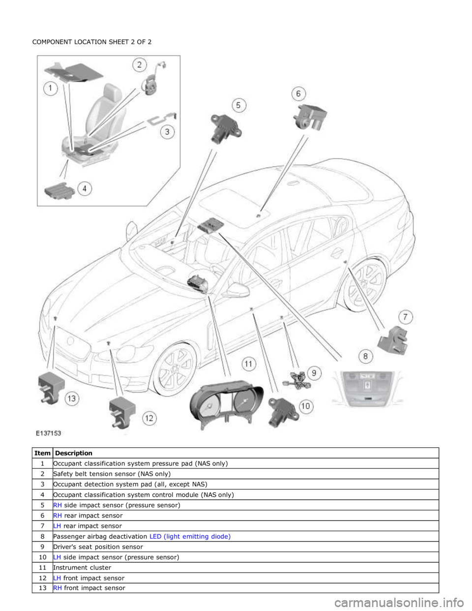
1 Occupant classification system pressure pad (NAS only) 2 Safety belt tension sensor (NAS only) 3 Occupant detection system pad (all, except NAS) 4 Occupant classification system control module (NAS only) 5 RH side impact sensor (pressure sensor) 6 RH rear impact sensor 7 LH rear impact sensor 8 Passenger airbag deactivation LED (light emitting diode) 9 Driver's seat position sensor 10 LH side impact sensor (pressure sensor) 11 Instrument cluster 12 LH front impact sensor 13 RH front impact sensor
Page 2613 of 3039
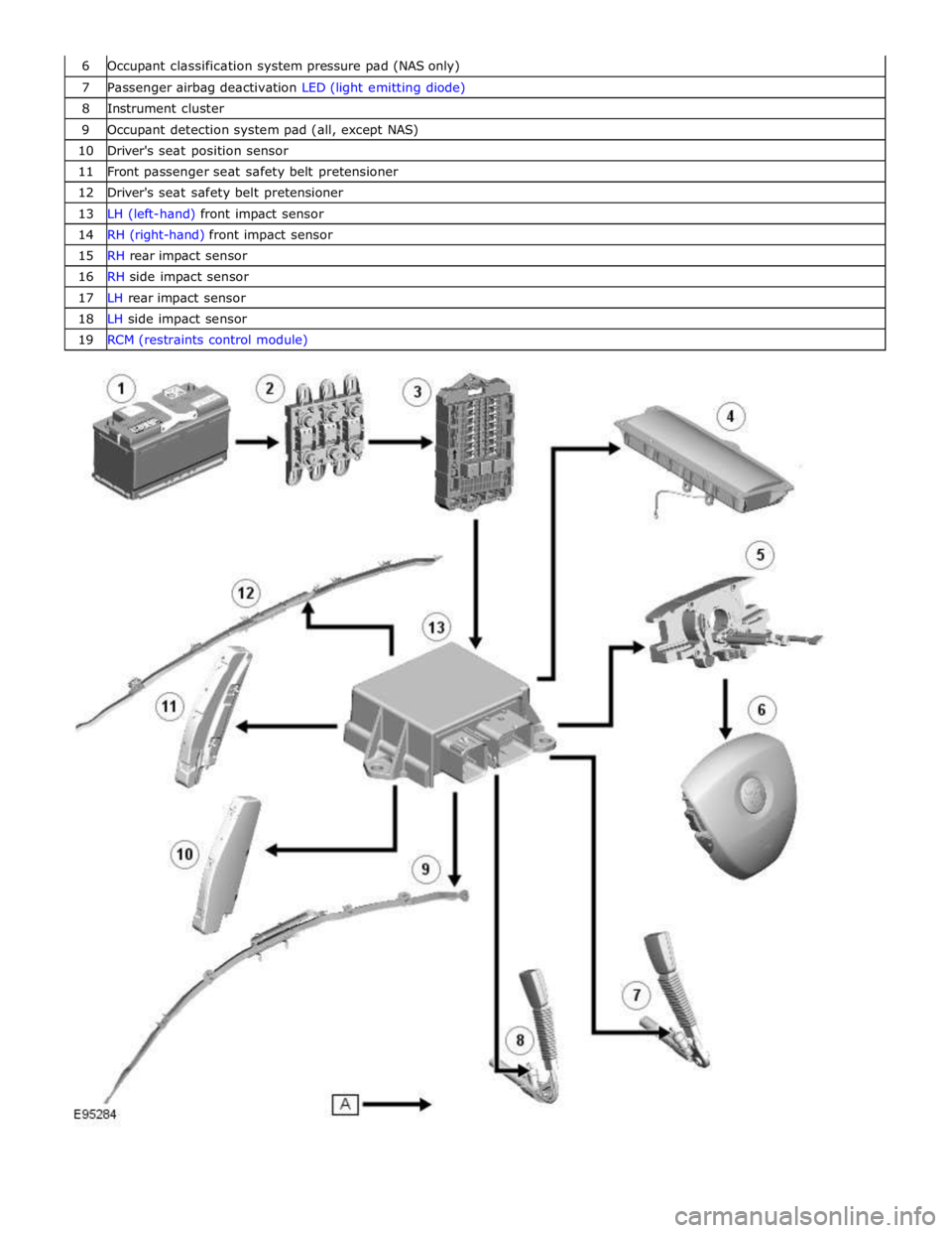
6 Occupant classification system pressure pad (NAS only) 7 Passenger airbag deactivation LED (light emitting diode) 8 Instrument cluster 9 Occupant detection system pad (all, except NAS) 10 Driver's seat position sensor 11 Front passenger seat safety belt pretensioner 12 Driver's seat safety belt pretensioner 13 LH (left-hand) front impact sensor 14 RH (right-hand) front impact sensor 15 RH rear impact sensor 16 RH side impact sensor 17 LH rear impact sensor 18 LH side impact sensor 19 RCM (restraints control module)
Page 2614 of 3039
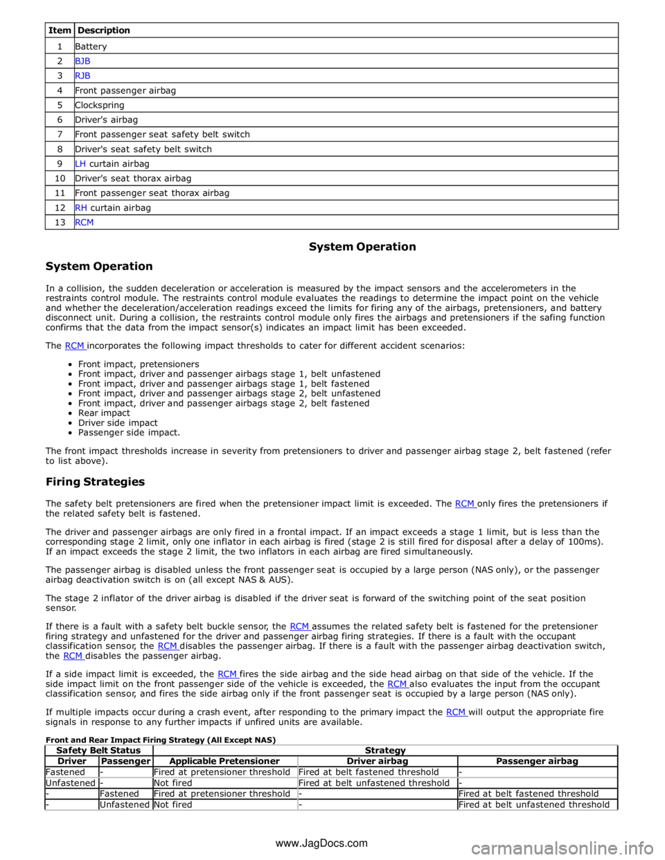
Item Description 1 Battery 2 BJB 3 RJB 4 Front passenger airbag 5 Clockspring 6 Driver's airbag 7 Front passenger seat safety belt switch 8 Driver's seat safety belt switch 9 LH curtain airbag 10 Driver's seat thorax airbag 11 Front passenger seat thorax airbag 12 RH curtain airbag 13 RCM
System Operation System Operation
In a collision, the sudden deceleration or acceleration is measured by the impact sensors and the accelerometers in the
restraints control module. The restraints control module evaluates the readings to determine the impact point on the vehicle
and whether the deceleration/acceleration readings exceed the limits for firing any of the airbags, pretensioners, and battery
disconnect unit. During a collision, the restraints control module only fires the airbags and pretensioners if the safing function
confirms that the data from the impact sensor(s) indicates an impact limit has been exceeded.
The RCM incorporates the following impact thresholds to cater for different accident scenarios: Front impact, pretensioners
Front impact, driver and passenger airbags stage 1, belt unfastened
Front impact, driver and passenger airbags stage 1, belt fastened
Front impact, driver and passenger airbags stage 2, belt unfastened
Front impact, driver and passenger airbags stage 2, belt fastened
Rear impact
Driver side impact
Passenger side impact.
The front impact thresholds increase in severity from pretensioners to driver and passenger airbag stage 2, belt fastened (refer
to list above).
Firing Strategies
The safety belt pretensioners are fired when the pretensioner impact limit is exceeded. The RCM only fires the pretensioners if the related safety belt is fastened.
The driver and passenger airbags are only fired in a frontal impact. If an impact exceeds a stage 1 limit, but is less than the
corresponding stage 2 limit, only one inflator in each airbag is fired (stage 2 is still fired for disposal after a delay of 100ms).
If an impact exceeds the stage 2 limit, the two inflators in each airbag are fired simultaneously.
The passenger airbag is disabled unless the front passenger seat is occupied by a large person (NAS only), or the passenger
airbag deactivation switch is on (all except NAS & AUS).
The stage 2 inflator of the driver airbag is disabled if the driver seat is forward of the switching point of the seat position
sensor.
If there is a fault with a safety belt buckle sensor, the RCM assumes the related safety belt is fastened for the pretensioner firing strategy and unfastened for the driver and passenger airbag firing strategies. If there is a fault with the occupant
classification sensor, the RCM disables the passenger airbag. If there is a fault with the passenger airbag deactivation switch, the RCM disables the passenger airbag.
If a side impact limit is exceeded, the RCM fires the side airbag and the side head airbag on that side of the vehicle. If the side impact limit on the front passenger side of the vehicle is exceeded, the RCM also evaluates the input from the occupant classification sensor, and fires the side airbag only if the front passenger seat is occupied by a large person (NAS only).
If multiple impacts occur during a crash event, after responding to the primary impact the RCM will output the appropriate fire signals in response to any further impacts if unfired units are available.
Front and Rear Impact Firing Strategy (All Except NAS)
Safety Belt Status Strategy Driver Passenger Applicable Pretensioner Driver airbag Passenger airbag Fastened - Fired at pretensioner threshold Fired at belt fastened threshold - Unfastened - Not fired Fired at belt unfastened threshold - - Fastened Fired at pretensioner threshold - Fired at belt fastened threshold - Unfastened Not fired - Fired at belt unfastened threshold www.JagDocs.com
Page 2615 of 3039
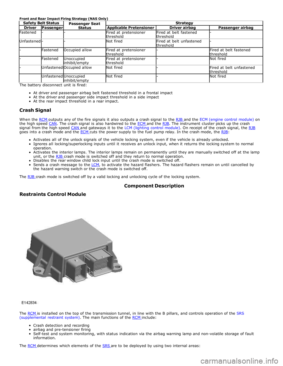
Driver Passenger Applicable Pretensioner Driver airbag Passenger airbag Fastened - -
Fired at pretensioner
threshold Fired at belt fastened
threshold - Unfastened - - Not fired
Fired at belt unfastened
threshold - - Fastened Occupied allow
Fired at pretensioner
threshold -
Fired at belt fastened
threshold - Fastened
Unoccupied inhibit/empty Fired at pretensioner
threshold - Not fired - Unfastened Occupied allow Not fired -
Fired at belt unfastened
threshold Unfastened
Unoccupied inhibit/empty Not fired - Not fired The battery disconnect unit is fired:
At driver and passenger airbag belt fastened threshold in a frontal impact
At the driver and passenger side impact threshold in a side impact
At the rear impact threshold in a rear impact.
Crash Signal
When the RCM outputs any of the fire signals it also outputs a crash signal to the RJB and the ECM (engine control module) on the high speed CAN. The crash signal is also hardwired to the ECM and the RJB. The instrument cluster picks up the crash signal from the high speed CAN and gateways it to the LCM (lighting control module). On receipt of the crash signal, the RJB goes into a crash mode and the ECM cuts the power supply to the fuel pump relay. In the crash mode, the RJB: Activates all of the unlock signals of the vehicle locking system, even if the vehicle is already unlocked.
Ignores all locking/superlocking inputs until it receives an unlock input, when it returns the locking system to normal
operation.
Activates the interior lamps. The interior lamps remain on permanently until they are manually switched off at the lamp
unit, or the RJB crash mode is switched off and they return to normal operation. Disables the rear window child lock input until the crash mode is switched off.
Sends a crash message to the LCM, to activate the hazard flashers. The hazard flashers remain on until cancelled by the hazard warning switch or the crash mode is switched off.
The RJB crash mode is switched off by a valid locking and unlocking cycle of the locking system.
Restraints Control Module Component Description
The RCM is installed on the top of the transmission tunnel, in line with the B pillars, and controls operation of the SRS (supplemental restraint system). The main functions of the RCM include:
Crash detection and recording
airbag and pre-tensioner firing
Self-test and system monitoring, with status indication via the airbag warning lamp and non-volatile storage of fault
information.
The RCM determines which elements of the SRS are to be deployed by using two internal areas:
Page 2620 of 3039
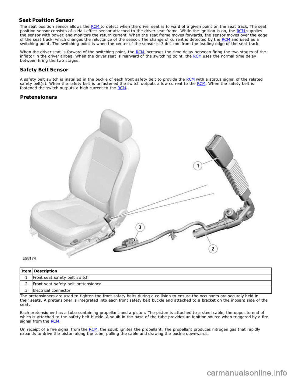
position sensor consists of a Hall effect sensor attached to the driver seat frame. While the ignition is on, the RCM supplies the sensor with power, and monitors the return current. When the seat frame moves forwards, the sensor moves over the edge
of the seat track, which changes the reluctance of the sensor. The change of current is detected by the RCM and used as a switching point. The switching point is when the center of the sensor is 3 ± 4 mm from the leading edge of the seat track.
When the driver seat is forward of the switching point, the RCM increases the time delay between firing the two stages of the inflator in the driver airbag. When the driver seat is rearward of the switching point, the RCM uses the normal time delay between firing the two stages.
Safety Belt Sensor
A safety belt switch is installed in the buckle of each front safety belt to provide the RCM with a status signal of the related safety belt(s). When the safety belt is unfastened the switch outputs a low current to the RCM. When the safety belt is fastened the switch outputs a high current to the RCM.
Pretensioners
Item Description 1 Front seat safety belt switch 2 Front seat safety belt pretensioner 3 Electrical connector The pretensioners are used to tighten the front safety belts during a collision to ensure the occupants are securely held in
their seats. A pretensioner is integrated into each front safety belt buckle and attached to a bracket on the inboard side of the
seat.
Each pretensioner has a tube containing propellant and a piston. The piston is attached to a steel cable, the opposite end of
which is attached to the safety belt buckle. A squib in the base of the tube provides an ignition source when triggered by a fire
signal from the RCM.
On receipt of a fire signal from the RCM, the squib ignites the propellant. The propellant produces nitrogen gas that rapidly expands to drive the piston along the tube, pulling the cable and drawing the buckle downwards.
Page 2684 of 3039
7 RH accelerometer 8 LH accelerometer 9 RJB (rear junction box) 10 BJB (battery junction box)
System Operation
The pedestrian protection system is operational when the vehicle is traveling at speeds between approximately 20 km/h (12.4
mph) and 45 km/h (28 mph). A vehicle speed signal is received by the pedestrian protection system control module over the
high speed CAN bus.
The system is able to determine if contact is made with a pedestrian or another object, such as a traffic cone, using signals
from accelerometers mounted behind the front bumper. When the system determines contact is made with a pedestrian it fires
the actuators to lift the rear of the hood approximately 130 mm within 35 ms of the 'fire' signal.
When an impact condition is registered, the pedestrian protection system control module outputs an impact signal on the high
speed CAN bus. This signal is used by the RJB to initiate the hazard warning lamps. If this occurs, the hazard warning lamp switch is disabled for the remainder of the current ignition cycle.
If the pedestrian protection system control module detects a fault with the system, it outputs a message on the high speed
CAN bus to the instrument cluster message center. On receipt of this, the message center will display the message 'CHECK PEDESTRIAN SYSTEM'.
The pedestrian protection system control module also stores the VIN (vehicle identification number). If a new control module
is fitted to the vehicle the Jaguar approved diagnostic tool must be used to program the unit with the vehicles VIN.
When the vehicle is delivered from the factory the pedestrian protection system is in a 'safe' plant mode. Normal operating
mode should be activated using the Jaguar approved diagnostic tool during the Pre-Delivery Inspection (PDI) prior to delivery
to the customer. For additional information, refer to the PDI manual.
If any damage is caused to the front of the vehicle, be it cosmetic or structural, repairs must be carried out in line with the
processes contained in the workshop manual. Failure to carry out the correct repair process could compromise operation of the
pedestrian protection system. Refer to GTR for the latest information.
The vehicle must be left for 1 minute after disconnecting the battery before any work can be carried out on the pedestrian
protection system.
Failure Mode Detection
In service, if any fault is detected, or any part of the system is recognized as not being present, the message center displays
the warning 'Check Pedestrian System'.
The bonnet deployment actuators are non-serviceable components, and if they must be replaced due to a fault, or due to
having been deployed, or following any other accident, their barcode labels must be read and recorded in the service database
against the vehicle VIN for security purposes.
After deployment of the pedestrian protection system, the vehicle must be stopped as soon as it is safe to do so. The hazard
warning lamps will be activated and can only be switched off by pressing the engine START/STOP button to turn the engine off
and on again. A warning message 'CHECK PEDESTRIAN SYSTEM' will appear on the message center and the vehicle should be
transported to the nearest dealer/authorised repairer. The vehicle must not be driven when the bonnet has been deployed.
NOTE: If the warning message 'CHECK PEDESTRIAN SYSTEM' appears in the message center when the bonnet has not
been deployed, the vehicle should be taken to the nearest dealer/authorised repairer immediately. It can be driven.
If any significant damage occurs to the front bumper it should be inspected by a dealer/authorised repairer as soon as
possible.
CONTROL MODULE Component Description
The control module is mounted below the hood release lever behind the side trim in the left hand front footwell.
The deployment signal is received from the pedestrian protection system control module. The second-generation system
adopted for XF is all-new to Jaguar and, although similar, differs from that introduced on XK by having an accelerometer-based
sensing system rather than a contact-sensing system. The accelerometer-based system is supplied by Bosch. Mounted very
close to the skin of the bumper, it examines the characteristics of vibration waves caused by impact. Its response time is
quicker, because it does not rely on the front of the bumper being loaded. It uses the 'saved' time to make more complex
decisions, and so has fewer error states. The speed of vehicle and the length of the bonnet define the time available to get
the bonnet into its deployed and stabilized position. It is possible, therefore, to create a time-line counting back from the
predicted moment of head impact to the time when the deployment signals need to be sent. That in turn defines a time from
first contact to decision time.
www.JagDocs.com
Page 2707 of 3039
For instance, the crumple zones absorb the bulk of the impact energy. If any unprofessional repair techniques or
methods are used in these areas then this can pose a fundamental threat to vehicle safety.
Hidden damage
As well as looking at external indicators like flaked off paint, it is vital to check for hidden body damage or deformation
that is not visible from the outside. Large attached parts like bumpers and inner fenders often need to be removed to
allow accurate assessment of damage to underlying body parts.
Gap dimensions
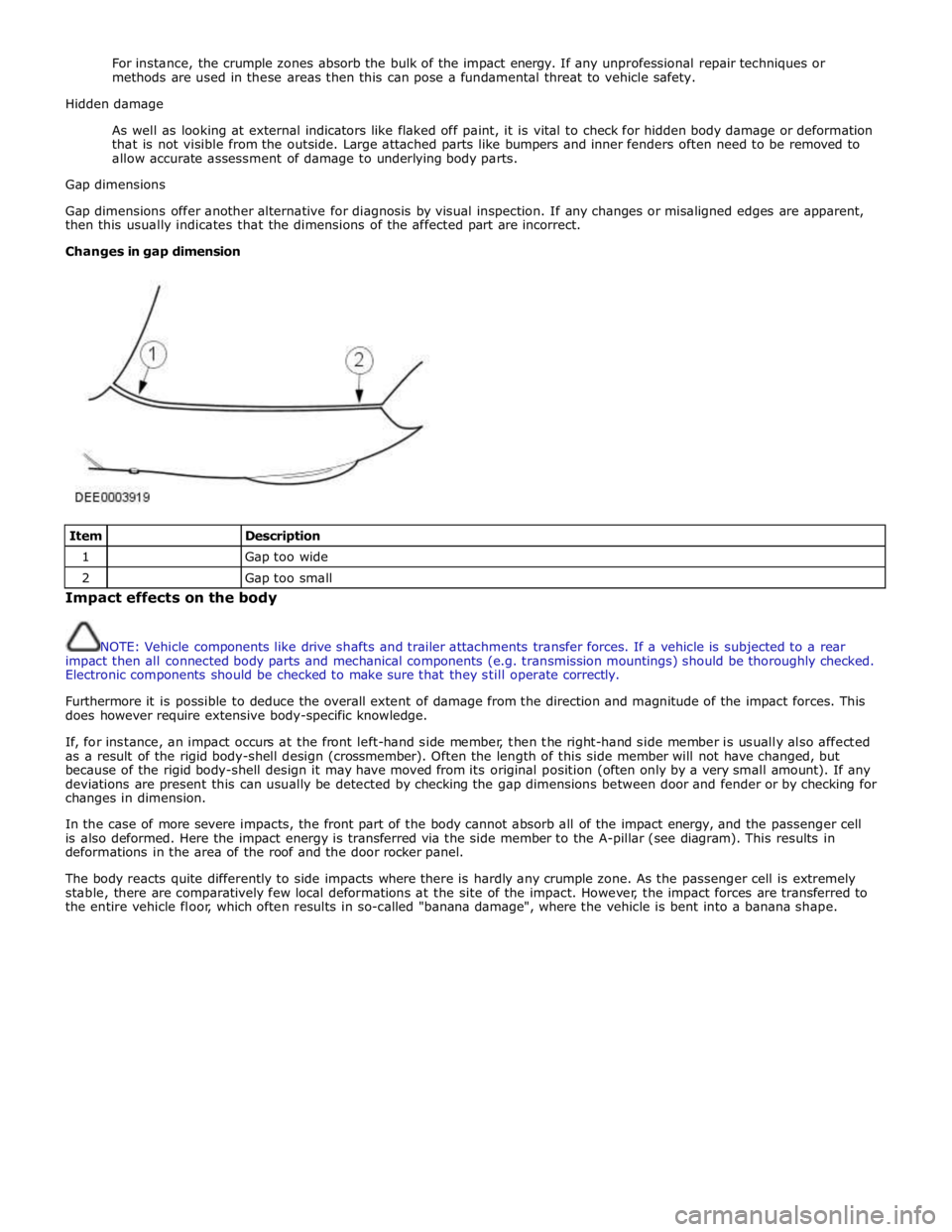
Gap dimensions offer another alternative for diagnosis by visual inspection. If any changes or misaligned edges are apparent,
then this usually indicates that the dimensions of the affected part are incorrect.
Changes in gap dimension
Item
Description 1
Gap too wide 2
Gap too small Impact effects on the body
NOTE: Vehicle components like drive shafts and trailer attachments transfer forces. If a vehicle is subjected to a rear
impact then all connected body parts and mechanical components (e.g. transmission mountings) should be thoroughly checked.
Electronic components should be checked to make sure that they still operate correctly.
Furthermore it is possible to deduce the overall extent of damage from the direction and magnitude of the impact forces. This
does however require extensive body-specific knowledge.
If, for instance, an impact occurs at the front left-hand side member, then the right-hand side member is usually also affected
as a result of the rigid body-shell design (crossmember). Often the length of this side member will not have changed, but
because of the rigid body-shell design it may have moved from its original position (often only by a very small amount). If any
deviations are present this can usually be detected by checking the gap dimensions between door and fender or by checking for
changes in dimension.
In the case of more severe impacts, the front part of the body cannot absorb all of the impact energy, and the passenger cell
is also deformed. Here the impact energy is transferred via the side member to the A-pillar (see diagram). This results in
deformations in the area of the roof and the door rocker panel.
The body reacts quite differently to side impacts where there is hardly any crumple zone. As the passenger cell is extremely
stable, there are comparatively few local deformations at the site of the impact. However, the impact forces are transferred to
the entire vehicle floor, which often results in so-called "banana damage", where the vehicle is bent into a banana shape.