2010 JAGUAR XFR Rear Drive
[x] Cancel search: Rear DrivePage 2414 of 3039

Published: 24-Jan-2013
Glass, Frames and Mechanisms - Glass, Frames and Mechanisms - System
Operation and Component Description
Description and Operation
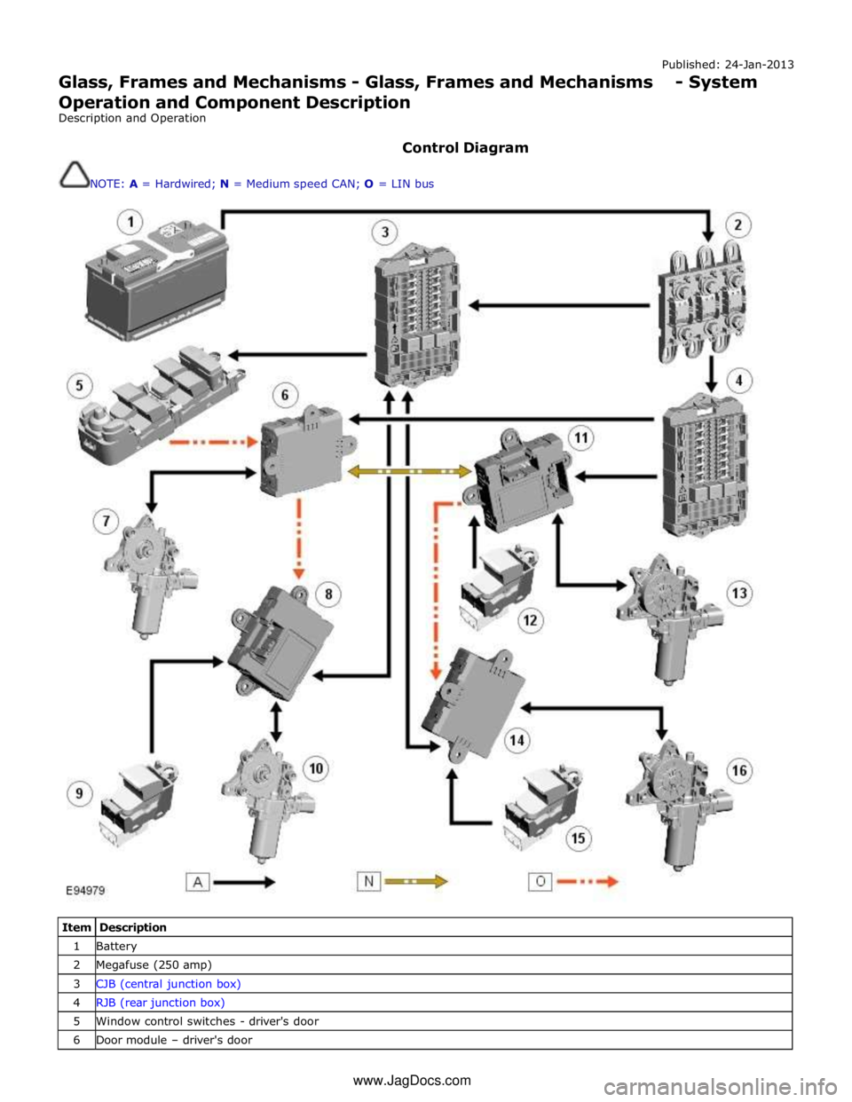
Control Diagram
NOTE: A = Hardwired; N = Medium speed CAN; O = LIN bus
Item Description 1 Battery 2 Megafuse (250 amp) 3 CJB (central junction box) 4 RJB (rear junction box) 5 Window control switches - driver's door 6 Door module – driver's door www.JagDocs.com
Page 2415 of 3039

7 Window regulator motor – driver's door 8 Door module – LH (left-hand) rear passenger 9 Window control switch - LH rear passenger 10 Window regulator motor – LH rear passenger 11 Door module – front passenger 12 Window control switches - front passenger 13 Window regulator motor – front passenger 14 Door module – RH (right-hand) rear passenger 15 Window control switch - RH rear passenger 16 Window regulator motor – RH rear passenger
Door Windows System Operation
All windows can be operated individually, or by the driver’s window control switch. The operation of the windows is proportional
to the switch activation. All windows can be controlled by ‘one touch’ in an upward or downward direction. When the ‘one
touch’ operation is activated in the upwards direction ‘pinch protection‘ is enabled. If a pinch condition is detected the window
will automatically stop and travel downwards to a pre-determined position.
When the rear window ‘one touch’ operation is activated in the downward direction, the window will drop a limited way down.
This is the comfort setting to achieve optimum noise levels when vehicle is in motion with rear windows open. Further ‘one
touch’ operation will drop the window all the way down. (Only applies to vehicles post VIN R99740) The ‘one touch’ operation
to activate the upward direction will fully close the window.
Electric window operation is enabled while the ignition is in power mode 4 and 6. When the switches in the driver's door are
used to operate the passenger windows, the driver's door module outputs a related message on the LIN (local interconnect
network) bus and medium speed CAN (controller area network) bus. The passenger door module responds to the message by
operating the appropriate window. When the child lock is engaged, the rear door modules ignore inputs from the rear window
switches.
End of travel shut off
End of travel shut-off for the window motors is determined by monitoring the current draw of the motors. Each time it switches
on a window motor, the door module measures the window motor current for a preset time. The maximum value measured
within that time is stored as the switch-on current. When the window motor current next exceeds the switch-on current, the
door module assumes the window has reached the end of its travel and switches off the power supply to the window motor
even if a window switch is still being activated.
Anti-trap
The anti-trap function is enabled for window closing in both the inching and one-shot modes. If the anti-trap feature is
activated while a window is closing, the window motor is reversed for a preset period.
A Hall sensor, located in the window regulator motor, monitors the speed of the motor and if the speed decreases below a set
threshold, indicating an obstruction, the power feed to the motor is reversed so the window goes back down for preset time.
In an emergency the anti-trap function can be overridden by holding the window switch in the one-shot closed position.
After the battery has been disconnected it is necessary to initialize the door window motors to be able to operate the one-shot
up function.
Windshield Component Description
The windshield, manufactured from 5mm laminated green-tinted glass is positioned to the vehicle's body by two locator pins,
one in each top corner of the windshield. This allows for centralizing movement of the windshield across the car upon fitment.
The base of the windshield carries a leaf-screen retainer. The windshield is bonded and sealed to the vehicle body aperture
using Polyurethane (PU) adhesive. The windshield finisher is a three-sided extruded flip, taped onto the inner surface of the
glass; this helps to centralize the glass in the aperture.
Two variants of windshield are available:
standard, and
heated.
Refer to: Control Components (412-01 Climate Control, Description and Operation).
Interior Mirror and Rain Sensor
The interior mirror and rain sensor mounting positions are located at the top of the windshield.
Refer to: Wipers and Washers (501-16 Wipers and Washers, Description and Operation).
Page 2416 of 3039

Rear Window
The rear window, manufactured from toughened 4mm green-tinted glass, is positioned to the vehicle's body by two locator
pins, one in each top corner of the windshield. This allows for the centralizing movement of the windshield across the car upon
fitment. The window is bonded and sealed to the vehicle body aperture using PU adhesive. The window finisher is a
three-sided extruded flip, taped onto the inner surface of the glass; this helps to centralize the glass in the aperture.
The heated rear window grid wire and antennas are incorporated in the rear window. There are two derivatives of rear window
dependant on the TV antenna specification.
Refer to: Video System (415-01, Description and Operation).
Door Windows
The door windows are manufactured from 4.85mm green-tinted toughened glass. The driver and passenger windows are
electrically operated, and are raised and lowered by a cable mechanism; the rear glass sections in the rear doors are fixed
units.
All windows can be operated individually, or by the driver's window control switch. The operation of the windows is proportional
to the switch activation. The driver window can be controlled by 'one touch' in an upward or downward direction. When the 'one
touch' operation is activated in the upwards direction an anti-trap sensor is automatically checked prior to the window closing.
If the anti-trap sensor is inoperative the window will not close. When the anti-trap sensor detects an obstacle in the window's
path, the upward travel of the window will automatically cease. Downward travel of the window will begin and then stop when a
preset time has elapsed.
Page 2418 of 3039

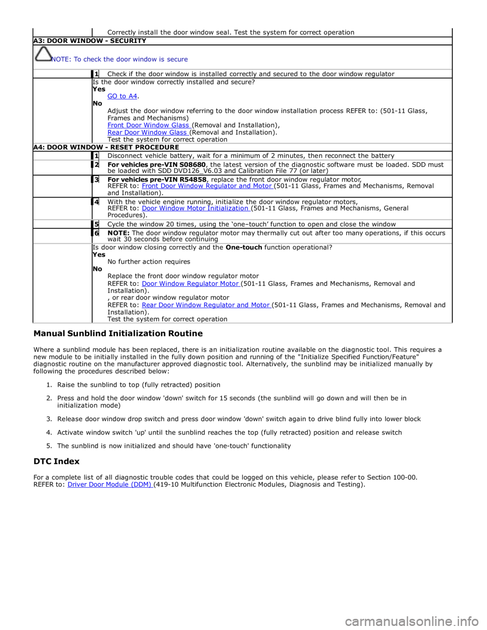
Correctly install the door window seal. Test the system for correct operation A3: DOOR WINDOW - SECURITY
NOTE: To check the door window is secure 1 Check if the door window is installed correctly and secured to the door window regulator Is the door window correctly installed and secure?
Yes
GO to A4. No
Adjust the door window referring to the door window installation process REFER to: (501-11 Glass,
Frames and Mechanisms)
Front Door Window Glass (Removal and Installation), Rear Door Window Glass (Removal and Installation). Test the system for correct operation A4: DOOR WINDOW - RESET PROCEDURE 1 Disconnect vehicle battery, wait for a minimum of 2 minutes, then reconnect the battery 2 For vehicles pre-VIN S08680, the latest version of the diagnostic software must be loaded. SDD must be loaded with SDD DVD126_V6.03 and Calibration File 77 (or later) 3 For vehicles pre-VIN R54858, replace the front door window regulator motor, REFER to: Front Door Window Regulator and Motor (501-11 Glass, Frames and Mechanisms, Removal and Installation). 4 With the vehicle engine running, initialize the door window regulator motors, REFER to: Door Window Motor Initialization (501-11 Glass, Frames and Mechanisms, General Procedures). 5 Cycle the window 20 times, using the ‘one–touch’ function to open and close the window 6 NOTE: The door window regulator motor may thermally cut out after too many operations, if this occurs wait 30 seconds before continuing Is door window closing correctly and the One-touch function operational?
Yes
No further action requires
No
Replace the front door window regulator motor
REFER to: Door Window Regulator Motor (501-11 Glass, Frames and Mechanisms, Removal and Installation).
, or rear door window regulator motor
REFER to: Rear Door Window Regulator and Motor (501-11 Glass, Frames and Mechanisms, Removal and Installation).
Test the system for correct operation Manual Sunblind Initialization Routine
Where a sunblind module has been replaced, there is an initialization routine available on the diagnostic tool. This requires a
new module to be initially installed in the fully down position and running of the "Initialize Specified Function/Feature"
diagnostic routine on the manufacturer approved diagnostic tool. Alternatively, the sunblind may be initialized manually by
following the procedures described below:
1. Raise the sunblind to top (fully retracted) position
2. Press and hold the door window 'down' switch for 15 seconds (the sunblind will go down and will then be in
initialization mode)
3. Release door window drop switch and press door window 'down' switch again to drive blind fully into lower block
4. Activate window switch 'up' until the sunblind reaches the top (fully retracted) position and release switch
5. The sunblind is now initialized and should have 'one-touch' functionality
DTC Index
For a complete list of all diagnostic trouble codes that could be logged on this vehicle, please refer to Section 100-00.
REFER to: Driver Door Module (DDM) (419-10 Multifunction Electronic Modules, Diagnosis and Testing).
Page 2491 of 3039

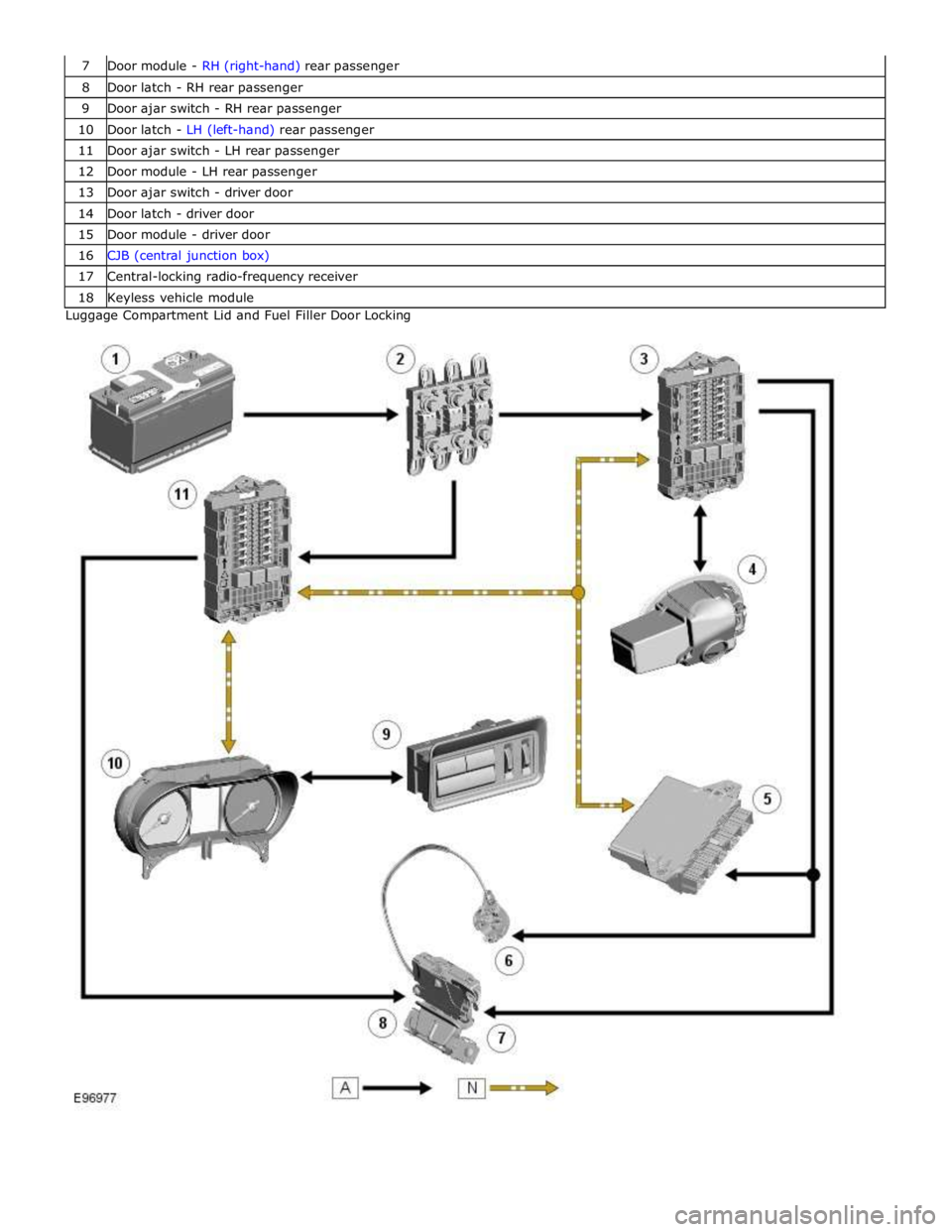
8 Door latch - RH rear passenger 9 Door ajar switch - RH rear passenger 10 Door latch - LH (left-hand) rear passenger 11 Door ajar switch - LH rear passenger 12 Door module - LH rear passenger 13 Door ajar switch - driver door 14 Door latch - driver door 15 Door module - driver door 16 CJB (central junction box) 17 Central-locking radio-frequency receiver 18 Keyless vehicle module Luggage Compartment Lid and Fuel Filler Door Locking
Page 2493 of 3039

Item Description Note: A = Hardwired; N = Medium speed CAN 1 Battery 2 Megafuse (250 A) 3 CJB 4 Radio frequency receiver 5 Keylesss vehicle module 6 Door handle, lock/unlock switch and antenna - front passenger 7 Door latch, fast latch - front passenger 8 Door latch, fast latch - RH rear passenger 9 Door handle, lock/unlock switch and antenna - RH rear passenger 10 Door latch, fast latch - LH rear passenger 11 Door handle, lock/unlock switch and antenna - LH rear passenger 12 Door latch, fast latch - driver door 13 Door handle, lock/unlock switch and antenna - driver door
System Operation
The hinged panels are secured with latches and strikers. A remotely operated central locking system controls the locking and
unlocking of the door and luggage compartment latches. A radio frequency Smart Key allows the vehicle to be locked and
unlocked by pressing the appropriate handset buttons. Two levels of central locking system are available: remote central
locking and an optional passive entry system.
The passive entry and associated passive start system allows the driver to unlock and start the vehicle without using a vehicle
key in a door-lock or ignition switch. The passive entry system is an optional fitment while the passive start system is a
standard fitment on all vehicles. The passive start system is combined with the passive anti-theft immobilization system.
Refer to: Anti-Theft - Passive (419-01B Anti-Theft - Passive, Description and Operation).
Emergency access to the vehicle is provided by two concealed key barrels: one located in the front left-hand door handle and
one located on the underside of the luggage compartment lid finisher. An emergency, removable key blade is fitted into the
Smart Key.
Operation of either key barrel unlocks the vehicle but does not disarm the alarm system. The key barrels in the door and
luggage compartment lid are concealed by a plastic cover which can be removed by inserting the blade of the emergency key
into a slot in the cover.
Locking and unlocking conditions using the emergency key in the door key barrel:
If the alarm is not armed the vehicle can be centrally unlocked.
If the alarm is armed the door only can be opened and the alarm will be triggered.
The vehicle cannot be double locked or the alarm system armed using the emergency key.
The vehicle can be centrally locked and unlocked from inside using the interior handle release levers on the front doors only.
Central locking and unlocking can also be performed using lock and unlock buttons on the vehicle's fascia. The driver can select
locking options, single point entry or drive away locking for example, from a menu available on the touch screen.
Central Locking – Radio Frequency Remote System
The radio frequency central locking system, provides locking and unlocking of the vehicle from inside and outside of the
vehicle. The system is operated using buttons on the Smart Key, which transmits radio frequency signals to the central locking
radio frequency receiver.
The system provides additional security by double-locking the doors from outside the vehicle if the lock button, on the Smart
Key, is pressed twice within 3 seconds; this function is not applicable in North American Specification (NAS) and Japanese
markets.
Additional buttons on the Smart Key provide for the convenience operation of the luggage compartment lid release, headlamp
delay and panic alarm functions. A global open or close feature is also available in certain markets using the lock/unlock
buttons.
Passive Entry
On vehicles fitted with the optional passive entry system, the vehicle can be unlocked without the use of a key blade or
pressing buttons on the Smart Key. The Smart Key operates the passive entry system in addition to the passive start system.
Refer to: Anti-Theft - Passive (419-01B Anti-Theft - Passive, Description and Operation).
The passive entry system is controlled by the keyless vehicle module and five low frequency antennas. One antenna located in
each door handle and one antenna located behind the rear bumper cover.
When a vehicle door handle is pulled to the first five-percent of its travel and the Smart Key is within one meter of the handle;
the Smart Key receives the low-frequency signal transmitted from the keyless vehicle module. The Smart Key responds with a
radio frequency transmission of its authorization code. The radio frequency signal is received by the central locking radio-
frequency receiver and passed to the keyless vehicle module which checks and approves the code as valid. Once the handle is
Page 2494 of 3039

door modules.
Locking of the vehicle is performed by pressing one of the buttons located on each exterior door handle, with the Smart Key
within a one meter range of the vehicle. When the door handle button is pressed, the keyless vehicle module transmits a
low-frequency signal via the low-frequency handle antenna to the Smart Key. The Smart Key transmits a radio frequency signal
which is verified by the keyless vehicle module and allows the doors to be locked or double locked and the alarm system to be
armed.
To double lock the vehicle, the button on the exterior door handle must be pressed twice within three seconds, with the Smart
Key within one meter range of the vehicle.
If a door, engine-compartment lid or the luggage compartment lid is ajar when an attempt to lock the vehicle is made, an error
tone is emitted and no locking action will occur.
Refer to: Anti-Theft - Active (419-01A Anti-Theft - Active, Description and Operation).
Engine Compartment Lid Latches Component Description
Two engine-compartment lid latches are located on the front crossmember. An engine-compartment lid release lever is located
below the instrument panel on the left-hand 'A' pillar and is connected with a cable to the latches. An engine-compartment lid
ajar switch is integrated in the engine-compartment lid latch.
Door Latches
The door latches are located at the rear of each door and engage with a striker on the adjacent pillar. Each door latch motor
assembly contains micro-switches for lock, unlock and door ajar. Motors provide for the central door locking and the double
locking feature. The electrical control for the door latch components is provided by the CJB and RJB via the driver's and
passenger door modules.
The interior door handles are connected by a cable to the latch release mechanisms. The interior door handles also incorporate
a locking facility to allow the doors to be locked from inside the vehicle when all the doors are closed. If a door is ajar the
locking feature is inhibited.
Luggage Compartment Lid Latch
The luggage compartment latch is attached to the bottom of the lid. The latch can be released electrically by pressing the
interior release button located on the outboard side of driver's lower knee bolster; a release button is also provided on the
Smart Key. There is also a release switch on the underside of the luggage compartment lid finisher.
On NAS vehicles an emergency release cable is attached to the latch. This allows the latch to be manually opened by pulling a
handle located in the luggage compartment lid interior trim.
Fuel Filler Door
The fuel filler door is electrically locked by a motor located on the fuel door housing. The fuel door is locked when the vehicle
is locked and alarmed. The fuel door can be opened when the vehicle is unlocked or locked:
via an interior handle,
via drive-a-way locking,
via the lock switch on the fascia,
via the external door key barrel. www.JagDocs.com
Page 2503 of 3039

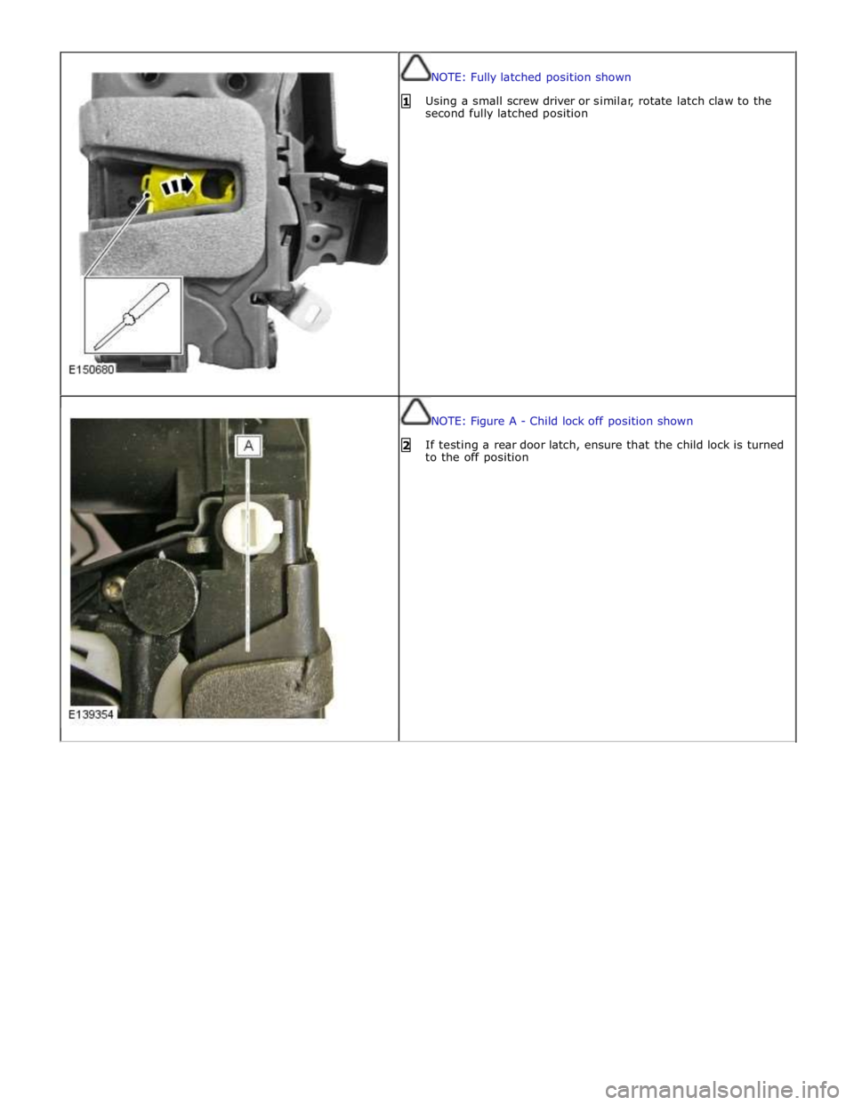
NOTE: Fully latched position shown
1 Using a small screw driver or similar, rotate latch claw to the
second fully latched position
NOTE: Figure A - Child lock off position shown
2 If testing a rear door latch, ensure that the child lock is turned
to the off position