Page 998 of 3039
20.
21.
22.
CAUTIONS:
Be prepared to collect escaping fluids.
Make sure that all openings are sealed. Use new blanking caps.
Discard the fuel pipes.
Page 1009 of 3039
23.
24.
25. Loosen the Torx screws half a turn each.
CAUTIONS:
Install new high-pressure fuel supply lines.
Lubricate only the union threads with clean engine oil.
NOTES:
Remove and discard the blanking caps.
Install the bolt and unions fully finger tight before final tightening.
Page 1010 of 3039
26.
27.
28. CAUTION: Care must be taken when positioning the fuel rail
high-pressure fuel pump cover to one side.
NOTE: Fuel rail high-pressure fuel pump cover shown removed for
clarity.
Torque: 11 Nm
CAUTION: Care must be taken when positioning the fuel rail
high-pressure fuel pump cover to one side.
NOTE: Fuel rail high-pressure fuel pump cover shown removed for
clarity.
Torque: 11 Nm
NOTES:
Do not tighten at this stage.
Remove and discard the blanking caps.
Page 1187 of 3039

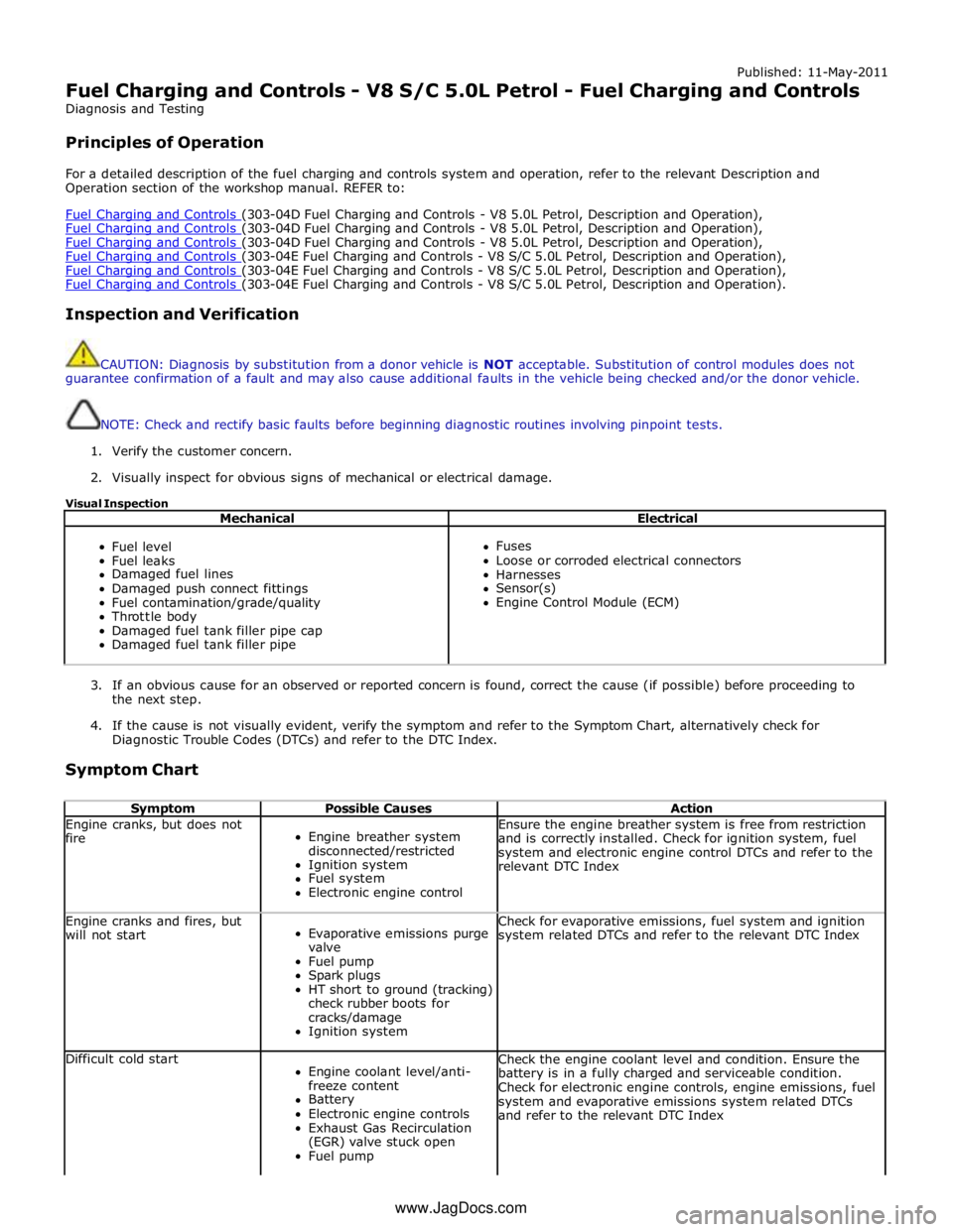
Published: 11-May-2011
Fuel Charging and Controls - V8 S/C 5.0L Petrol - Fuel Charging and Controls
Diagnosis and Testing
Principles of Operation
For a detailed description of the fuel charging and controls system and operation, refer to the relevant Description and
Operation section of the workshop manual. REFER to:
Fuel Charging and Controls (303-04D Fuel Charging and Controls - V8 5.0L Petrol, Description and Operation), Fuel Charging and Controls (303-04D Fuel Charging and Controls - V8 5.0L Petrol, Description and Operation), Fuel Charging and Controls (303-04D Fuel Charging and Controls - V8 5.0L Petrol, Description and Operation), Fuel Charging and Controls (303-04E Fuel Charging and Controls - V8 S/C 5.0L Petrol, Description and Operation), Fuel Charging and Controls (303-04E Fuel Charging and Controls - V8 S/C 5.0L Petrol, Description and Operation), Fuel Charging and Controls (303-04E Fuel Charging and Controls - V8 S/C 5.0L Petrol, Description and Operation).
Inspection and Verification
CAUTION: Diagnosis by substitution from a donor vehicle is NOT acceptable. Substitution of control modules does not
guarantee confirmation of a fault and may also cause additional faults in the vehicle being checked and/or the donor vehicle.
NOTE: Check and rectify basic faults before beginning diagnostic routines involving pinpoint tests.
1. Verify the customer concern.
2. Visually inspect for obvious signs of mechanical or electrical damage.
Visual Inspection
Mechanical Electrical
Fuel level
Fuel leaks
Damaged fuel lines
Damaged push connect fittings
Fuel contamination/grade/quality
Throttle body
Damaged fuel tank filler pipe cap
Damaged fuel tank filler pipe
Fuses
Loose or corroded electrical connectors
Harnesses
Sensor(s)
Engine Control Module (ECM)
3. If an obvious cause for an observed or reported concern is found, correct the cause (if possible) before proceeding to
the next step.
4. If the cause is not visually evident, verify the symptom and refer to the Symptom Chart, alternatively check for
Diagnostic Trouble Codes (DTCs) and refer to the DTC Index.
Symptom Chart
Symptom Possible Causes Action Engine cranks, but does not
fire
Engine breather system
disconnected/restricted
Ignition system
Fuel system
Electronic engine control Ensure the engine breather system is free from restriction
and is correctly installed. Check for ignition system, fuel
system and electronic engine control DTCs and refer to the
relevant DTC Index Engine cranks and fires, but
will not start
Evaporative emissions purge
valve
Fuel pump
Spark plugs
HT short to ground (tracking)
check rubber boots for
cracks/damage
Ignition system Check for evaporative emissions, fuel system and ignition
system related DTCs and refer to the relevant DTC Index Difficult cold start
Engine coolant level/anti-
freeze content
Battery
Electronic engine controls
Exhaust Gas Recirculation
(EGR) valve stuck open
Fuel pump Check the engine coolant level and condition. Ensure the
battery is in a fully charged and serviceable condition.
Check for electronic engine controls, engine emissions, fuel
system and evaporative emissions system related DTCs
and refer to the relevant DTC Index www.JagDocs.com
Page 1192 of 3039
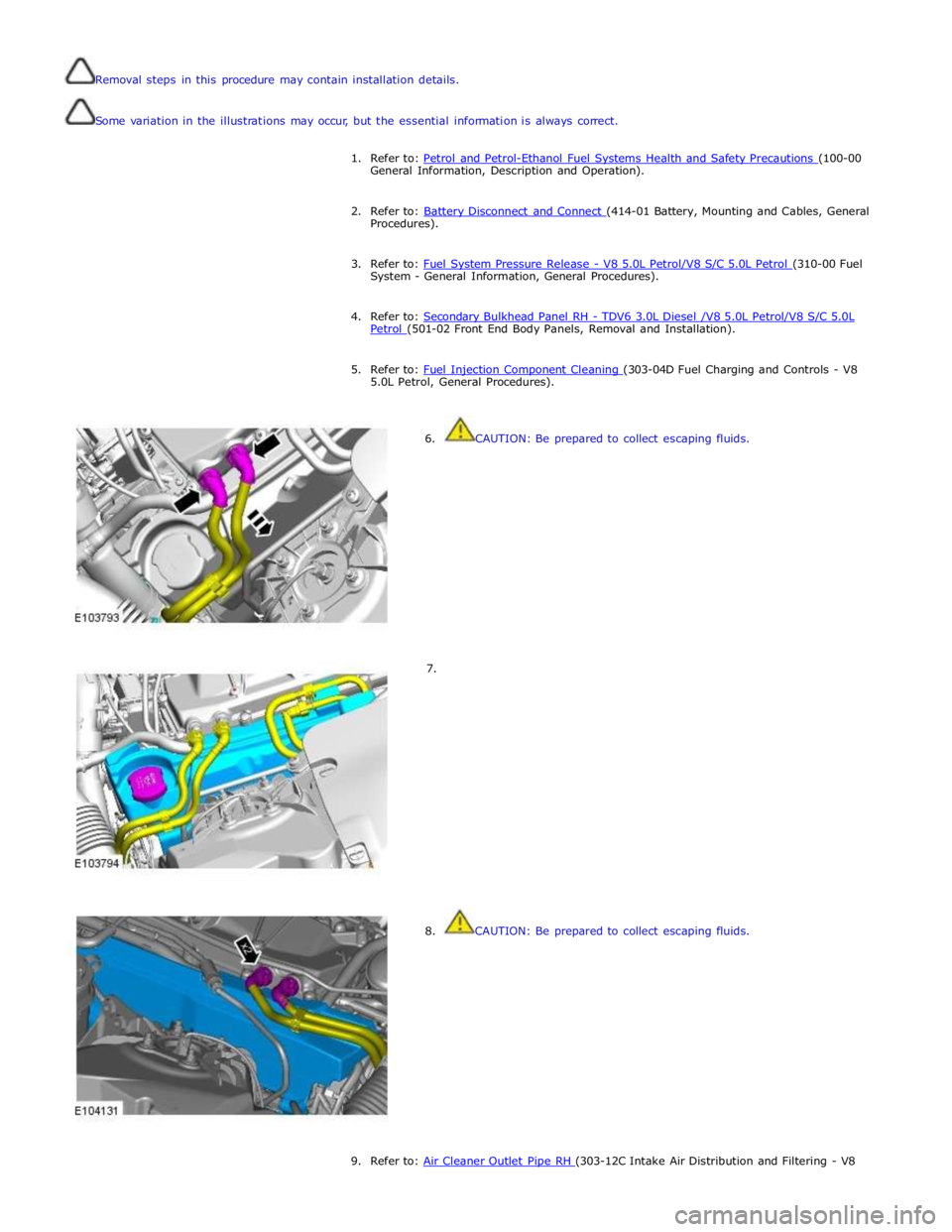
Removal steps in this procedure may contain installation details.
Some variation in the illustrations may occur, but the essential information is always correct.
1. Refer to: Petrol and Petrol-Ethanol Fuel Systems Health and Safety Precautions (100-00 General Information, Description and Operation).
2. Refer to: Battery Disconnect and Connect (414-01 Battery, Mounting and Cables, General Procedures).
3. Refer to: Fuel System Pressure Release - V8 5.0L Petrol/V8 S/C 5.0L Petrol (310-00 Fuel System - General Information, General Procedures).
4. Refer to: Secondary Bulkhead Panel LH - TDV6 3.0L Diesel /V8 5.0L Petrol/V8 S/C 5.0L Petrol (501-02 Front End Body Panels, Removal and Installation).
5. Refer to: Fuel Injection Component Cleaning (303-04D Fuel Charging and Controls - V8 5.0L Petrol, General Procedures).
6. CAUTION: Be prepared to collect escaping fluids.
7.
8. CAUTION: Be prepared to collect escaping fluids. www.JagDocs.com
Page 1203 of 3039

Removal steps in this procedure may contain installation details.
Some variation in the illustrations may occur, but the essential information is always correct.
1. Refer to: Petrol and Petrol-Ethanol Fuel Systems Health and Safety Precautions (100-00 General Information, Description and Operation).
2. Refer to: Battery Disconnect and Connect (414-01 Battery, Mounting and Cables, General Procedures).
3. Refer to: Fuel System Pressure Release - V8 5.0L Petrol/V8 S/C 5.0L Petrol (310-00 Fuel System - General Information, General Procedures).
4. Refer to: Secondary Bulkhead Panel RH - TDV6 3.0L Diesel /V8 5.0L Petrol/V8 S/C 5.0L Petrol (501-02 Front End Body Panels, Removal and Installation).
5. Refer to: Fuel Injection Component Cleaning (303-04D Fuel Charging and Controls - V8 5.0L Petrol, General Procedures).
6. CAUTION: Be prepared to collect escaping fluids.
7.
8. CAUTION: Be prepared to collect escaping fluids.
9. Refer to: Air Cleaner Outlet Pipe RH (303-12C Intake Air Distribution and Filtering - V8
Page 1217 of 3039

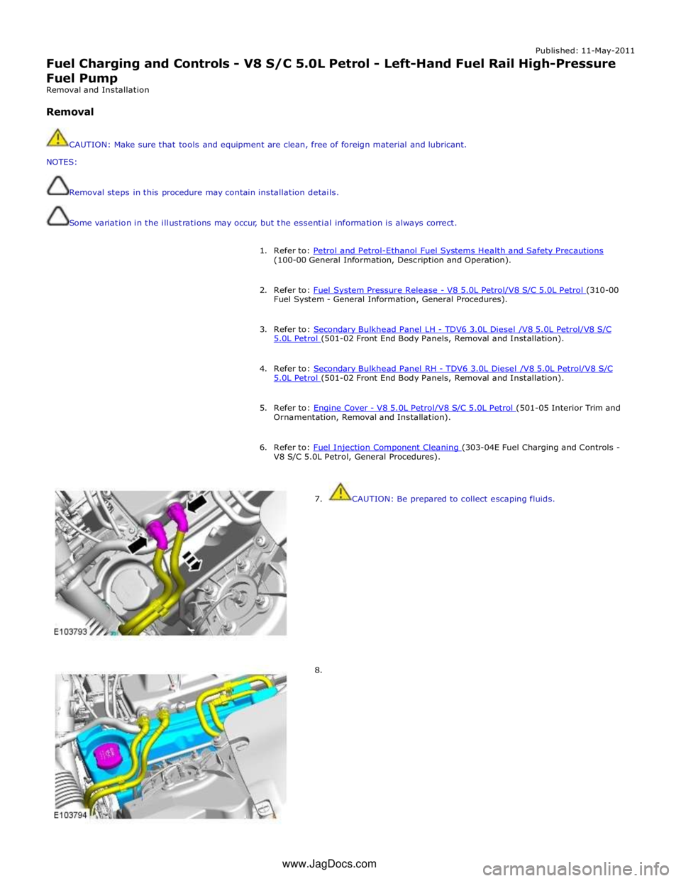
Published: 11-May-2011
Fuel Charging and Controls - V8 S/C 5.0L Petrol - Left-Hand Fuel Rail High-Pressure
Fuel Pump Removal and Installation
Removal
CAUTION: Make sure that tools and equipment are clean, free of foreign material and lubricant.
NOTES:
Removal steps in this procedure may contain installation details.
Some variation in the illustrations may occur, but the essential information is always correct.
1. Refer to: Petrol and Petrol-Ethanol Fuel Systems Health and Safety Precautions (100-00 General Information, Description and Operation).
2. Refer to: Fuel System Pressure Release - V8 5.0L Petrol/V8 S/C 5.0L Petrol (310-00 Fuel System - General Information, General Procedures).
3. Refer to: Secondary Bulkhead Panel LH - TDV6 3.0L Diesel /V8 5.0L Petrol/V8 S/C 5.0L Petrol (501-02 Front End Body Panels, Removal and Installation). 4. Refer to: Secondary Bulkhead Panel RH - TDV6 3.0L Diesel /V8 5.0L Petrol/V8 S/C 5.0L Petrol (501-02 Front End Body Panels, Removal and Installation). 5. Refer to: Engine Cover - V8 5.0L Petrol/V8 S/C 5.0L Petrol (501-05 Interior Trim and Ornamentation, Removal and Installation).
6. Refer to: Fuel Injection Component Cleaning (303-04E Fuel Charging and Controls - V8 S/C 5.0L Petrol, General Procedures).
7. CAUTION: Be prepared to collect escaping fluids.
8. www.JagDocs.com
Page 1220 of 3039
18.
19.
20. NOTE: Engine shown removed for clarity.
NOTE: Engine shown removed for clarity.
CAUTIONS:
Remove and discard the high-pressure fuel supply lines.
Be prepared to collect escaping fluids.
Make sure that all openings are sealed. Use new blanking caps.
NOTE: Engine shown removed for clarity.