Page 1571 of 3039
17.
18. NOTE: Vehicles without Diesel engine shown, vehicles
with Diesel engine similar.
Remove the special tool.
CAUTION: Make sure the new fuel tank drain port
sealing cap is correctly installed. Failure to follow this
instruction may result in damage to the vehicle.
NOTE: Vehicles without Diesel engine shown, vehicles
with Diesel engine similar.
Install a new fuel tank drain port sealing cap.
19.
Install the floor aperture cover.
Page 1580 of 3039
Fuel system Electronic returnless fuel system (ERFS) Fuel tank Multi layer plastic Fuel tank sender unit Mounted on the body of the fuel pump Fuel filter Located in the fuel tank Fuel pump Electric,located in the fuel tank System pressure 4.5 bar - 65 lbf/in2 Capacities Liters Fuel tank capacity 71.1 (total) / 69.5 (useable) Torque Specifications
Item Nm lb-ft lb-in Fuel tank filler pipe bracket retaining nut 9 - 80 Fuel tank filler pipe bracket retaining bolt 9 - 80 Fuel tank support strap retaining bolts 35 26 - Fuel / vapor tube bracket retaining bolt in engine compartment 5 - 44 Fuel / vapor tube bracket to underbody retaining bolts 7 - 62 Fuel pump and sender unit locking ring 250 184 -
Page 1582 of 3039
10 FPDM (fuel pump driver module) 11 Fuel filler pipe 12 Fuel filler cap and lanyard 13 Charcoal canister 14 Pipe - EVAP charcoal canister to purge valve COMPONENT LOCATION - NORTH AMERICAN SPECIFICATION (NAS)
Item Description 1 Fuel feed pipe connection 2 EVAP pipe connection 3 Manifold 4 LP sensor 5 Fuel feed pipe 6 Fuel vapor vent valve
Page 1583 of 3039
8 Fuel tank 9 Fuel filler hose 10 FPDM 11 Anti-trickle valve 12 Fuel filler cap and lanyard 13 DMTL filter 14 Fuel filler pipe 15 Charcoal canister 16 DMTL pump 17 Pipe - EVAP charcoal canister to purge valve
Page 1588 of 3039

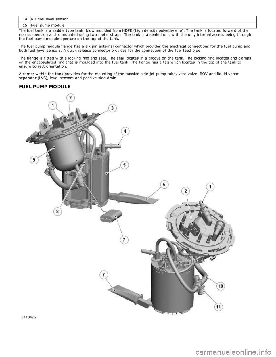
15 Fuel pump module The fuel tank is a saddle type tank, blow moulded from HDPE (high density polyethylene). The tank is located forward of the
rear suspension and is mounted using two metal straps. The tank is a sealed unit with the only internal access being through
the fuel pump module aperture on the top of the tank.
The fuel pump module flange has a six pin external connector which provides the electrical connections for the fuel pump and
both fuel level sensors. A quick release connector provides for the connection of the fuel feed pipe.
The flange is fitted with a locking ring and seal. The seal locates in a groove on the tank. The locking ring locates and clamps
on the encapsulated ring that is moulded into the fuel tank. The flange has a tag which locates in the top of the tank to
ensure correct orientation.
A carrier within the tank provides for the mounting of the passive side jet pump tube, vent valve, ROV and liquid vapor
separator (LVS), level sensors and passive side drain.
FUEL PUMP MODULE
Page 1591 of 3039

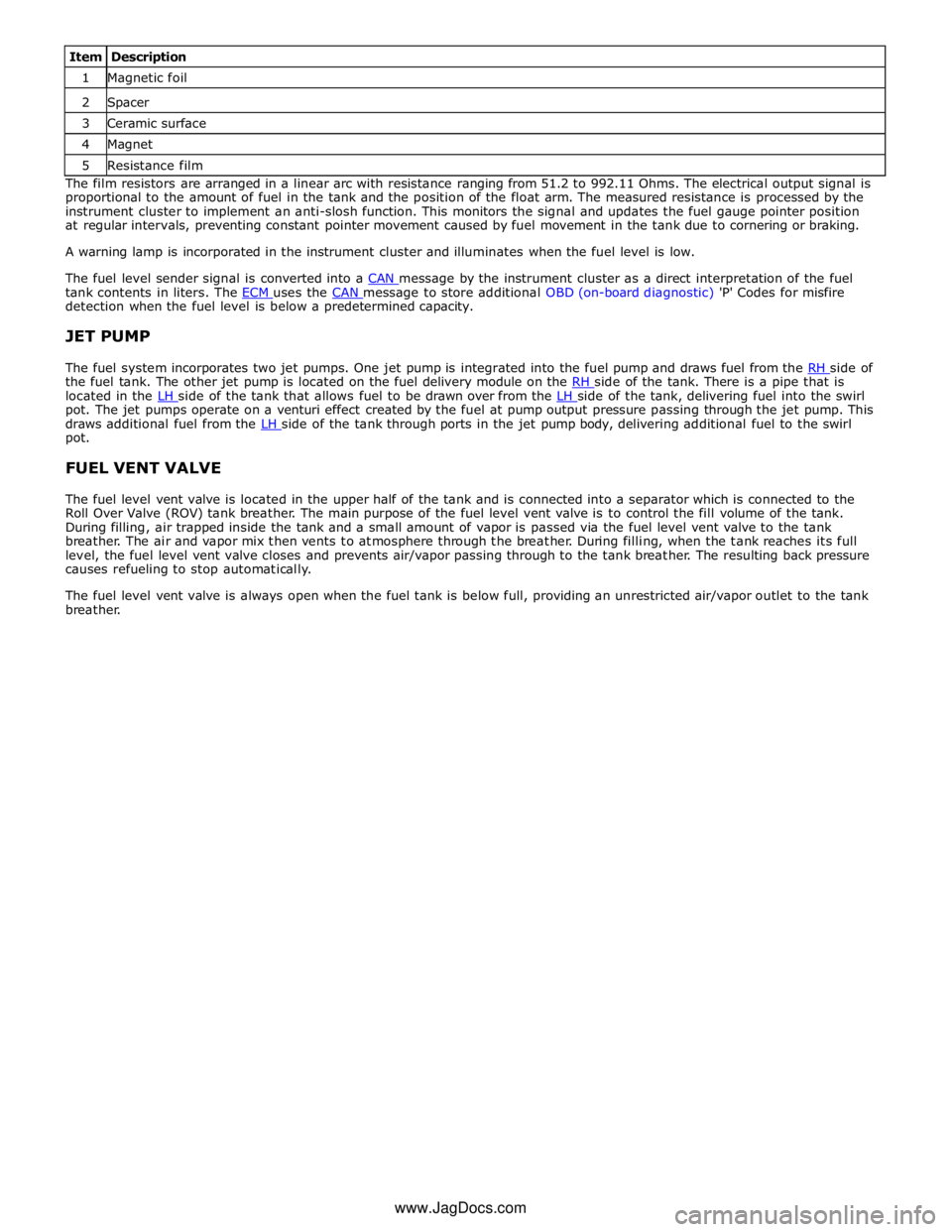
1 Magnetic foil 2 Spacer 3 Ceramic surface 4 Magnet 5 Resistance film The film resistors are arranged in a linear arc with resistance ranging from 51.2 to 992.11 Ohms. The electrical output signal is
proportional to the amount of fuel in the tank and the position of the float arm. The measured resistance is processed by the
instrument cluster to implement an anti-slosh function. This monitors the signal and updates the fuel gauge pointer position
at regular intervals, preventing constant pointer movement caused by fuel movement in the tank due to cornering or braking.
A warning lamp is incorporated in the instrument cluster and illuminates when the fuel level is low.
The fuel level sender signal is converted into a CAN message by the instrument cluster as a direct interpretation of the fuel tank contents in liters. The ECM uses the CAN message to store additional OBD (on-board diagnostic) 'P' Codes for misfire detection when the fuel level is below a predetermined capacity.
JET PUMP
The fuel system incorporates two jet pumps. One jet pump is integrated into the fuel pump and draws fuel from the RH side of the fuel tank. The other jet pump is located on the fuel delivery module on the RH side of the tank. There is a pipe that is located in the LH side of the tank that allows fuel to be drawn over from the LH side of the tank, delivering fuel into the swirl pot. The jet pumps operate on a venturi effect created by the fuel at pump output pressure passing through the jet pump. This
draws additional fuel from the LH side of the tank through ports in the jet pump body, delivering additional fuel to the swirl pot.
FUEL VENT VALVE
The fuel level vent valve is located in the upper half of the tank and is connected into a separator which is connected to the
Roll Over Valve (ROV) tank breather. The main purpose of the fuel level vent valve is to control the fill volume of the tank.
During filling, air trapped inside the tank and a small amount of vapor is passed via the fuel level vent valve to the tank
breather. The air and vapor mix then vents to atmosphere through the breather. During filling, when the tank reaches its full
level, the fuel level vent valve closes and prevents air/vapor passing through to the tank breather. The resulting back pressure
causes refueling to stop automatically.
The fuel level vent valve is always open when the fuel tank is below full, providing an unrestricted air/vapor outlet to the tank
breather.
www.JagDocs.com
Page 1592 of 3039
1 Wide bore filler neck 2 Fuel cap 3 Fuel cap lanyard 4 Fuel filler pipe 5 Fuel filler hose 6 Hose connection with fuel tank inlet check valve FUEL FILLER PIPE
Fuel Filler Pipe (ROW)
Page 1593 of 3039
1 Anti-trickle valve assembly 2 Wide bore filler neck 3 Fuel cap 4 Fuel cap lanyard 5 DMTL breather hose 6 DMTL breather filter 7 Fuel filler pipe 8 Connection of leak pipe to tank vapor line 9 Connection to charcoal canister 10 DMTL vapor leak pipe 11 Fuel filler hose 12 Hose connection with fuel tank inlet check valve The fuel filler head is positioned at the rear of the vehicle, above the right hand rear wheel. The filler head is covered by a
molded plastic cover which is electrically locked when the vehicle is locked. The filler cap is a conventional screw in type which
is secured to the vehicle with a lanyard. Fuel Filler Pipe (NAS)