2010 JAGUAR XFR battery location
[x] Cancel search: battery locationPage 445 of 3039

The TPMS uses active tire pressure sensors which are located on each wheel, inside the tire cavity. The sensor incorporates the
tire valve and is secured in the wheel by a nut on the outside of the wheel. The sensor contains a Printed Circuit Board which
houses a PTC (positive temperature coefficient)sensor, a Piezo pressure sensor, a radio receiver and transmitter and a lithium
battery.
The tire pressure sensors use the PTC sensor and the Piezo sensor to periodically measure the pressure and temperature of
the air inside the tire. The data is transmitted by RF data signals at either 315 MHz or 433 MHz dependant on market
requirements.
The RF transmission from the sensor contains a unique identification code in its transmission data. This allows the TPMS to
identify the wheel on the vehicle. If the sensor is replaced on a wheel, the new sensor identification will be learnt through the
learn and location process.
The tire pressure sensor can also detect when the wheel is rotating. In order to preserve battery power, the sensor uses
different transmission rates when the wheel is stationary or moving.
NOTE: For important information regarding the removal and fitting of tire pressure sensors and associated valves, see the
Tire Changing section.
Instrument Cluster Indications
Item Description 1 Low tire pressure warning indicator 2 Message center Tire Pressure Sensor
Page 827 of 3039
Published: 02-Jun-2011
Engine System - General Information - Leakage Test Using Smoke Test Equipment
General Procedures
CAUTION: The compressed air line supply pressure must be between 3.5 and 12 bar (50 and 175 psi) for the smoke test
equipment to function correctly. Do not exceed this pressure. Failure to follow this instruction may result in damage to the
smoke test equipment.
NOTES:
The vehicle battery must be in good condition and fully charged before carrying out this procedure.
On vehicles with 3.0L TDV6, it will be necessary to insert smoke at both air cleaner outlet pipes independently if the right
hand turbocharger and associated hoses are to be tested.
In some cases it may be necessary to remove undertrays, trim or engine covers to obtain access to all potential leak
locations.
Some variation in the illustrations may occur, but the essential information is always correct.
For further information regarding operation of the test equipment refer to the manufacturers operators manual supplied
with the kit.
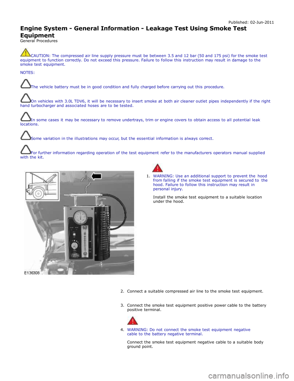
1. WARNING: Use an additional support to prevent the hood
from falling if the smoke test equipment is secured to the
hood. Failure to follow this instruction may result in
personal injury.
Install the smoke test equipment to a suitable location
under the hood.
2. Connect a suitable compressed air line to the smoke test equipment.
3. Connect the smoke test equipment positive power cable to the battery
positive terminal.
4. WARNING: Do not connect the smoke test equipment negative
cable to the battery negative terminal.
Connect the smoke test equipment negative cable to a suitable body
ground point.
Page 1266 of 3039
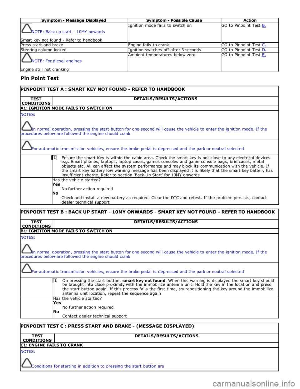
Symptom - Message Displayed Symptom - Possible Cause Action NOTE: Back up start - 10MY onwards
Smart key not found - Refer to handbook Ignition mode fails to switch on GO to Pinpoint Test B. Press start and brake Engine fails to crank GO to Pinpoint Test C. Steering column locked Ignition switches off after 3 seconds GO to Pinpoint Test D. NOTE: For diesel engines Engine still not cranking Ambient temperatures below zero GO to Pinpoint Test E.
Pin Point Test
PINPOINT TEST A : SMART KEY NOT FOUND - REFER TO HANDBOOK TEST
CONDITIONS DETAILS/RESULTS/ACTIONS A1: IGNITION MODE FAILS TO SWITCH ON NOTES:
In normal operation, pressing the start button for one second will cause the vehicle to enter the ignition mode. If the
procedures below are followed the engine should crank
For automatic transmission vehicles, ensure the brake pedal is depressed and the park or neutral selected 1 Ensure the smart Key is within the cabin area. Check the smart key is not close to any electrical devices e.g. Smart phones, laptops, laptop cases, games consoles and game console bags, briefcases, metal
objects etc. All can affect the system performance and may block its communication with the vehicle. If
the smart key battery low warning message has been displayed it is likely that the smart key battery has
insufficient charge. Refer to section 'Back Up Start' for 10MY onwards Has the vehicle started? Yes
No further action required
No
Check and install a new battery as required. Clear the DTC and retest. If the problem persists, contact
dealer technical support
PINPOINT TEST B : BACK UP START - 10MY ONWARDS - SMART KEY NOT FOUND - REFER TO HANDBOOK TEST
CONDITIONS DETAILS/RESULTS/ACTIONS B1: IGNITION MODE FAILS TO SWITCH ON NOTES:
In normal operation, pressing the start button for one second will cause the vehicle to enter the ignition mode. If the
procedures below are followed the engine should crank
For automatic transmission vehicles, ensure the brake pedal is depressed and the park or neutral selected 1 On pressing the start button, smart key not found. When this warning is displayed the smart key should be brought into close proximity with the immobilize antenna unit. Hold the key in the location and press
the start button again. If this process fails the first time, try repositioning the key around the immobilize
antenna unit location, repeat the sequence again Has the vehicle started? Yes
No further action required
No
Contact dealer technical support
PINPOINT TEST C : PRESS START AND BRAKE - (MESSAGE DISPLAYED) TEST
CONDITIONS DETAILS/RESULTS/ACTIONS C1: ENGINE FAILS TO CRANK NOTES:
Conditions for starting in addition to pressing the start button are
Page 1824 of 3039
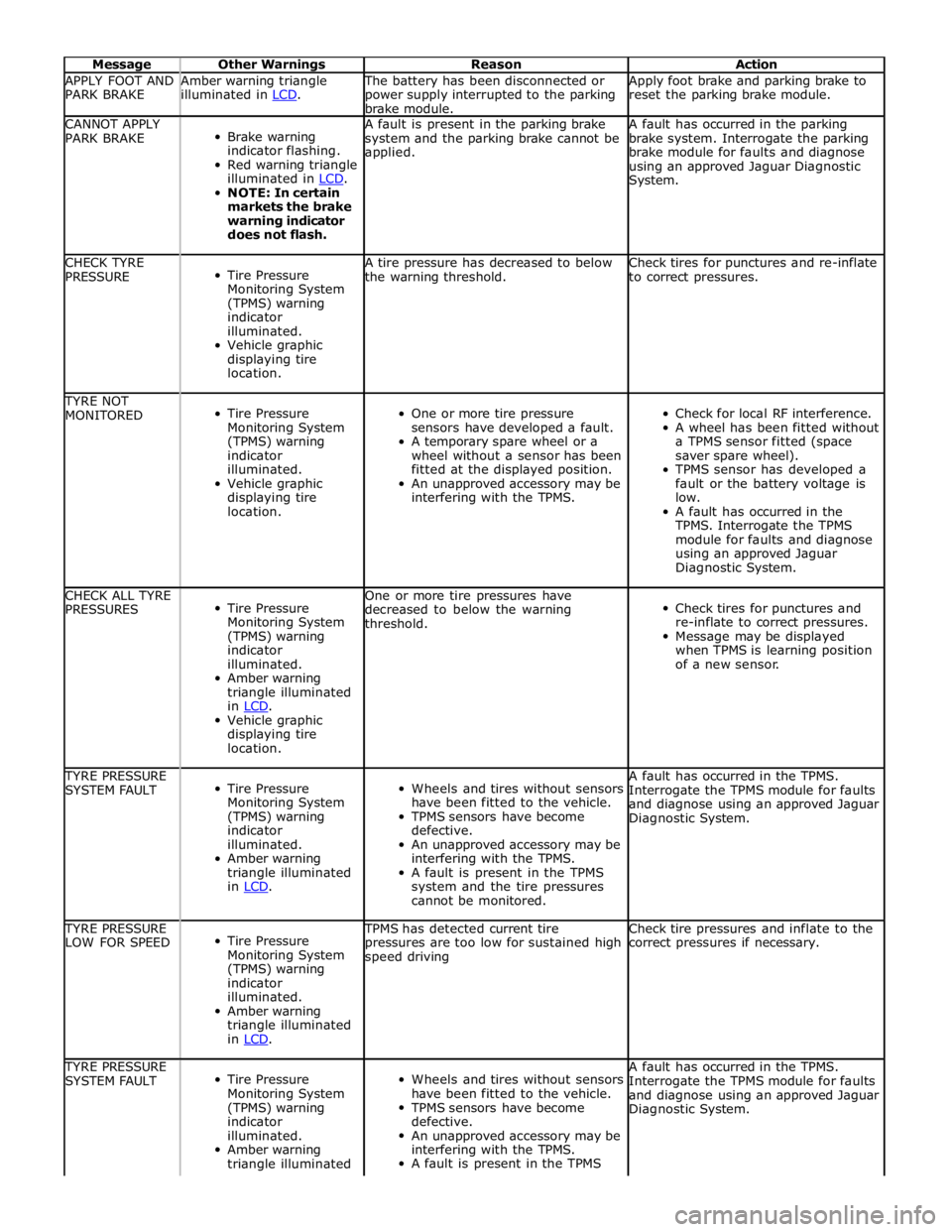
Message Other Warnings Reason Action APPLY FOOT AND
PARK BRAKE Amber warning triangle
illuminated in LCD. The battery has been disconnected or
power supply interrupted to the parking
brake module. Apply foot brake and parking brake to
reset the parking brake module. CANNOT APPLY
PARK BRAKE
Brake warning
indicator flashing.
Red warning triangle
illuminated in LCD. NOTE: In certain
markets the brake
warning indicator
does not flash. A fault is present in the parking brake
system and the parking brake cannot be
applied. A fault has occurred in the parking
brake system. Interrogate the parking
brake module for faults and diagnose
using an approved Jaguar Diagnostic
System. CHECK TYRE
PRESSURE
Tire Pressure
Monitoring System
(TPMS) warning
indicator
illuminated.
Vehicle graphic
displaying tire
location. A tire pressure has decreased to below
the warning threshold. Check tires for punctures and re-inflate
to correct pressures. TYRE NOT
MONITORED
Tire Pressure
Monitoring System
(TPMS) warning
indicator
illuminated.
Vehicle graphic
displaying tire
location.
One or more tire pressure
sensors have developed a fault.
A temporary spare wheel or a
wheel without a sensor has been
fitted at the displayed position.
An unapproved accessory may be
interfering with the TPMS.
Check for local RF interference.
A wheel has been fitted without
a TPMS sensor fitted (space
saver spare wheel).
TPMS sensor has developed a
fault or the battery voltage is
low.
A fault has occurred in the
TPMS. Interrogate the TPMS
module for faults and diagnose
using an approved Jaguar
Diagnostic System. CHECK ALL TYRE
PRESSURES
Tire Pressure
Monitoring System
(TPMS) warning
indicator
illuminated.
Amber warning
triangle illuminated
in LCD. Vehicle graphic
displaying tire
location. One or more tire pressures have
decreased to below the warning
threshold.
Check tires for punctures and
re-inflate to correct pressures.
Message may be displayed
when TPMS is learning position
of a new sensor. TYRE PRESSURE
SYSTEM FAULT
Tire Pressure
Monitoring System
(TPMS) warning
indicator
illuminated.
Amber warning
triangle illuminated
in LCD.
Wheels and tires without sensors
have been fitted to the vehicle.
TPMS sensors have become
defective.
An unapproved accessory may be
interfering with the TPMS.
A fault is present in the TPMS
system and the tire pressures
cannot be monitored. A fault has occurred in the TPMS.
Interrogate the TPMS module for faults
and diagnose using an approved Jaguar
Diagnostic System. TYRE PRESSURE
LOW FOR SPEED
Tire Pressure
Monitoring System
(TPMS) warning
indicator
illuminated.
Amber warning
triangle illuminated
in LCD. TPMS has detected current tire
pressures are too low for sustained high
speed driving Check tire pressures and inflate to the
correct pressures if necessary. TYRE PRESSURE
SYSTEM FAULT
Tire Pressure
Monitoring System
(TPMS) warning
indicator
illuminated.
Amber warning
triangle illuminated
Wheels and tires without sensors
have been fitted to the vehicle.
TPMS sensors have become
defective.
An unapproved accessory may be
interfering with the TPMS.
A fault is present in the TPMS A fault has occurred in the TPMS.
Interrogate the TPMS module for faults
and diagnose using an approved Jaguar
Diagnostic System.
Page 1827 of 3039
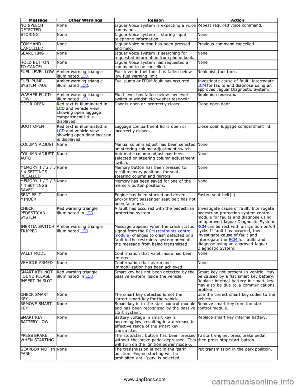
NO SPEECH
DETECTED None
Jaguar Voice system is expecting a voice
command . Repeat required voice command. STORING None
Jaguar Voice system is storing input telephone information. None COMMAND
CANCELLED None
Jaguar Voice button has been pressed
and held. Previous command cancelled. SEARCHING None
Jaguar Voice system is searching for requested information from phone book. None HOLD BUTTON TO CANCEL None
Jaguar Voice system has requested a
command to be cancelled. None FUEL LEVEL LOW
Amber warning triangle
illuminated LCD. Fuel level in fuel tank has fallen below
low fuel warning limit. Replenish fuel tank. FUEL PUMP
SYSTEM FAULT Amber warning triangle
illuminated LCD. Fuel pump or FPDM fault has occurred.
Investigate cause of fault. Interrogate
ECM for faults and diagnose using an approved Jaguar Diagnostic System. WASHER FLUID
LOW Amber warning triangle
illuminated LCD. Fluid level has fallen below low level
switch in windshield washer reservoir. Replenish reservoir. DOOR OPEN
Red text is illuminated in
LCD and vehicle view Door is open or incorrectly closed. Close open door. showing open luggage
compartment lid is
displayed. BOOT OPEN
Red text is illuminated in
LCD and vehicle view Luggage compartment lid is open or incorrectly closed. Close open luggage compartment lid. showing open door location
is displayed. COLUMN ADJUST None
Manual column adjust has been selected
on steering column adjustment switch. None COLUMN ADJUST
AUTO None
Automatic column adjust has been
selected on steering column adjustment
switch. None MEMORY 1 / 2 / 3 / 4 SETTINGS
RECALLED None
Memory button has been pressed to
recall memory positions for seat, steering column and mirrors. None MEMORY 1 / 2 / 3 / 4 SETTINGS
SAVED None
Memory has been saved for one of the
memory button positions. None SEAT BELT
MINDER None
Engine has been started and driver
and/or front passenger seat belt has not
been fastened. Fasten seat belt(s). CHECK
PEDESTRIAN
SYSTEM Red warning triangle
illuminated in LCD. A fault has occurred with the pedestrian
protection system. Investigate cause of fault. Interrogate
pedestrian protection system control
module for faults and diagnose using
an approved Jaguar Diagnostic System. INERTIA SWITCH TRIPPED Amber warning triangle
illuminated LCD. Message appears when the crash status
signal from the RCM (restraints control
module) changes to crash detected or a
fault in the restraints system prevents
the message from being transmitted. RCM can be rest with an ignition on/off cycle. If fault has occurred, then
investigate cause of fault and
interrogate the RCM for faults and diagnose using an approved Jaguar
Diagnostic System. VALET MODE None
Confirmation that valet mode has been
entered. None VEHICLE ARMED None
Confirmation that alarm and
immobilization has been achieved. None SMART KEY NOT
FOUND PLEASE
INSERT IN SLOT Red warning triangle
illuminated in LCD. Smart key has not been detected by the
passive system inside the vehicle. Smart key not present in vehicle. May
be caused by a flat smart key battery.
Replace internal battery in smart key.
May also be due to a communications problem. CHECK SMART
KEY None The smart key detected is not the
correct smart key for the vehicle. Use the correct smart key coded to the
vehicle. REMOVE SMART
KEY None
Smart key is in the start control module
and has been recognized by the passive
start system. Remove smart key from the start
control module. SMART KEY
BATTERY LOW None
Battery voltage in smart key is
becoming low, resulting in a decrease in
effective range of the smart key
transmitter. Replace smart key internal battery. PRESS BRAKE
WHEN STARTING None The stop/start button has been pressed
without the brake pedal depressed. This
will turn on the ignition power mode 6. To start engine, press brake pedal,
then press stop/start button. GEARBOX NOT IN
PARK None The transmission is not in the 'park'
position. Engine starting will be prohibited until 'park' is selected. Put transmission in the park position. www.JagDocs.com
Page 1828 of 3039
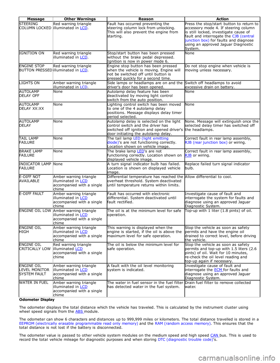
STEERING
COLUMN LOCKED Red warning triangle
illuminated in LCD. Fault has occurred preventing the
steering column lock from unlocking. This will also prevent the engine from
starting. Press the stop/start button to return to
accessory mode 4. If steering column
is still locked, investigate cause of
fault and interrogate the CJB (central junction box) for faults and diagnose
using an approved Jaguar Diagnostic System. IGNITION ON
Red warning triangle
illuminated in LCD. Stop/start button has been pressed
without the brake pedal depressed. Ignition is now in power mode 6. None ENGINE STOP
BUTTON PRESSED Red warning triangle
illuminated in LCD. Engine stop button has been pressed
when the vehicle is moving. Engine will
not be switched off until button is pressed quickly for a second time. Do not stop engine when vehicle is
moving unless necessary. LIGHTS ON
Amber warning triangle
illuminated in LCD. Side lamps or headlamps are on and the
driver's door has been opened. Switch off headlamps to avoid
excessive drain on battery. AUTOLAMP
DELAY OFF None
Autolamp delay feature has been
deactivated by moving light control
switch from the auto position. None AUTOLAMP
DELAY XX:XX None
Lighting control switch has been moved
to one of the 4 autolamp delay
positions. Message displays delay timer period selected. None AUTOLAMP
DELAY None
Autolamp delay is selected on the light
control switch and the driver has
switched off ignition and opened driver's
door initiating the autolamp delay. None. Message will extinguish once the
selected delay timer has switched off
the headlamps. TAIL LAMP
FAILURE None The tail lamp LED (light emitting
diode)'s are not functioning correctly.
Location shown on vehicle image. Correct fault in rear lamp assembly,
RJB (rear junction box) or wiring. BRAKE LAMP
FAILURE None The brake lamp LED's are not functioning correctly. Location shown on displayed vehicle image. Correct fault in rear lamp assembly,
RJB or wiring. INDICATOR LAMP
FAILURE None
A turn signal indicator bulb has failed.
Location is shown on displayed vehicle image. Replace failed turn signal indicator
bulb. E-DIFF NOT
AVAILABLE Amber warning triangle
illuminated in LCD accompanied with a single
chime Differential temperature has reached the
overheat threshold. System deactivated
until temperature returns within limits. Allow differential to cool. E-DIFF FAULT
Amber warning triangle
illuminated in LCD accompanied with a single
chime Fault has occurred with electronic
differential. System deactivated until
fault rectified. Investigate cause of fault and
interrogate the system for faults and
diagnose using an approved Jaguar Diagnostic System. ENGINE OIL LOW
Amber warning triangle
illuminated in LCD accompanied with a single
chime The oil is at the minimum level for safe
operation. Top-up with 1 liter (1.8 pints) of oil. ENGINE OIL
HIGH Amber warning triangle
illuminated in LCD accompanied with a single
chime This warning is displayed when the
engine is started, if the oil is above the
maximum level for safe operation. Stop the vehicle as soon as safety
permits and have the engine oil
drained to correct level, before driving
the vehicle. ENGINE OIL
CRITICALLY LOW Red warning triangle
illuminated LCD accompanied with a single
chime The oil is below the minimum level for
safe operation. Stop the vehicle as soon as safety
permits and top-up with 1.5 liters (2.6
pints) of oil. Wait for 10 minutes,
re-check the oil level reading and top-up again if necessary. ENGINE OIL
LEVEL MONITOR
SYSTEM FAULT Amber warning triangle
illuminated in LCD accompanied with a single
chime A fault with the oil level monitoring
system is indicated. Investigate cause of fault and
interrogate the ECM for faults and diagnose using an approved Jaguar Diagnostic System. WATER IN FUEL
Amber warning triangle
illuminated in LCD accompanied with a single
chime The water in fuel sensor in the fuel filter
has detected water in the fuel system. Drain fuel filter to remove collected
water. Odometer Display
The odometer displays the total distance which the vehicle has traveled. This is calculated by the instrument cluster using
wheel speed signals from the ABS module.
The odometer can show 6 characters and distances up to 999,999 miles or kilometers. The total distance travelled is stored in a
EEPROM (electrically erasable programmable read only memory) and the RAM (random access memory). This ensures that the
total distance is not lost if the battery is disconnected.
The odometer value is passed to other vehicle system modules on the medium speed and high speed CAN bus. This is used to record the total vehicle mileage for diagnostic purposes and when storing DTC (diagnostic trouble code)'s.
Page 1867 of 3039
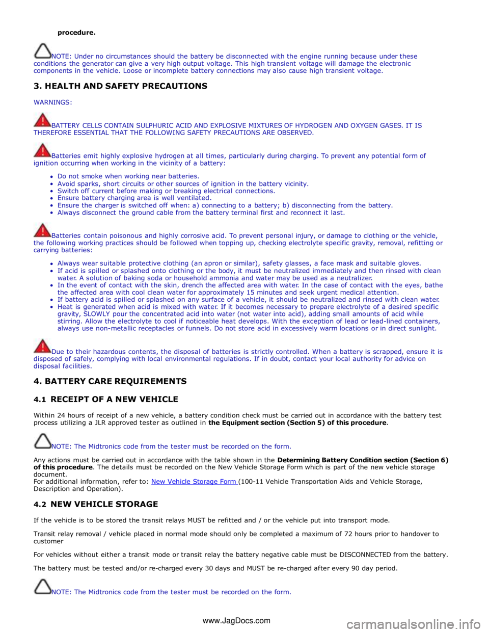
procedure.
NOTE: Under no circumstances should the battery be disconnected with the engine running because under these
conditions the generator can give a very high output voltage. This high transient voltage will damage the electronic
components in the vehicle. Loose or incomplete battery connections may also cause high transient voltage.
3. HEALTH AND SAFETY PRECAUTIONS
WARNINGS:
BATTERY CELLS CONTAIN SULPHURIC ACID AND EXPLOSIVE MIXTURES OF HYDROGEN AND OXYGEN GASES. IT IS
THEREFORE ESSENTIAL THAT THE FOLLOWING SAFETY PRECAUTIONS ARE OBSERVED.
Batteries emit highly explosive hydrogen at all times, particularly during charging. To prevent any potential form of
ignition occurring when working in the vicinity of a battery:
Do not smoke when working near batteries.
Avoid sparks, short circuits or other sources of ignition in the battery vicinity.
Switch off current before making or breaking electrical connections.
Ensure battery charging area is well ventilated.
Ensure the charger is switched off when: a) connecting to a battery; b) disconnecting from the battery.
Always disconnect the ground cable from the battery terminal first and reconnect it last.
Batteries contain poisonous and highly corrosive acid. To prevent personal injury, or damage to clothing or the vehicle,
the following working practices should be followed when topping up, checking electrolyte specific gravity, removal, refitting or
carrying batteries:
Always wear suitable protective clothing (an apron or similar), safety glasses, a face mask and suitable gloves.
If acid is spilled or splashed onto clothing or the body, it must be neutralized immediately and then rinsed with clean
water. A solution of baking soda or household ammonia and water may be used as a neutralizer.
In the event of contact with the skin, drench the affected area with water. In the case of contact with the eyes, bathe
the affected area with cool clean water for approximately 15 minutes and seek urgent medical attention.
If battery acid is spilled or splashed on any surface of a vehicle, it should be neutralized and rinsed with clean water.
Heat is generated when acid is mixed with water. If it becomes necessary to prepare electrolyte of a desired specific
gravity, SLOWLY pour the concentrated acid into water (not water into acid), adding small amounts of acid while
stirring. Allow the electrolyte to cool if noticeable heat develops. With the exception of lead or lead-lined containers,
always use non-metallic receptacles or funnels. Do not store acid in excessively warm locations or in direct sunlight.
Due to their hazardous contents, the disposal of batteries is strictly controlled. When a battery is scrapped, ensure it is
disposed of safely, complying with local environmental regulations. If in doubt, contact your local authority for advice on
disposal facilities.
4. BATTERY CARE REQUIREMENTS
4.1 RECEIPT OF A NEW VEHICLE
Within 24 hours of receipt of a new vehicle, a battery condition check must be carried out in accordance with the battery test
process utilizing a JLR approved tester as outlined in the Equipment section (Section 5) of this procedure.
NOTE: The Midtronics code from the tester must be recorded on the form.
Any actions must be carried out in accordance with the table shown in the Determining Battery Condition section (Section 6)
of this procedure. The details must be recorded on the New Vehicle Storage Form which is part of the new vehicle storage
document.
For additional information, refer to: New Vehicle Storage Form (100-11 Vehicle Transportation Aids and Vehicle Storage, Description and Operation).
4.2 NEW VEHICLE STORAGE
If the vehicle is to be stored the transit relays MUST be refitted and / or the vehicle put into transport mode.
Transit relay removal / vehicle placed in normal mode should only be completed a maximum of 72 hours prior to handover to
customer
For vehicles without either a transit mode or transit relay the battery negative cable must be DISCONNECTED from the battery.
The battery must be tested and/or re-charged every 30 days and MUST be re-charged after every 90 day period.
NOTE: The Midtronics code from the tester must be recorded on the form. www.JagDocs.com
Page 1877 of 3039
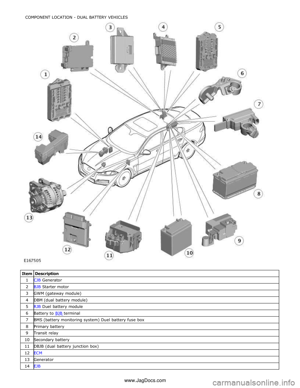
1 CJB Generator 2 BJB Starter motor 3 GWM (gateway module) 4 DBM (dual battery module) 5 RJB Duel battery module 6 Battery to BJB terminal 7 BMS (battery monitoring system) Duel battery fuse box 8 Primary battery 9 Transit relay 10 Secondary battery 11 DBJB (dual battery junction box) 12 ECM 13 Generator 14 EJB COMPONENT LOCATION - DUAL BATTERY VEHICLES
www.JagDocs.com