2010 JAGUAR XFR battery location
[x] Cancel search: battery locationPage 1893 of 3039

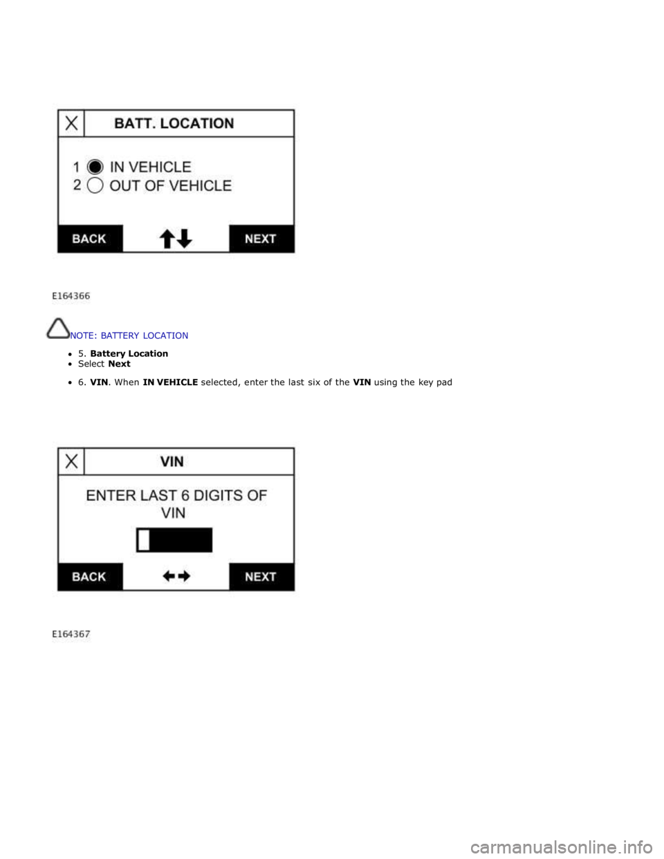
NOTE: BATTERY LOCATION
5. Battery Location
Select Next
6. VIN. When IN VEHICLE selected, enter the last six of the VIN using the key pad
Page 2076 of 3039

CAN Harness Architecture
For a detailed description of the CAN Networks and architecture, refer to the relevant Description and Operation section in the
Workshop Manual.
CAN Network Integrity Tests
If a control module is suspected of non-communication, the Network Integrity test application available on the manufacturer
approved diagnostic system can be used to confirm if communication is possible between the control modules on the vehicle
and the manufacturer approved diagnostic system (via the J1962 diagnostic connector ). The results from the test can be used
to determine if either a single module or multiple modules are failing to communicate.
CAN Terminating Modules
If the Network Integrity test indicates that one or more module on one of the CAN networks (HS or MS) are failing to
communicate, there are several checks that can be made. The first step is to identify if both of the CAN terminating modules
on each individual CAN Bus are communicating. If both CAN terminating modules for each individual CAN Bus are
communicating (identified via the Network Integrity test), then it can be confirmed that the main 'backbone' of the CAN
harness is complete. The main 'backbone' of the CAN harness consists of all the modules connected to the CAN harness via a
'loop' configuration and also includes the two terminating modules.
Communication with both CAN terminating modules via the Network Integrity test confirms the physical integrity of the main
'backbone' of the CAN harness (and the harness spur to the J1962 diagnostic connector). This means that there is no
requirement to check the resistance of the CAN Network. This is because the standard check for 60 ohms across the CAN High
and CAN Low lines will not provide any additional information regarding the physical condition of the CAN harness, beyond
what has already been determined from the Network Integrity test.
Non-Communication of a Terminating Module
If a Network Integrity test reveals a terminating module is failing to communicate it can indicate a break in the main
'backbone' of the CAN harness. The first checks should always be to confirm the power and ground supplies to the
non-communicating module are correct. Providing these are correct, the resistance between the CAN High and CAN Low lines at
the J1962 connector can be checked to determine the integrity of the main 'backbone' of the CAN harness. After disconnecting
the battery a reading of 120 ohms would indicate an open circuit in the main 'backbone' of the CAN harness. Alternatively, a
reading of 60 ohms would indicate that there is no open circuit fault with the main 'backbone' of the CAN harness.
It is worth noting that even if one of the terminating modules is disconnected from the CAN harness, communications between
the modules still connected may still be possible. Therefore communication between the manufacturer approved diagnostic
system and the connected modules may also be possible.
Locating CAN Harness Open Circuits
In the case where multiple modules, including a terminating module, are failing to communicate, having first confirmed the
power and ground supplies are correct, the approximate location of the open circuit can be identified from analysis of the
Network Integrity test results and reference to the relevant CAN network circuit diagrams. For example, if an open circuit
existed in a certain position on the CAN harness, any module positioned on the Network between the J1962 connector and the
open circuit should return a response during the Network Integrity test. No responses would be returned from any modules
past the open circuit fault in the Network.
CAN Harness 'Spur' Type Configuration Circuits
If, after the initial checks (Network Integrity test using the manufacturer approved diagnostic system, and power and ground
supplies to the module have been checked and confirmed as correct), a module that is connected to the CAN harness via a
'spur' type configuration is suspected of not communicating, then the physical integrity of the CAN harness 'spur' can be
checked.
This is most easily undertaken by individually checking the continuity of the CAN High and CAN Low lines between the
non-communicating module connector (with the module disconnected) and the J1962 diagnostic connector.
'Lost Communications' DTCs
As well as the methods described so far in this document, which can be used to determine the location of an open circuit in
the CAN harness, 'Lost Communications' DTCs can also be used for this purpose. Lost communication DTCs mean that a
module is not receiving CAN information from another module.
For example, if a global DTC read were to be carried out, only DTCs stored in the modules that the manufacturer approved
diagnostic system could communicate with would be displayed. If there was an open circuit fault in a certain position on the
CAN harness, the modules that could display DTCs would all be prior to the open circuit on the Network, and these modules
should display 'Lost Communications' DTCs with all the modules located on the Network past the open circuit fault.
'Bus off' DTCs
The references to bus and its condition refer to the network concerned and the modules on that network.
If a module logs a 'Bus Off' DTC, it means that the module has detected CAN transmission errors and has disabled it's own
CAN transmissions and disconnected itself from the network in an attempt to allow the rest of the network to function. At this
point the 'Bus Off' DTC is set. A common cause of 'Bus Off' DTCs can be a short circuit in the CAN network.
Page 2172 of 3039

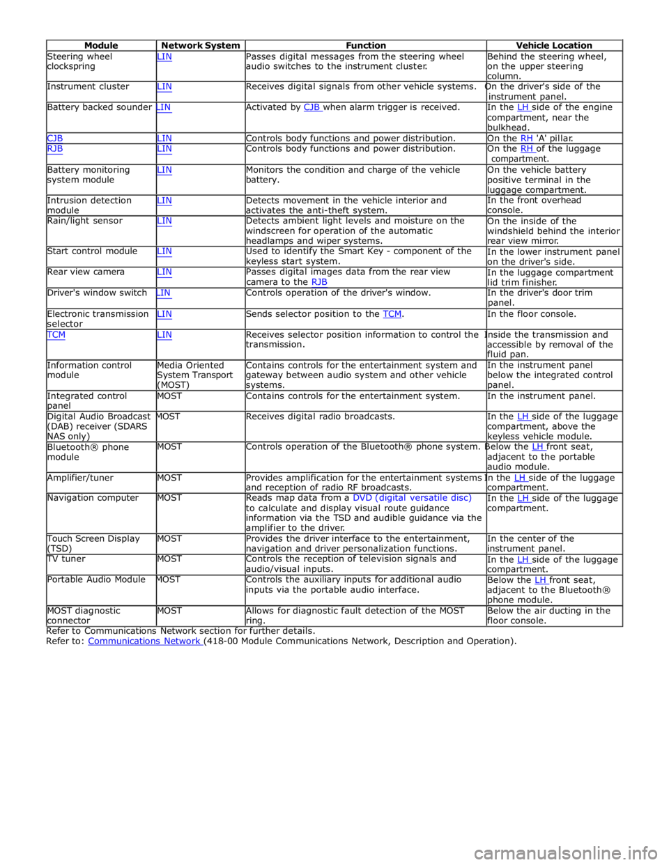
Module Network System Function Vehicle Location
Steering wheel
clockspring LIN Passes digital messages from the steering wheel
audio switches to the instrument cluster. Behind the steering wheel,
on the upper steering
column.
Instrument cluster LIN Receives digital signals from other vehicle systems. On the driver's side of the
instrument panel.
Battery backed sounder LIN Activated by CJB when alarm trigger is received. In the LH side of the engine compartment, near the
bulkhead.
CJB LIN Controls body functions and power distribution. On the RH 'A' pillar.
RJB LIN Controls body functions and power distribution. On the RH of the luggage compartment.
Battery monitoring
system module
Intrusion detection
module LIN Monitors the condition and charge of the vehicle
battery.
LIN Detects movement in the vehicle interior and
activates the anti-theft system. On the vehicle battery
positive terminal in the
luggage compartment.
In the front overhead
console.
Rain/light sensor LIN Detects ambient light levels and moisture on the
windscreen for operation of the automatic
headlamps and wiper systems.
Start control module LIN Used to identify the Smart Key - component of the
keyless start system.
Rear view camera LIN Passes digital images data from the rear view
camera to the RJB On the inside of the
windshield behind the interior
rear view mirror.
In the lower instrument panel
on the driver's side.
In the luggage compartment
lid trim finisher.
Driver's window switch LIN Controls operation of the driver's window. In the driver's door trim
panel.
Electronic transmission
selector LIN Sends selector position to the TCM. In the floor console. TCM LIN Receives selector position information to control the Inside the transmission and
Information control
module
Media Oriented
System Transport
(MOST) transmission.
Contains controls for the entertainment system and
gateway between audio system and other vehicle
systems. accessible by removal of the
fluid pan.
In the instrument panel
below the integrated control
panel.
Integrated control
panel MOST Contains controls for the entertainment system. In the instrument panel.
Digital Audio Broadcast MOST Receives digital radio broadcasts. In the LH side of the luggage (DAB) receiver (SDARS
NAS only)
Bluetooth® phone
module compartment, above the
keyless vehicle module.
MOST Controls operation of the Bluetooth® phone system. Below the LH front seat, adjacent to the portable
audio module.
Amplifier/tuner MOST Provides amplification for the entertainment systems In the LH side of the luggage and reception of radio RF broadcasts.
Navigation computer MOST Reads map data from a DVD (digital versatile disc)
to calculate and display visual route guidance
information via the TSD and audible guidance via the
amplifier to the driver. compartment.
In the LH side of the luggage compartment.
Touch Screen Display
(TSD) MOST Provides the driver interface to the entertainment,
navigation and driver personalization functions. In the center of the
instrument panel.
TV tuner MOST Controls the reception of television signals and
audio/visual inputs.
Portable Audio Module MOST Controls the auxiliary inputs for additional audio
inputs via the portable audio interface. In the LH side of the luggage compartment.
Below the LH front seat, adjacent to the Bluetooth®
phone module.
MOST diagnostic
connector MOST Allows for diagnostic fault detection of the MOST
ring. Below the air ducting in the
floor console.
Refer to Communications Network section for further details.
Refer to: Communications Network (418-00 Module Communications Network, Description and Operation).
Page 2341 of 3039

6. Locate climate seat module, (refer to Electrical Information - Electrical Reference Library, contained in TOPIx) for
guidance on how to gain access to the connector(s)
7. Locate and disconnect relevant connector prior to pin test
8. Using ohm-meter to probe each heat/cooled unit pins (at rear of connector), reading should achieve no greater than 10
ohms after 1 minute (initial fluctuations in readings may occur using ohm-meter, post 1 minute readings will have
stabilized)
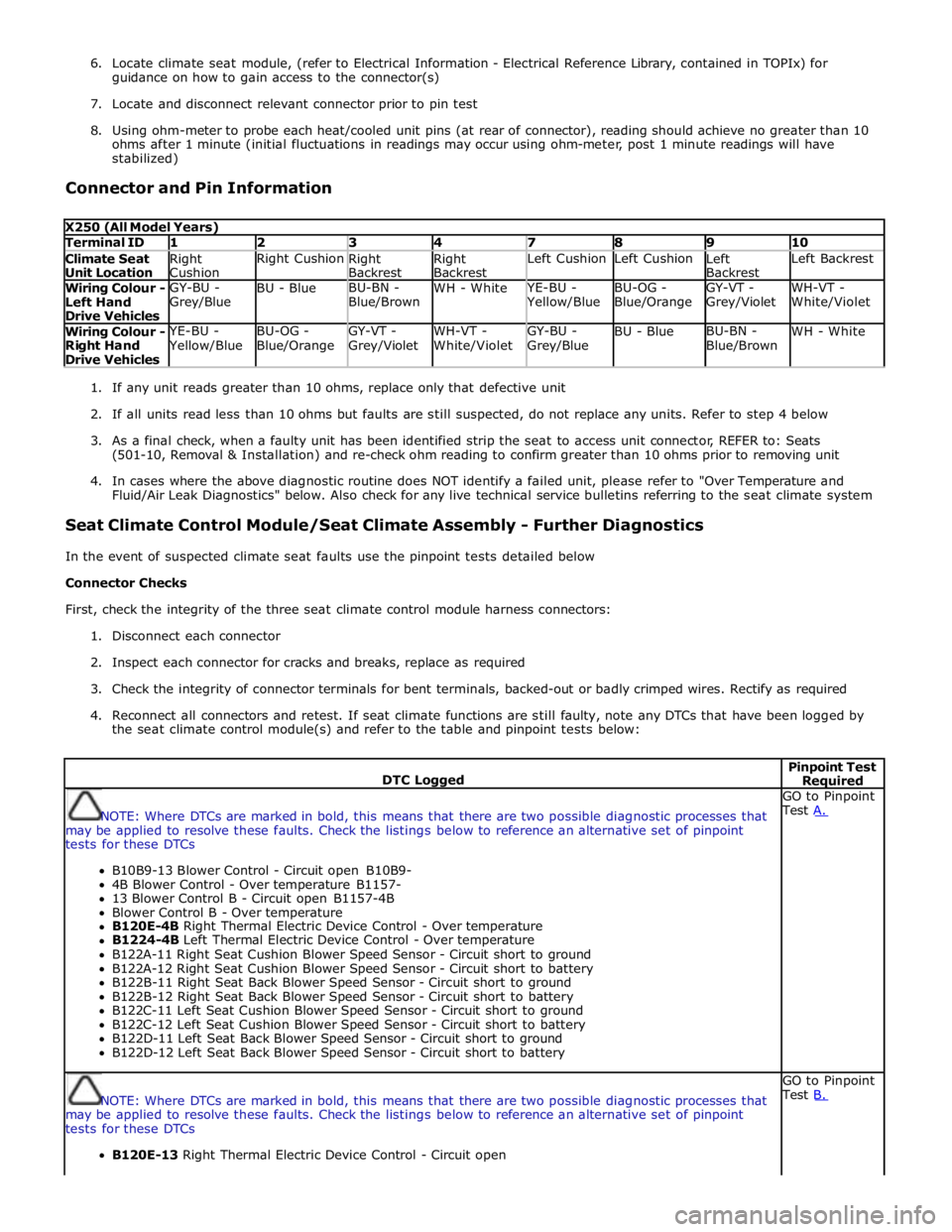
Connector and Pin Information
X250 (All Model Years) Terminal ID 1 2 3 4 7 8 9 10 Climate Seat
Unit Location Right
Cushion Right Cushion
Right
Backrest Right
Backrest Left Cushion Left Cushion
Left
Backrest Left Backrest Wiring Colour -
Left Hand
Drive Vehicles GY-BU -
Grey/Blue BU - Blue BU-BN -
Blue/Brown WH - White YE-BU - Yellow/Blue BU-OG -
Blue/Orange GY-VT -
Grey/Violet WH-VT -
White/Violet Wiring Colour -
Right Hand
Drive Vehicles YE-BU - Yellow/Blue BU-OG -
Blue/Orange GY-VT -
Grey/Violet WH-VT -
White/Violet GY-BU -
Grey/Blue BU - Blue BU-BN -
Blue/Brown WH - White
1. If any unit reads greater than 10 ohms, replace only that defective unit
2. If all units read less than 10 ohms but faults are still suspected, do not replace any units. Refer to step 4 below
3. As a final check, when a faulty unit has been identified strip the seat to access unit connector, REFER to: Seats
(501-10, Removal & Installation) and re-check ohm reading to confirm greater than 10 ohms prior to removing unit
4. In cases where the above diagnostic routine does NOT identify a failed unit, please refer to "Over Temperature and
Fluid/Air Leak Diagnostics" below. Also check for any live technical service bulletins referring to the seat climate system
Seat Climate Control Module/Seat Climate Assembly - Further Diagnostics
In the event of suspected climate seat faults use the pinpoint tests detailed below
Connector Checks
First, check the integrity of the three seat climate control module harness connectors:
1. Disconnect each connector
2. Inspect each connector for cracks and breaks, replace as required
3. Check the integrity of connector terminals for bent terminals, backed-out or badly crimped wires. Rectify as required
4. Reconnect all connectors and retest. If seat climate functions are still faulty, note any DTCs that have been logged by
the seat climate control module(s) and refer to the table and pinpoint tests below:
DTC Logged Pinpoint Test Required
NOTE: Where DTCs are marked in bold, this means that there are two possible diagnostic processes that
may be applied to resolve these faults. Check the listings below to reference an alternative set of pinpoint
tests for these DTCs
B10B9-13 Blower Control - Circuit open B10B9-
4B Blower Control - Over temperature B1157-
13 Blower Control B - Circuit open B1157-4B
Blower Control B - Over temperature
B120E-4B Right Thermal Electric Device Control - Over temperature
B1224-4B Left Thermal Electric Device Control - Over temperature
B122A-11 Right Seat Cushion Blower Speed Sensor - Circuit short to ground
B122A-12 Right Seat Cushion Blower Speed Sensor - Circuit short to battery
B122B-11 Right Seat Back Blower Speed Sensor - Circuit short to ground
B122B-12 Right Seat Back Blower Speed Sensor - Circuit short to battery
B122C-11 Left Seat Cushion Blower Speed Sensor - Circuit short to ground
B122C-12 Left Seat Cushion Blower Speed Sensor - Circuit short to battery
B122D-11 Left Seat Back Blower Speed Sensor - Circuit short to ground
B122D-12 Left Seat Back Blower Speed Sensor - Circuit short to battery GO to Pinpoint
Test A.
NOTE: Where DTCs are marked in bold, this means that there are two possible diagnostic processes that
may be applied to resolve these faults. Check the listings below to reference an alternative set of pinpoint
tests for these DTCs
B120E-13 Right Thermal Electric Device Control - Circuit open GO to Pinpoint
Test B.