2010 JAGUAR XFR Throttle
[x] Cancel search: ThrottlePage 648 of 3039

7 Instrument cluster 8 Parking brake switch 9 Parking brake actuator
Static Apply System Operation
The EPB module receives a vehicle speed signal from the ABS (anti-lock brake system) module on the high speed CAN bus. If the parking brake switch is pulled to the 'Apply' position and vehicle speed is less than 2 mph (3 km/h), the EPB module will
instigate its 'Static Apply' mode and drive the actuator to apply full parking brake force to the rear wheels.
The EPB module monitors the current drawn by the actuator and compares this to information held within its configuration
software to determine when full braking force has been applied.
Dynamic Apply
There are two 'Dynamic Apply' modes; low speed dynamic and high speed dynamic. The low speed dynamic mode operates at
speeds between 2 mph (3 km/h) and 20 mph (32 km/h). The high speed dynamic mode operates at speeds above 20 mph (32
km/h).
If the parking brake switch is pulled up to the 'Apply' position and vehicle speed is within the low speed dynamic range, the
EPB module drives the actuator to apply full parking brake force to the rear wheels.
If the parking brake switch is pulled up to the 'Apply' position and vehicle speed is within the high speed dynamic range, the
EPB module will apply braking force to the rear wheels at a slower rate until full braking load is reached or the switch is
released. The rate with which braking force is applied is controlled by the EPB module, which monitors both current drawn by
the actuator and positional information from the actuator hall sensor and compares this to information held within its
configuration software.
Drive Away Release
The EPB module will initiate its 'Drive Away Release' function and automatically release the parking brake if the following
conditions are detected:
The engine is running.
Drive , or reverse is selected.
Positive throttle movement is detected.
The EPB module receives messages of gear selector position and throttle angle over the high speed CAN bus from the TCM (transmission control module) and the ECM (engine control module) respectively.
Release from Park
The EPB module will initiate its 'Release from Park' function and automatically release the parking brake if the gear selector is
moved from Park to any position except Neutral.
Repairs
Before carrying out any work on the parking brake system, the Jaguar approved diagnostic system must be connected and the
'parking brake unjam' routine run. The routine can be found in the 'Vehicle Configuration' area, under the 'Set-up and
Configuration' menu. After any work has been carried out on the parking brake, the system will require resetting.
CAUTION: Do not use the 'Emergency Release' tool to allow work to be carried out on the parking brake. Work can only be
carried out on the parking brake system after the 'parking brake unjam' routine has been run.
Resetting
If the electrical supply is disconnected from the EPB module, the actuator will loose its position memory. On battery
re-connection and ignition on, 'APPLY FOOT AND PARK BRAKE' will be displayed in the instrument cluster message center
indicating the parking brake requires resetting.
Refer to: Parking Brake (206-05, Diagnosis and Testing).
Operating Voltages
The EPB module will only operate the actuator if the power supply from the battery is between 9 V and 16 V. At any voltage
within this range, the actuator is able to fully tighten and release the brake cables. If the power supply falls outside of the
range, a fault code is stored in the EPB module and can be retrieved using the Jaguar approved diagnostic system.
Page 692 of 3039

Published: 11-May-2011
Anti-Lock Control - Stability Assist - Anti-Lock Control - Stability Assist - Overview
Description and Operation
Overview
The ABS (anti-lock brake system) and DSC (dynamic stability control) system features a Bosch modulator, which is an
integrated four-channel HCU (hydraulic control unit) and ABS module. The unit is located in the rear of the engine compartment on the passenger side, and is installed in the brake hydraulic circuit between the brake master cylinder and the four brake
calipers.
The ABS module is connected to the high speed CAN (controller area network) bus, and actively interacts with other vehicle system control modules and associated sensors to receive and transmit current vehicle operating information.
When required, the ABS module will actively intervene and operate the HCU during braking or vehicle maneuvers to correct the vehicle attitude, stability, traction or speed. During incidents of vehicle correction, the ABS module may also request the ECM (engine control module) to control engine power in order to further stabilize and correct the vehicle.
To provide full system functionality, the ABS and DSC system comprise the following components: DSC switch.
Four wheel speed sensors.
Steering angle sensor.
Yaw rate and lateral acceleration sensor.
Stoplamp switch.
Instrument cluster indicator lamps.
Integrated ABS module and HCU. Brake booster vacuum sensor (3.0L vehicles only).
Two variants of ABS module are available, Bosch ESP®8.1 and Bosch ESP®plus8.1. The Bosch ESP®plus8.1 system is fitted to vehicles with ACC (adaptive cruise control) and incorporates a new feature to Jaguar known as 'electronic brake prefill'.
Electronic brake prefill, senses any rapid throttle lift off, activating a small brake hydraulic pressure build-up of approximately 3
to 5 bar (43.5 to 72.5 lbf/in²) in anticipation of the brakes being applied. This application produces a quicker brake pedal
response and consequently slightly shorter stopping distances. When the ECM detects rapid throttle lift off it signals the ABS module which controls the HCU to apply a low brake pressure to assist in a quicker brake application.
NOTE: All vehicles with ACC are supported by the Bosch ESP®plus8.1 system.
The ABS provides the following brake functions that are designed to assist the vehicle or aid the driver: ABS. DSC, including Trac DSC.
CBC (corner brake control).
EBD (electronic brake force distribution).
ETC (electronic traction control).
EBA (emergency brake assist).
EDC (engine drag-torque control).
Understeer control.
Electronic brake prefill (vehicles with ACC only).
Brake vacuum assist (3.0L vehicles only).
All the brake functions listed are automatically active when the ignition is in power mode and the engine is running. The DSC
system can be selected to off using the DSC switch.
WARNING: Although the vehicle is fitted with DSC, it remains the drivers responsibility to drive safely according to the
prevailing conditions.
Page 696 of 3039

a decrease in engine torque. At the same time the ABS module will control the HCU to apply brake pressure to the relevant wheels to correct the understeer.
Electronic Brake Prefill (Vehicles With ACC Only)
Electronic brake prefill (Bosch ESP®plus8.1), senses any rapid throttle lift off, activating a small brake hydraulic pressure
build-up of approximately 3 to 5 bar (43.5 to 72.5 lbf/in²) in anticipation of the brakes being applied.
This application produces a quicker brake pedal response and consequently slightly shorter stopping distances. The system
supports vehicles with ACC (adaptive cruise control).
When the ABS module detects rapid throttle lift off (from the signals received from the ECM over the high speed CAN bus), it controls the HCU to apply a low brake pressure to assist in a quicker brake application.
Brake Vacuum Assist (3.0L Vehicles Only)
Operation of Brake Vacuum Assist generally occurs at the beginning of an ignition cycle when brake booster vacuum levels are
low; refer to Brake Booster Vacuum sensor, below.
Brake vacuum assist operation will be recognized by the driver experiencing a vibrating brake pedal and slight modulator noise.
This will be similar to that experienced when ABS system is operating.
As the engine warms up, Brake Vacuum Assist operation will become less frequent. However, it can be become more active
when vacuum levels are low due to driving at high-altitudes, or during frequent heavy-braking.
Noise levels during Brake Vacuum Assist may vary with initial system activity being the loudest observed. In some
circumstances initial activity may be interpreted as a 'thump' noise, particularly if there is no immediate and significant Brake
Vacuum Assist functionality.
In this circumstance system behavior is normal and should not be a cause for fault investigation.
Dynamic Stability Control Switch Component Description
Item Description 1 DSC switch The DSC switch is mounted in the floor console adjacent to the JaguarDrive selector.
Page 816 of 3039

9. WEAK VALVE SPRINGS: When the needle oscillation becomes more violent as engine RPM is increased, weak valve
springs are indicated. The reading at idle could be relatively steady.
10. LATE VALVE TIMING: A steady but low reading could be caused by late valve timing.
11.
IGNITION TIMING RETARDED: Retarded ignition timing will produce a steady but somewhat low reading.
12.
INSUFFICIENT SPARK PLUG GAP: When spark plugs are gapped too close, a regular, small pulsation of the needle can
occur.
13. INTAKE LEAK: A low, steady reading can be caused by an intake manifold or throttle body gasket leak.
14.
BLOWN HEAD GASKET: A regular drop of fair magnitude can be caused by a blown head gasket or warped cylinder head
to cylinder block surface.
15.
RESTRICTED EXHAUST SYSTEM: When the engine is first started and is idled, the reading may be normal, but as the
engine RPM is increased, the back pressure caused by a clogged muffler, kinked tail pipe or other concerns will cause
the needle to slowly drop to 0 kPa (0 in-Hg). The needle then may slowly rise. Excessive exhaust clogging will cause
the needle to drop to a low point even if the engine is only idling.
When vacuum leaks are indicated, search out and correct the cause. Excess air leaking into the system will upset the fuel
mixture and cause concerns such as rough idle, missing on acceleration or burned valves. If the leak exists in an accessory
such as the power brake booster, the unit will not function correctly. Always repair vacuum leaks.
Engine Oil Pressure Check
NOTE: Prior to checking the engine oil pressure, a road test of 6 miles (10 kilometres), must be carried out. Do not
attempt to attain engine normal operating temperature by allowing the engine to idle.
1. Disconnect the battery ground cable. Refer to section 414-00 - Charging System - General Information of the workshop
manual
2. WARNINGS:
The spilling of hot engine oil is unavoidable during this procedure, care must be taken to prevent scalding.
Wear protective gloves.
Remove the engine oil filter element
REFER to: Oil Filter Element (303-01C Engine - V8 5.0L Petrol, Removal and Installation).
NOTE: Ensure the oil filter element is not contaminated during this procedure
3. Install the oil filter element into special tool (Oil filter adapter number 303-1451)
4. Install the special tool (Oil filter adapter number 303-1451) to the engine. Torque: 25 Nm
5. Install the special tool (Oil pressure testing gauge, 303-871) and tighten the union
6. Connect the battery ground cable
7. Refer to owner hand book, check and top-up the engine oil if required
8. Start and run the engine
9. Note the oil pressure readings with the engine running at idle and 3500 RPM
10.
Turn off the engine
11.
Disconnect the battery ground cable
12. Remove the special tools
1. Clean the components
13.
Install the engine oil filter element
REFER to: Oil Filter Element (303-01C Engine - V8 5.0L Petrol, Removal and Installation).
NOTE: Ensure the oil filter element is not contaminated during this procedure
14.
Connect the battery ground cable
15. Refer to owner hand book, check and top-up the engine oil if required
www.JagDocs.com
Page 1109 of 3039

1 Engine vent hose 2 Throttle 3 Coolant expansion tank 4 Bleed point 5 Throttle body heater hose 6 Engine oil cooler 7 Engine block heater (110 V version shown) or drain plug 8 Coolant supply/expansion hose 9 Outlet tube 10 Radiator upper hose 11 Supercharger cooling system connecting hose 12 Auxiliary radiator supply hose 13 Auxiliary radiator return hose 14 Auxiliary radiator 15 Transmission fluid cooler supply and return hoses 16 Transmission fluid cooler 17 Heater core supply and return hoses 18 Heater manifold 19 Radiator lower hose 20 Cooling fan 21 Thermostat 22 Coolant pump 23 Radiator
Page 1111 of 3039

Published: 11-May-2011
Engine Cooling - V8 5.0L Petrol/V8 S/C 5.0L Petrol - Engine Cooling - Overview
Description and Operation
OVERVIEW
The engine cooling system maintains the engine within an optimum temperature range under changing ambient and engine
operating conditions. The system is a pressurized expansion tank system with continuous bleeds to separate air from the
coolant and prevent the formation of air locks. The engine cooling system also provides:
Heating for:
- The passenger compartment. For additional information, refer to 412-01 Climate Control.
- The throttle body.
Cooling for:
- The engine oil cooler. For additional information, refer to 303-01F Engine - 5.0L, Vehicles With: Supercharger or
303-01E Engine - 5.0L, Vehicles Without: Supercharger.
- The transmission fluid cooler. For additional information, refer to 307-02B Transmission/Transaxle Cooling -
5.0L/3.0L Diesel.
The primary components of the engine cooling system are the:
Coolant pump.
Thermostat.
Radiator.
Auxiliary radiator (SC (supercharger) vehicles only).
Cooling fan.
Expansion tank.
Engine oil cooler.
Outlet tube and heater manifold.
Connecting hoses and pipes.
Page 1113 of 3039

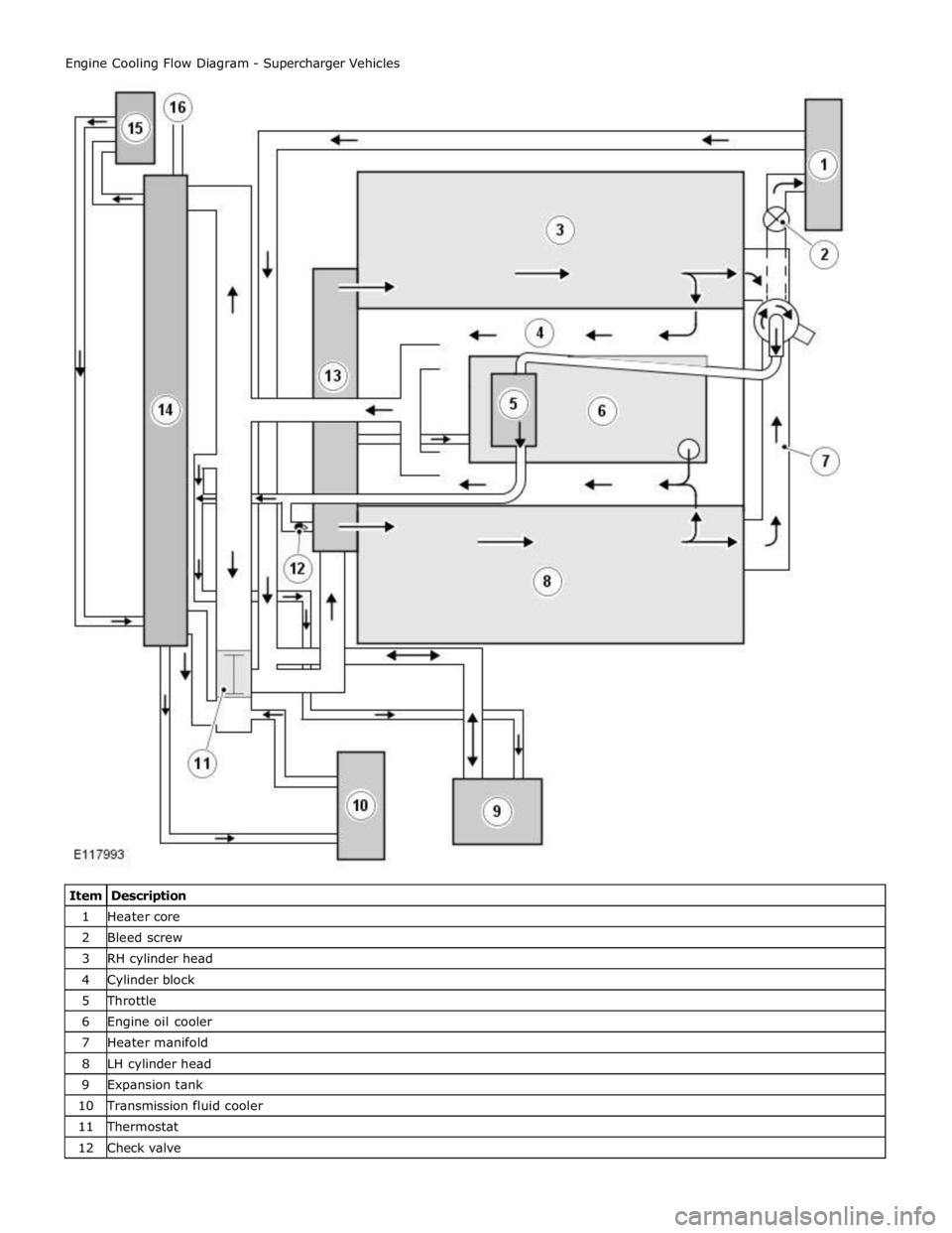
1 Heater core 2 Bleed screw 3 RH cylinder head 4 Cylinder block 5 Throttle 6 Engine oil cooler 7 Heater manifold 8 LH cylinder head 9 Expansion tank 10 Transmission fluid cooler 11 Thermostat 12 Check valve
Page 1114 of 3039

14 Radiator 15 Auxiliary radiator 16 Connection with supercharger cooling system
System Operation
When the engine is running, the coolant is circulated around the engine cooling system by the coolant pump. From the coolant
pump, coolant flows through the cylinder heads and the engine oil cooler into the cylinder block and the heater manifold.
In the cylinder block, the coolant flows forwards to the outlet tube. When the coolant is cold, the thermostat is closed and the
coolant flows direct from the outlet tube back to the coolant pump. Once the coolant reaches operating temperature the
thermostat begins to open, to control system temperature, and coolant flows from the outlet tube to the coolant pump via the
radiator and, on SC (supercharger) vehicles, the auxiliary radiator. When the thermostat is open, the coolant flow through the
radiator(s) also generates a coolant flow through the transmission fluid cooler.
From the heater manifold the coolant flows through the electronic throttle and the heater core, in parallel circuits that are
unaffected by the position of the thermostat. From the electronic throttle, the coolant merges with bleed coolant from the
coolant pump and the outlet tube and flows to the expansion tank. From the heater core, the coolant flows back to the inlet of
the coolant pump.
Expansion and contraction of the coolant is accommodated by an air space in the expansion tank and the compliance of the
flexible hoses.
If the coolant level in the expansion tank decreases below a predetermined value, the level sensor connects a ground to the
instrument cluster, which activates the appropriate warning. For additional information, refer to 413-01 Instrument Cluster.
The cooling fan is operated by a fan control module integrated into the cooling fan motor. The fan control module regulates the
voltage, and thus speed, of the cooling fan motor in response to a PWM (pulse width modulation) signal from the ECM (engine
control module).
The cooling fan receives a battery feed and an ignition feed from the EJB (engine junction box). The ignition feed is supplied
from the main relay in the EJB, which is controlled by the ECM.
The ECM calculates the required fan speed from the engine temperature, A/C (air conditioning) system pressure and transmission fluid temperature. Under hot operating conditions, the fan may continue to operate for 4 minutes after the engine
has been switched off.
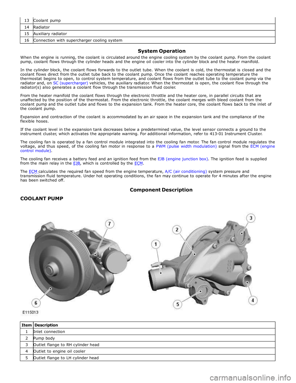
COOLANT PUMP Component Description
Item Description 1 Inlet connection 2 Pump body 3 Outlet flange to RH cylinder head 4 Outlet to engine oil cooler 5 Outlet flange to LH cylinder head