2010 JAGUAR XFR Throttle
[x] Cancel search: ThrottlePage 1369 of 3039

Published: 16-Sep-2013
Electronic Engine Controls - V8 S/C 5.0L Petrol - Electronic Engine Controls
Diagnosis and Testing
Principle of Operation
For a detailed description of electronic engine controls, refer to the relevant Description and Operation section of the workshop
manual. REFER to: (303-14D Electronic Engine Controls - V8 S/C 5.0L Petrol)
Electronic Engine Controls (Description and Operation), Electronic Engine Controls (Description and Operation), Electronic Engine Controls (Description and Operation).
Inspection and Verification
1. Verify the customer concern.
2. Visually inspect for obvious signs of damage and system integrity.
Visual Inspection
Mechanical Electrical
Engine oil level and condition
Cooling system coolant level
Fuel level
Fuel contamination/grade/quality
Throttle body
Front End Accessory Drive (FEAD) belt
Air cleaner condition
Fuses
Wiring harness
Electrical connector(s)
Sensor(s)
Engine Control Module
Transmission Control Module
3. If an obvious cause for an observed or reported concern is found, correct the cause (if possible) before proceeding to
the next step.
4. If the cause is not visually evident, verify the customer concern and refer to the Symptom Chart below, alternatively,
check for Diagnostic Trouble Codes (DTCs) and refer to the DTC Index.
Symptom Chart
Symptom Possible Cause Action Engine non-start Engine does not crank
Security system /Immobilizer
engaged
Engine in shut-down mode
ECM relay
Battery
Starting system
Engine seized
Check that the security system is disarmed
Read DTCs and refer to DTC Index in this
section for ECM relay tests
Ensure the battery is in fully charged and
serviceable condition
For starting system tests refer to the
relevant section of the workshop manual
For engine system tests refer to the relevant
section of the workshop manual Engine cranks, but does not fire
Engine breather system
disconnected/restricted
Ignition system
Fuel system
Electronic engine controls
Ensure the engine breather system is free
from restriction and is correctly installed
For ignition system tests refer to the
relevant section of the workshop manual
For fuel system tests refer to the relevant
section of the workshop manual
Read DTCs and refer to DTC Index in this
section for electronic engine control tests Engine cranks and fires, but will not
start
Evaporative emissions purge
valve
Fuel pump
Spark plugs
Ignition coil failure(s)
For purge valve tests refer to the relevant
section of the workshop manual
For fuel system tests refer to the relevant
section of the workshop manual
For ignition system tests refer to the
relevant section of the workshop manual Difficult to start Difficult cold start
Check engine coolant
level/anti-freeze content
Battery
Electronic engine controls
Exhaust gas recirculation
Check the engine coolant level and
condition. Refer to the relevant sections of
the workshop manual
Ensure the battery is in a fully charged and
serviceable condition. Refer to the battery
Page 1371 of 3039

Symptom Possible Cause Action Engine stalls on overrun
ECM relay
Throttle position (TP)
sensors
Read DTCs and refer to DTC Index in this
section for ECM relay and TP sensor tests Engine stalls at steady speed
ECM relay
crankshaft position sensor
TP sensors
Read DTCs and refer to DTC Index in this
section for ECM relay, crankshaft position
sensor, and TP sensor tests Engine stalls with speed control
enabled
ECM relay
Read DTCs and refer to DTC Index in this
section for ECM relay tests Engine stalls when manoeuvring
ECM relay
TP sensors
Additional engine loads
(PAS, air conditioning, etc)
Transmission malfunction
CAN malfunction
Read DTCs and refer to DTC Index in this
section for ECM relay, and TP sensor tests
Check for excessive loads being placed on
the engine from PAS, air conditioning
systems etc.
Refer to the workshop manual or
transmission troubleshooting guide for
transmission system tests.
Refer to the relevant section of the
workshop manual and the electrical wiring
diagrams to perform CAN network tests. Poor driveability Engine hesitates/poor acceleration
Fuel pressure, fuel pump,
fuel lines
Injector leak
Air leakage
Electronic engine controls
Ignition system
EGR valve stuck
Transmission malfunction
Restricted pedal travel
(carpet, etc)
For fuel system tests refer to the relevant
section of the workshop manual
Carry out fuel injector leak tests, install new
injectors as necessary.
Check for leakage from air intake system
Read DTCs and refer to DTC Index in this
section for electronic engine control tests
For ignition system tests refer to the
relevant section of the workshop manual
Refer to the relevant section of the
workshop manual and check the Exhaust Gas
Recirculation (EGR) valve and associated
hoses and connections.
Refer to the workshop manual or
transmission troubleshooting guide for
transmission system tests.
Ensure accelerator pedal is free from
restriction Engine backfires
Fuel pump, fuel lines
Air leakage
Electronic engine controls
Ignition system
Sticking variable camshaft
timing (VCT) hub
For fuel system tests refer to the relevant
section of the workshop manual
Check for leakage from air intake system
Read DTCs and refer to DTC Index in this
section for electronic engine control tests
For ignition system tests refer to the
relevant section of the workshop manual
Read DTCs and refer to DTC Index in this
section for VCT system tests Engine surges
Fuel pump, fuel lines
Electronic engine controls
Ignition system
For fuel system tests refer to the relevant
section of the workshop manual
Read DTCs and refer to DTC Index in this
section for electronic engine control tests
For ignition system tests refer to the
relevant section of the workshop manual Engine detonates/knocks
Electronic engine controls
Fuel pump, fuel lines, fuel
quality
Air leakage
Sticking VCT hub
Read DTCs and refer to DTC Index in this
section for electronic engine control tests
For fuel system tests refer to the relevant
section of the workshop manual
Check for leakage from air intake system
Read DTCs and refer to DTC Index in this
section for VCT system tests www.JagDocs.com
Page 1372 of 3039
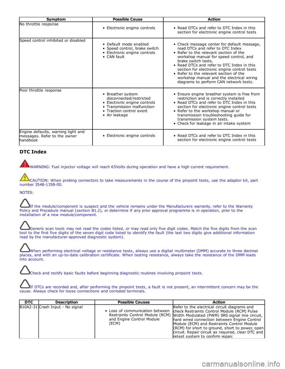
Symptom Possible Cause Action No throttle response
Electronic engine controls
Read DTCs and refer to DTC Index in this
section for electronic engine control tests Speed control inhibited or disabled
Default mode enabled
Speed control, brake switch
Electronic engine controls
CAN fault
Check message center for default message,
read DTCs and refer to DTC Index
Refer to the relevant section of the
workshop manual for speed control, and
brake switch tests.
Read DTCs and refer to DTC Index in this
section for electronic engine control tests
Refer to the relevant section of the
workshop manual and the electrical wiring
diagrams to perform CAN network tests. Poor throttle response
Breather system
disconnected/restricted
Electronic engine controls
Transmission malfunction
Traction control event
Air leakage
Ensure engine breather system is free from
restriction and is correctly installed
Read DTCs and refer to DTC Index in this
section for electronic engine control tests
Refer to the workshop manual or
transmission troubleshooting guide for
transmission system tests.
Check for leakage in air intake system Engine defaults, warning light and
messages. Refer to the owner
handbook
Electronic engine controls
Read DTCs and refer to DTC Index in this
section for electronic engine control tests DTC Index
WARNING: Fuel injector voltage will reach 65Volts during operation and have a high current requirement.
CAUTION: When probing connectors to take measurements in the course of the pinpoint tests, use the adaptor kit, part
number 3548-1358-00.
NOTES:
If the module/component is suspect and the vehicle remains under the Manufacturers warranty, refer to the Warranty
Policy and Procedure manual (section B1.2), or determine if any prior approval programme is in operation, prior to the
installation of a new module/component.
Generic scan tools may not read the codes listed, or may read only five digit codes. Match the five digits from the scan
tool to the first five digits of the seven digit code listed to identify the fault (the last two digits give additional information
read by the manufacturer-approved diagnostic system).
When performing electrical voltage or resistance tests, always use a digital multimeter (DMM) accurate to three decimal
places, and with an up-to-date calibration certificate. When testing resistance, always take the resistance of the DMM leads
into account.
Check and rectify basic faults before beginning diagnostic routines involving pinpoint tests.
If DTCs are recorded and, after performing the pinpoint tests, a fault is not present, an intermittent concern may be the
cause. Always check for loose connections and corroded terminals.
DTC Description Possible Causes Action B10A2-31 Crash Input - No signal
Loss of communication between
Restraints Control Module (RCM)
and Engine Control Module
(ECM) Refer to the electrical circuit diagrams and
check Restraints Control Module (RCM) Pulse
Width Modulated (PWM) SRS signal line circuit,
hard wired connection between Engine Control
Module (ECM) and Restraints Control Module
(RCM) for short to ground, short to power, open
circuit. Repair circuit as required, clear DTC and
retest system to confirm repair.
Page 1374 of 3039
Published: 11-May-2011
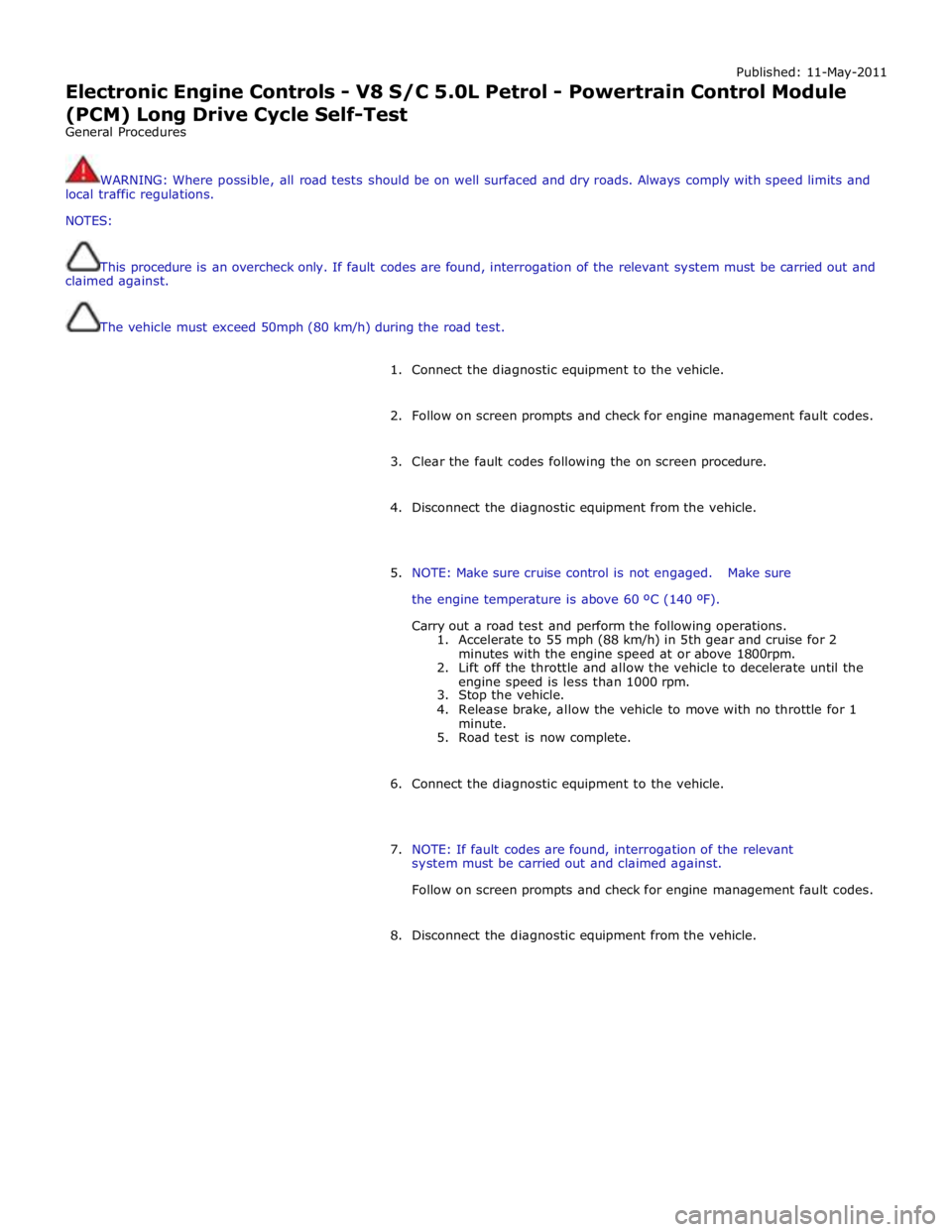
Electronic Engine Controls - V8 S/C 5.0L Petrol - Powertrain Control Module
(PCM) Long Drive Cycle Self-Test
General Procedures
WARNING: Where possible, all road tests should be on well surfaced and dry roads. Always comply with speed limits and
local traffic regulations.
NOTES:
This procedure is an overcheck only. If fault codes are found, interrogation of the relevant system must be carried out and
claimed against.
The vehicle must exceed 50mph (80 km/h) during the road test.
1. Connect the diagnostic equipment to the vehicle.
2. Follow on screen prompts and check for engine management fault codes.
3. Clear the fault codes following the on screen procedure.
4. Disconnect the diagnostic equipment from the vehicle.
5. NOTE: Make sure cruise control is not engaged. Make sure
the engine temperature is above 60 ºC (140 ºF).
Carry out a road test and perform the following operations.
1. Accelerate to 55 mph (88 km/h) in 5th gear and cruise for 2
minutes with the engine speed at or above 1800rpm.
2. Lift off the throttle and allow the vehicle to decelerate until the
engine speed is less than 1000 rpm.
3. Stop the vehicle.
4. Release brake, allow the vehicle to move with no throttle for 1
minute.
5. Road test is now complete.
6. Connect the diagnostic equipment to the vehicle.
7. NOTE: If fault codes are found, interrogation of the relevant
system must be carried out and claimed against.
Follow on screen prompts and check for engine management fault codes.
8. Disconnect the diagnostic equipment from the vehicle.
Page 1412 of 3039
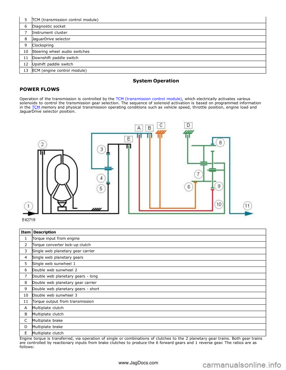
TCM (transmission control module) 6 Diagnostic socket 7 Instrument cluster 8 JaguarDrive selector 9 Clockspring 10 Steering wheel audio switches 11 Downshift paddle switch 12 Upshift paddle switch 13 ECM (engine control module)
POWER FLOWS System Operation
Operation of the transmission is controlled by the TCM (transmission control module), which electrically activates various
solenoids to control the transmission gear selection. The sequence of solenoid activation is based on programmed information
in the TCM memory and physical transmission operating conditions such as vehicle speed, throttle position, engine load and JaguarDrive selector position.
Item Description 1 Torque input from engine 2 Torque converter lock-up clutch 3 Single web planetary gear carrier 4 Single web planetary gears 5 Single web sunwheel 1 6 Double web sunwheel 2 7 Double web planetary gears - long 8 Double web planetary gear carrier 9 Double web planetary gears - short 10 Double web sunwheel 3 11 Torque output from transmission A Multiplate clutch B Multiplate clutch C Multiplate brake D Multiplate brake E Multiplate clutch Engine torque is transferred, via operation of single or combinations of clutches to the 2 planetary gear trains. Both gear trains
are controlled by reactionary inputs from brake clutches to produce the 6 forward gears and 1 reverse gear. The ratios are as
follows: www.JagDocs.com
Page 1436 of 3039
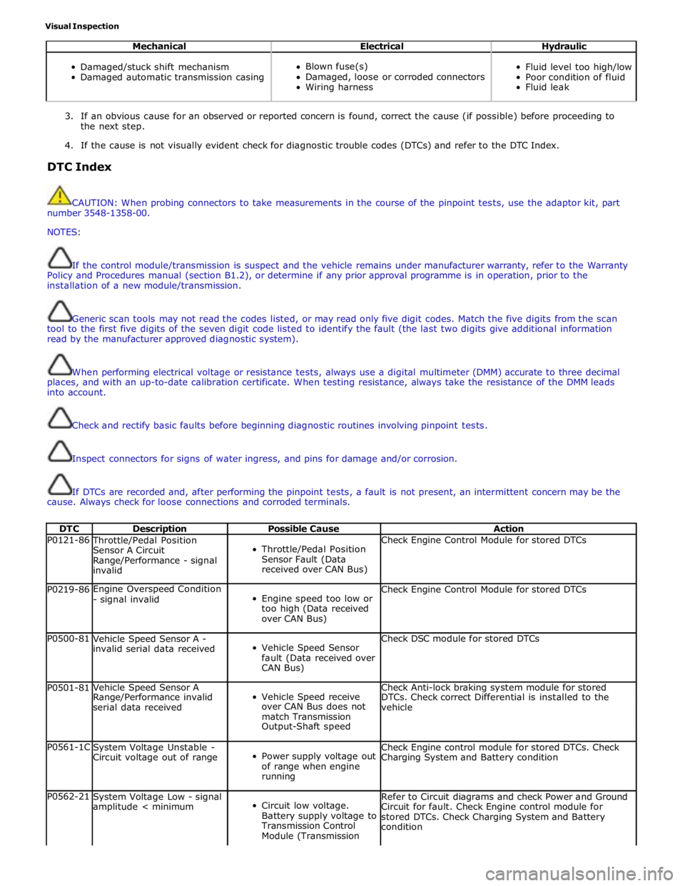
Visual Inspection
Mechanical Electrical Hydraulic
Damaged/stuck shift mechanism
Damaged automatic transmission casing
Blown fuse(s)
Damaged, loose or corroded connectors
Wiring harness
Fluid level too high/low
Poor condition of fluid
Fluid leak
3. If an obvious cause for an observed or reported concern is found, correct the cause (if possible) before proceeding to
the next step.
4. If the cause is not visually evident check for diagnostic trouble codes (DTCs) and refer to the DTC Index.
DTC Index
CAUTION: When probing connectors to take measurements in the course of the pinpoint tests, use the adaptor kit, part
number 3548-1358-00.
NOTES:
If the control module/transmission is suspect and the vehicle remains under manufacturer warranty, refer to the Warranty
Policy and Procedures manual (section B1.2), or determine if any prior approval programme is in operation, prior to the
installation of a new module/transmission.
Generic scan tools may not read the codes listed, or may read only five digit codes. Match the five digits from the scan
tool to the first five digits of the seven digit code listed to identify the fault (the last two digits give additional information
read by the manufacturer approved diagnostic system).
When performing electrical voltage or resistance tests, always use a digital multimeter (DMM) accurate to three decimal
places, and with an up-to-date calibration certificate. When testing resistance, always take the resistance of the DMM leads
into account.
Check and rectify basic faults before beginning diagnostic routines involving pinpoint tests.
Inspect connectors for signs of water ingress, and pins for damage and/or corrosion.
If DTCs are recorded and, after performing the pinpoint tests, a fault is not present, an intermittent concern may be the
cause. Always check for loose connections and corroded terminals.
DTC Description Possible Cause Action P0121-86 Throttle/Pedal Position
Sensor A Circuit
Range/Performance - signal
invalid
Throttle/Pedal Position
Sensor Fault (Data
received over CAN Bus) Check Engine Control Module for stored DTCs P0219-86 Engine Overspeed Condition
- signal invalid
Engine speed too low or
too high (Data received
over CAN Bus) Check Engine Control Module for stored DTCs P0500-81
Vehicle Speed Sensor A -
invalid serial data received
Vehicle Speed Sensor
fault (Data received over
CAN Bus) Check DSC module for stored DTCs P0501-81 Vehicle Speed Sensor A
Vehicle Speed receive Check Anti-lock braking system module for stored Range/Performance invalid DTCs. Check correct Differential is installed to the serial data received over CAN Bus does not
vehicle match Transmission Output-Shaft speed P0561-1C
System Voltage Unstable -
Circuit voltage out of range
Power supply voltage out
of range when engine
running Check Engine control module for stored DTCs. Check
Charging System and Battery condition P0562-21
System Voltage Low - signal
amplitude < minimum
Circuit low voltage.
Battery supply voltage to
Transmission Control
Module (Transmission Refer to Circuit diagrams and check Power and Ground
Circuit for fault. Check Engine control module for
stored DTCs. Check Charging System and Battery
condition
Page 1565 of 3039
Published: 01-Aug-2012
Fuel System - General Information - Fuel System Pressure Release V8 5.0L
Petrol/V8 S/C 5.0L Petrol
General Procedures
Draining
1. Remove the fuel pump fuse.
2. Remove the fuel filler cap.
3. CAUTION: When depressurising the fuel system, make sure that
there is no throttle input. Failure to follow this instruction may cause
damage to the vehicle.
Start the engine and allow it to idle until the engine stalls.
4. Crank the engine for approximately five seconds to make sure that the
fuel rail pressure is released.
Filling
1. NOTE: Make sure all repairs have been carried out before
proceeding to the following steps.
Install the fuel pump fuse.
2. Install the fuel filler cap.
3. Read and clear stored DTC fault codes.
Page 1586 of 3039
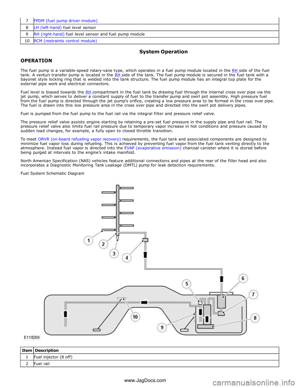
8 LH (left-hand) fuel level sensor 9 RH (right-hand) fuel level sensor and fuel pump module 10 RCM (restraints control module)
OPERATION System Operation
The fuel pump is a variable-speed rotary-vane type, which operates in a fuel pump module located in the RH side of the fuel tank. A venturi transfer pump is located in the RH side of the tank. The fuel pump module is secured in the fuel tank with a bayonet style locking ring that is welded into the tank structure. The fuel pump module has an integral top plate for the
external pipe work and electrical connectors.
Fuel level is biased towards the RH compartment in the fuel tank by drawing fuel through the internal cross over pipe via the jet pump, which serves to deliver a constant supply of fuel to the transfer pump and swirl pot assembly. High pressure fuel
from the fuel pump is directed through the jet pump's orifice, creating a low pressure area to be formed in the cross over pipe.
The fuel is drawn into this low pressure area in the cross over pipe and directed into the swirl pot delivery pipes.
Fuel is pumped from the fuel pump to the fuel rail via the integral filter and pressure relief valve.
The pressure relief valve assists engine starting by retaining a pre-set fuel pressure in the supply pipe and fuel rail. The
pressure relief valve also limits fuel rail pressure due to temporary vapor increase in hot conditions and pressure caused by
sudden load changes, for example, a fully open to closed throttle transition.
To meet ORVR (on-board refueling vapor recovery) requirements, the fuel tank and associated components are designed to
minimize fuel vapor loss during refueling. This is achieved by preventing fuel vapor from the fuel tank venting directly to the
atmosphere. Instead fuel vapor is directed into the EVAP (evaporative emission) charcoal canister where it is stored before
being purged at intervals to the engine’s intake manifold.
North American Specification (NAS) vehicles feature additional connections and pipes at the rear of the filler head and also
incorporates a Diagnostic Monitoring Tank Leakage (DMTL) pump for leak detection requirements.
Fuel System Schematic Diagram
Item Description 1 Fuel injector (8 off) 2 Fuel rail www.JagDocs.com