2010 JAGUAR XFR Throttle
[x] Cancel search: ThrottlePage 1642 of 3039

longitudinal axis of the vehicle. The radar operates at millimetric wavelengths (76 - 77 GHz) and transmits a frequency
modulated continuous wave signal at a relatively low power level (no high power pulses).
With the ignition ON, the adaptive speed control module is powered up but no radar transmissions are emitted until the
vehicle is in motion.
In follow mode a set speed is selected in the normal speed control manner and this speed is maintained until a slower vehicle
is encountered in the lane ahead. When the vehicle ahead comes within the effective range of the radar sensor, the system
identifies it as a target vehicle and an icon is illuminated on the instrument cluster to indicate that the system is in "follow
mode". When the distance between the two vehicles closes to a set time gap, the adaptive speed control system closes the
throttle and if necessary applies the brakes to maintain the set time gap. Follow mode is effectively a closed loop system. If
several vehicles are ahead, the closest vehicle is chosen as the target to follow. If the target vehicle moves out of radar range,
or if either vehicle changes lane or drops below the minimum operating speed, the system exits follow mode and the follow
mode icon is extinguished. The adaptive speed control system will only raise its speed to the originally set speed, it will not
accelerate past this speed to maintain a time gap.
Driver operation of the foot brake or control switches will immediately cancel adaptive speed control.
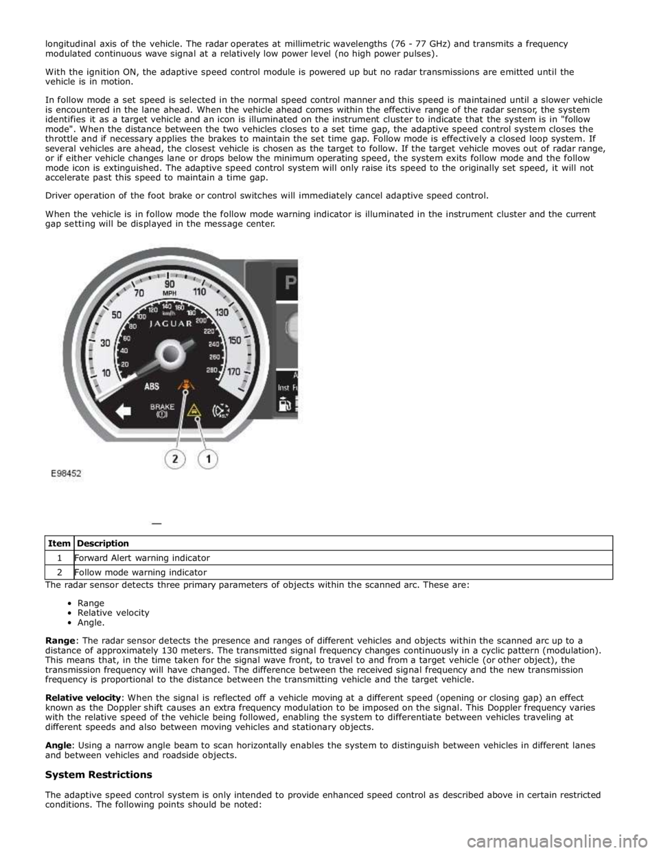
When the vehicle is in follow mode the follow mode warning indicator is illuminated in the instrument cluster and the current
gap setting will be displayed in the message center.
The radar sensor detects three primary parameters of objects within the scanned arc. These are:
Range
Relative velocity
Angle.
Range: The radar sensor detects the presence and ranges of different vehicles and objects within the scanned arc up to a
distance of approximately 130 meters. The transmitted signal frequency changes continuously in a cyclic pattern (modulation).
This means that, in the time taken for the signal wave front, to travel to and from a target vehicle (or other object), the
transmission frequency will have changed. The difference between the received signal frequency and the new transmission
frequency is proportional to the distance between the transmitting vehicle and the target vehicle.
Relative velocity: When the signal is reflected off a vehicle moving at a different speed (opening or closing gap) an effect
known as the Doppler shift causes an extra frequency modulation to be imposed on the signal. This Doppler frequency varies
with the relative speed of the vehicle being followed, enabling the system to differentiate between vehicles traveling at
different speeds and also between moving vehicles and stationary objects.
Angle: Using a narrow angle beam to scan horizontally enables the system to distinguish between vehicles in different lanes
and between vehicles and roadside objects.
System Restrictions
The adaptive speed control system is only intended to provide enhanced speed control as described above in certain restricted
conditions. The following points should be noted: Item Description 1 Forward Alert warning indicator 2 Follow mode warning indicator
Page 1645 of 3039

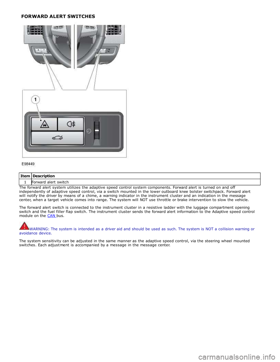
Item Description 1 Forward alert switch The forward alert system utilizes the adaptive speed control system components. Forward alert is turned on and off
independently of adaptive speed control, via a switch mounted in the lower outboard knee bolster switchpack. Forward alert
will notify the driver by means of a chime, a warning indicator in the instrument cluster and an indication in the message
center, when a target vehicle comes into range. The system will NOT use throttle or brake intervention to slow the vehicle.
The forward alert switch is connected to the instrument cluster in a resistive ladder with the luggage compartment opening
switch and the fuel filler flap switch. The instrument cluster sends the forward alert information to the Adaptive speed control
module on the CAN bus.
WARNING: The system is intended as a driver aid and should be used as such. The system is NOT a collision warning or
avoidance device.
The system sensitivity can be adjusted in the same manner as the adaptive speed control, via the steering wheel mounted
switches. Each adjustment is accompanied by a message in the message center. FORWARD ALERT SWITCHES
Page 1646 of 3039

Published: 08-Nov-2013
Speed Control - V8 5.0L Petrol/V8 S/C 5.0L Petrol - Speed Control
Diagnosis and Testing
Principles of Operation
For a detailed description of the speed control system, refer to the relevant Description and Operation sections in the
workshop manual.
Inspection and Verification
CAUTION: Diagnosis by substitution from a donor vehicle is NOT acceptable. Substitution of control modules does not
guarantee confirmation of a fault, and may also cause additional faults in the vehicle being tested and/or the donor vehicle.
1. Verify the customer concern.
2. Visually inspect for obvious signs of damage and system integrity.
Visual Inspection
Mechanical Electrical
Speed control sensor
Ensure the speed control sensor is free from obstructions
Speed control module
Brake switch
Fuses
Wiring harness
Electrical connector(s)
Steering wheel switches
Brake switch
Speed control sensor
Speed control module
Engine Control Module (ECM)
3. If an obvious cause for an observed or reported concern is found, correct the cause (if possible) before proceeding to
the next step.
4. If the cause is not visually evident, verify the symptom and refer to the Symptom Chart, alternatively, check for
Diagnostic Trouble Codes (DTCs) and refer to the DTC Index.
Speed Control Sensor Adjustment (vehicles with adaptive system installed)
An incorrectly aligned speed control sensor can cause incorrect system operation. Before starting any repair work on the speed
control system, on vehicles with the adaptive system installed, check speed control sensor for correct vertical alignment, and
carry out speed control sensor alignment procedure using manufacturer approved diagnostic system.
Symptom Chart
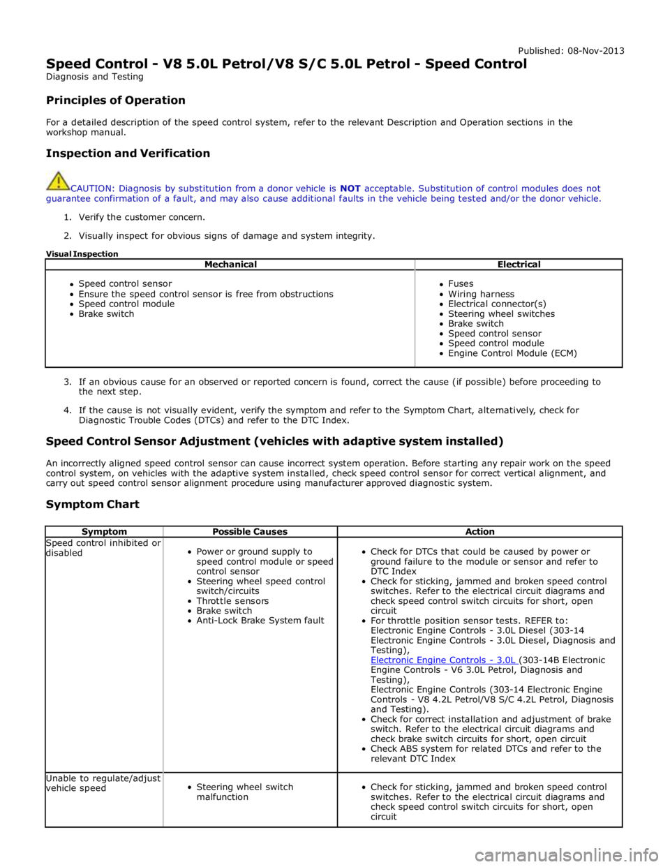
Symptom Possible Causes Action Speed control inhibited or
disabled
Power or ground supply to
speed control module or speed
control sensor
Steering wheel speed control
switch/circuits
Throttle sensors
Brake switch
Anti-Lock Brake System fault
Check for DTCs that could be caused by power or
ground failure to the module or sensor and refer to
DTC Index
Check for sticking, jammed and broken speed control
switches. Refer to the electrical circuit diagrams and
check speed control switch circuits for short, open
circuit
For throttle position sensor tests. REFER to:
Electronic Engine Controls - 3.0L Diesel (303-14
Electronic Engine Controls - 3.0L Diesel, Diagnosis and
Testing),
Electronic Engine Controls - 3.0L (303-14B Electronic Engine Controls - V6 3.0L Petrol, Diagnosis and
Testing),
Electronic Engine Controls (303-14 Electronic Engine
Controls - V8 4.2L Petrol/V8 S/C 4.2L Petrol, Diagnosis
and Testing).
Check for correct installation and adjustment of brake
switch. Refer to the electrical circuit diagrams and
check brake switch circuits for short, open circuit
Check ABS system for related DTCs and refer to the
relevant DTC Index Unable to regulate/adjust
vehicle speed
Steering wheel switch
malfunction
Check for sticking, jammed and broken speed control
switches. Refer to the electrical circuit diagrams and
check speed control switch circuits for short, open
circuit
Page 1785 of 3039

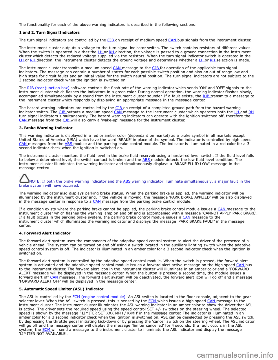
The functionality for each of the above warning indicators is described in the following sections:
1 and 2. Turn Signal Indicators
The turn signal indicators are controlled by the CJB on receipt of medium speed CAN bus signals from the instrument cluster.
The instrument cluster outputs a voltage to the turn signal indicator switch. The switch contains resistors of different values.
When the switch is operated in either the LH or RH direction, the voltage is passed to a ground connection in the instrument cluster which detects the reduced voltage supplied via the resistors. When the turn signal indicator switch is operated in the
LH or RH direction, the instrument cluster detects the ground voltage and determines whether a LH or RH selection is made.
The instrument cluster transmits a medium speed CAN message to the CJB for operation of the applicable turn signal indicators. The message can contain a number of states for each possible switch position and also an out of range low and
high state for circuit faults and an initial value for the switch neutral position. The turn signal indicators are not subject to the
3 second indicator check when the ignition is switched on.
The RJB (rear junction box) software controls the flash rate of the warning indicator which sends 'ON' and 'OFF' signals to the
instrument cluster which flashes the indicators in a green color. During normal operation, the warning indicator flashes slowly,
accompanied simultaneously by a sound from the instrument cluster sounder. If a fault exists, the RJB transmits a message to the instrument cluster which responds by displaying an appropriate message in the message center.
The hazard warning indicators are controlled by the CJB on receipt of a completed ground path from the hazard warning indicator switch. The CJB outputs a medium speed CAN message to the instrument cluster which operates both the LH and RH turn signal indicators simultaneously. The hazard warning indicators can operate with the ignition switched off, therefore the
CAN message from the CJB will also carry a 'wake-up' message for the instrument cluster. 3. Brake Warning Indicator
This warning indicator is displayed in a red or amber color (dependant on market) as a brake symbol in all markets except
United States of America (USA) which have the word 'BRAKE' in place of the symbol. The indicator is controlled by high speed
CAN messages from the ABS module and the parking brake control module. The indicator is illuminated in a red color for a 3 second indicator check when the ignition is switched on.
The instrument cluster monitors the fluid level in the brake fluid reservoir using a hardwired level switch. If the fluid level falls
to below a determined level, the switch contact is broken and the ABS module detects the low fluid level condition. The instrument cluster illuminates the warning indicator and simultaneously displays a 'BRAKE FLUID LOW' message in the
message center.
NOTE: If both the brake warning indicator and the ABS warning indicator illuminate simultaneously, a major fault in the brake system will have occurred.
The warning indicator also displays parking brake status. When the parking brake is applied, the warning indicator will be
illuminated by the instrument cluster and, if the vehicle is moving, the message 'PARK BRAKE APPLIED' will be also displayed
in the message center in response to a CAN message from the parking brake control module.
If a condition exists where the parking brake cannot be applied, the parking brake control module issues a CAN message to the instrument cluster which flashes the warning lamp on and off and is accompanied with a message 'CANNOT APPLY PARK BRAKE'.
If a fault occurs in the parking brake system, the parking brake control module issues a CAN message to the instrument cluster which illuminates the warning indicator and displays the message 'PARK BRAKE FAULT' in the message
center.
4. Forward Alert Indicator
The forward alert system uses the components of the adaptive speed control system to alert the driver of the presence of a
vehicle ahead. The system can be turned on and off using a switch located in the auxiliary lighting switch when the adaptive
speed control system is off. The indicator is illuminated in an amber color for a 3 second indicator check when the ignition is
switched on.
The forward alert system is controlled by the adaptive speed control module. When the switch is pressed, the forward alert
system is activated and the adaptive speed control module issues a forward alert active message on the high speed CAN bus to the instrument cluster. The forward alert icon in the instrument cluster will illuminate in an amber color and a 'FORWARD
ALERT' message will be displayed in the message center. When the button is pressed a second time, the module issues a
forward alert off CAN message. The forward alert system will be deactivated, the forward alert icon will go off and a message 'FORWARD ALERT OFF' will be displayed in the message center.
5. Automatic Speed Limiter (ASL) Indicator
The ASL is controlled by the ECM (engine control module). An ASL switch is located in the floor console, adjacent to the gear
selector lever. When the ASL switch is pressed, this is sensed by the ECM which issues a high speed CAN message to the instrument cluster. The instrument cluster illuminates the ASL warning indicator in an amber color to show the driver that ASL
is active. The driver sets the required speed using the speed control SET +/- switches on the steering wheel. The selected
speed is shown by the message ' LIMITER SET XXX MPH / K/MH' in the message center. The indicator is illuminated in an
amber color for a 3 second indicator check when the ignition is switched on. ASL can be deselected by pressing the ASL switch,
by depressing the throttle pedal initiating kick-down or by pressing the 'cancel' switch on the steering wheel. The ASL indicator
will go off and the message center will display the message 'limiter cancelled' for 4 seconds. If a fault occurs in the ASL
system, the ECM will send a message to the instrument cluster to illuminate the ASL indicator and display the message 'LIMITER NOT AVAILABLE'.
Page 1871 of 3039

Published: 21-Dec-2012
Battery and Charging System - General Information - Quiescent Drain
Description and Operation
VEHICLE QUIESCENT CURRENT TESTING
On vehicles fitted with a Battery Monitoring System (BMS), the diagnostic routine for quiescent drain testing in the approved
Jaguar or Land Rover diagnostic system should be utilized.
If a customer complains of a vehicle battery that discharges continuously or when left for a prolonged period of time, it is
recommended that a quiescent drain test is performed as described below.
The battery drain should be measured using the approved Jaguar or Land Rover diagnostic system or a Digital Multi-Meter
(DVOM). A procedure for quiescent drain measurement using the diagnostic system is available in the Diagnosis and Testing
section of the Workshop Manual. The vehicle should be in the locked/armed state (for example vehicle alarm fully armed), all
doors, engine and luggage compartment lids are open and latched (so as to appear closed from an electrical point of view).
The test should take place after the vehicle has entered shutdown mode. The time taken for this to occur after the ignition is
switched off varies according to model (Refer to the Topix On line resource for details).
When the vehicle is armed, the effect of the security system Light Emitting Diode (LED) flashing is to cause a pulsation in the
measured current drain. In this case, either the average current should be taken (using a Digital Multi- Meter (DVOM) with an
averaging system) or the current reading taken, ignoring the brief high current peaks.
EQUIPMENT
Approved Jaguar or Land Rover diagnostic system with current probeOR Digital Multi-Meter (DVOM) with current probe.
METHOD OF MEASUREMENT
Using an Approved Jaguar or Land Rover Diagnostic System.
1. Switch off all electrical loads and ensure that the ignition is off
2. Connect the current probe to the approved Jaguar or Land Rover diagnostic system
3. Calibrate the probe
4. Install a clamp around the battery lead/junction box lead
5. Go to the Quiescent Current Testing section in this procedure
Using a digital multimeter
Do not use an in-line DVOM to measure the quiescent drain on vehicles fitted with an electronic throttle (for example XK 2006
onwards). The current exceeds the maximum amount the fuse in the DVOM is capable of handling.
1. Switch off all electrical loads and ensure that the ignition is off
2. Connect the current probe to the digital multmeter
3. Calibrate the probe
4. Install a clamp around the battery lead/junction box lead
5. Go to the Quiescent Current Testing section in this procedure
QUIESCENT CURRENT TESTING
1. Switch ignition to ‘on’ or select ignition mode in keyless vehicles and switch to ‘off’ (do not crank)
2. Remove key from ignition switch (if equipped)
3. Open and latch all doors, hood and luggage compartment lid
4. Lock the vehicle using the remote function on the remote handset. (Single lock only to avoid volumetric alarm arming)
5. Remove any other potential electrical drains such as accessories plugged into accessory sockets
6. Record the amperage readings after the shutdown period referenced in the Topix on line resource for details. Note all
cars from 10MY onwards and XK from 07MY and XF from 08MY should be less than 30mA after 30 minutes
7. Record the final reading on the battery report form
The preferred method of testing following an excessive current consumption figure is to use a current probe around individual
junction box leads to the various suspected circuits to identify a potential cause. This is in preference to the old method of
removing fuses for the following reasons:
The drain may be caused by a module remaining active and preventing the quiescent drain from reducing to normal
levels
The drain may be caused by a relay winding that is activated. Pulling the fuse can allow this to ‘reset’ and the drain will
be lost and go un-diagnosed
QUIESCENT DRAIN - TYPICAL VALUES
NOTE: The quiescent drain after the initial shutdown period should not exceed the value shown in the table.
Jaguar Quiescent Drain Values
MODEL SHUT DOWN PERIOD (minutes) TYPICAL VALUES BATTERY DRAIN (mA) XJS 3.2 60 <30 Sovereign 3.2 60 <37.3