2010 JAGUAR XFR Can bus
[x] Cancel search: Can busPage 1882 of 3039
11 Secondary battery 12 Dual Battery Junction Box (DBJB) 13 Rear Junction Box (RJB) 14 Megafuse 15 Battery Junction box (BJB) 16 Primary battery
System Operation BATTERY MONITORING SYSTEM - TD4 2.2L DIESEL VEHICLES ONLY
Periodically the battery monitoring system module will instigate a self-calibration routine. To self calibrate, the battery
monitoring system first charges the battery to its full condition.
NOTE: If the vehicle is only driven for short periods the charging process could take a number of days to complete.
Once the battery is fully charged, the battery monitoring system will discharge the battery to approximately 75% of its full
state of charge, but never lower than 12.2 V. The time taken to complete this part of the routine is dependent on the electrical
load on the vehicle.
When the second part of the routine has been successfully completed, the battery monitoring system will return the battery to
its optimum level of charge. The optimum level of charge will be between 12.6 V and 15 V, depending on battery condition,
temperature and loading.
The battery monitoring system module also monitors the battery condition with the engine switched off. If a low voltage
condition is detected the module can request the infotainment system is switched off to protect battery voltage. Once the
infotainment system has been switched off, the vehicle must be run for at least 5 minutes to charge the battery before the
infotainment system can be operated with the engine switched off.
BATTERY MONITORING SYSTEM - SINGLE AND DUAL BATTERY SYSTEM VEHICLES
When the ignition is off (power mode 0), the BMS control module records the primary battery state of charge and begins to
monitor the battery condition from this point.
If the battery state of charge falls by 7%, the BMS control module will monitor the primary battery for 5 minutes. If after the 5
minute monitoring period, the primary battery charge has continued to fall due to the quiescent drain current being too high,
the BMS control module will determine that some control modules are still 'awake'. The BMS control module sends a shutdown
message on the LIN (local interconnect network) bus to the GWM (Gateway Module). The GWM sends a CAN (controller area
network) bus message on both the medium and high speed networks to all control modules, requesting them to shutdown.
The BMS control module will monitor the primary battery state of charge for a further 5 minutes and determine if the primary
battery state of charge is still dropping. If a quiescent drain current continues, the primary battery state of charge will
continue to drop. If the state of charge falls to 12% of the initial monitoring value, the BMS control module determines that
one or more control modules are still awake and a failure to respond to the shutdown request may indicate an error state
within the control module(s).
BMS Low Battery Warning and Energy Management Messages
The BMS continuously monitors the condition of the primary vehicle battery. If excessive battery discharge occurs, the system
will begin to shut down non-essential electrical systems in order to protect the battery.
If the BMS calculates that battery condition is not within set parameters, there are 3 messages that can be displayed, 2 on the
touch screen and 1 on the message center. These inform the user that the battery is either at a low level of charge or the
engine-off power consumption limit has been exceeded.
Low Battery - Please switch engine on or system will shutdown in 3 minutes: is displayed as a Warning on the
touch screen if the engine is not running. This indicates that the battery has fallen below a predefined threshold. As
soon as the battery is charged back above this threshold then the message will be removed.
Low Battery - Please start your engine is displayed on the message center if the engine is not running. This indicates
that the battery has fallen below a predefined threshold. As soon as the battery is charged back above this threshold
then the message will be removed or it can be manually removed by pressing 'OK'.
System will shut down in 3 minutes: is displayed as an Energy management on the touch screen if the engine is not
running, and system features are causing excessive battery discharge. After 3 minutes the BMS will begin shutting
down vehicle systems. Normal system operation will resume when the engine is started.
This is based on a percentage of battery capacity available for the customer to use with the engine off. The percentage can
change based upon several factors.
Once triggered, the resetting of this message will not occur until the vehicle is driven for 10 minutes with the engine running
(to allow the battery to recoup any lost charge). However, if the engine is run for less than 10 minutes, the message will only
be displayed after an additional 5 minutes with the ignition on but engine off.
BMS Control Module Self Calibration
Periodically the BMS control module will instigate a self-calibration routine. To self calibrate, the battery monitoring system www.JagDocs.com
Page 1883 of 3039
first charges the battery to its full condition.
NOTE: If the vehicle is only driven for short periods the charging process could take a number of days to complete.
Once the battery is fully charged, the BMS control module will discharge the battery to approximately 75% of its full state of
charge, but never lower than 12.2 V. The time taken to complete this part of the routine is dependent on the electrical load on
the vehicle.
When the second part of the routine has been successfully completed, the BMS control module will return the battery to its
optimum level of charge. The optimum level of charge will be between 12.6 V and 15 V, depending on battery condition,
temperature and loading.
The BMS control module also monitors the primary battery condition with the engine switched off. If a low voltage condition is
detected the BMS control module can request the infotainment system is switched off to protect battery voltage.
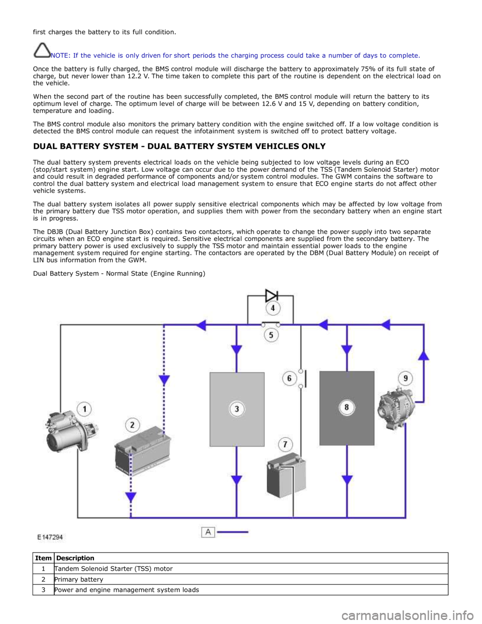
DUAL BATTERY SYSTEM - DUAL BATTERY SYSTEM VEHICLES ONLY
The dual battery system prevents electrical loads on the vehicle being subjected to low voltage levels during an ECO
(stop/start system) engine start. Low voltage can occur due to the power demand of the TSS (Tandem Solenoid Starter) motor
and could result in degraded performance of components and/or system control modules. The GWM contains the software to
control the dual battery system and electrical load management system to ensure that ECO engine starts do not affect other
vehicle systems.
The dual battery system isolates all power supply sensitive electrical components which may be affected by low voltage from
the primary battery due TSS motor operation, and supplies them with power from the secondary battery when an engine start
is in progress.
The DBJB (Dual Battery Junction Box) contains two contactors, which operate to change the power supply into two separate
circuits when an ECO engine start is required. Sensitive electrical components are supplied from the secondary battery. The
primary battery power is used exclusively to supply the TSS motor and maintain essential power loads to the engine
management system required for engine starting. The contactors are operated by the DBM (Dual Battery Module) on receipt of
LIN bus information from the GWM.
Dual Battery System - Normal State (Engine Running)
Item Description 1 Tandem Solenoid Starter (TSS) motor 2 Primary battery 3 Power and engine management system loads
Page 1884 of 3039
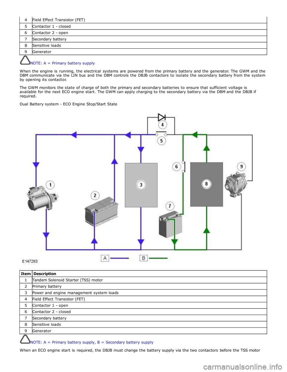
4 Field Effect Transistor (FET) 5 Contactor 1 - closed 6 Contactor 2 - open 7 Secondary battery 8 Sensitive loads 9 Generator
NOTE: A = Primary battery supply
When the engine is running, the electrical systems are powered from the primary battery and the generator. The GWM and the
DBM communicate via the LIN bus and the DBM controls the DBJB contactors to isolate the secondary battery from the system
by opening its contactor.
The GWM monitors the state of charge of both the primary and secondary batteries to ensure that sufficient voltage is
available for the next ECO engine start. The GWM can apply charging to the secondary battery via the DBM and the DBJB if
required.
Dual Battery system - ECO Engine Stop/Start State
Item Description 1 Tandem Solenoid Starter (TSS) motor 2 Primary battery 3 Power and engine management system loads 4 Field Effect Transistor (FET) 5 Contactor 1 - open 6 Contactor 2 - closed 7 Secondary battery 8 Sensitive loads 9 Generator
NOTE: A = Primary battery supply, B = Secondary battery supply
When an ECO engine start is required, the DBJB must change the battery supply via the two contactors before the TSS motor
Page 1885 of 3039

is operated to crank the engine. The GWM is connected to the ABS (Anti-lock Brake System) control module via the high speed
CAN bus. With the vehicle stationary and the engine off after an ECO engine stop, when the driver releases the brake pedal
the ABS control module senses the reduction in brake pressure. This change of brake pressure state is sent as a high speed
CAN message which is received by the GWM and the ECM. The GWM reacts within 105ms to instruct the DBM via the LIN bus
to operate the two contactors in the DBJB to supply the sensitive loads from the secondary battery and supply the TSS motor
direct from the primary battery.
When the engine is running and the generator is supplying power to the vehicle systems, the GWM again instructs the DBM to
operate the two contactors in the DBJB to supply all vehicle systems from the primary battery and the generator and to isolate
the secondary battery.
Secondary Battery Charging
The DBM also controls the charging of the secondary battery. The GWM contains electrical load management software and
monitors both batteries for their state of charge. The primary battery is monitored by the BMS control module which is
connected to the DBM via the LIN bus. The DBM communicates the primary battery condition to the GWM via a LIN bus
connection. The GWM sends a signal to the DBM via the LIN bus to instruct it to apply charging from the generator to the
secondary battery when required. The contactor 2 is closed by the DBJB to complete the secondary battery circuit, and the
generator output is applied to the secondary battery to charge it.
The generator output is controlled by the GWM which monitors and controls the electrical load management system. The
generator is connected to the GWM by a LIN bus allowing the GWM to control the output of the generator to maintain electrical
system load requirements and battery charging.
Electrical Load Management
The electrical load management is controlled by the GWM and the BMS control module.
The GWM will monitor the vehicle system power loads before and during an ECO engine stop.
Before an ECO engine stop, the GWM will transmit a signal to system control modules on the CAN bus to request a power save
on all electrical loads and set a minimum electrical value override. The GWM monitors the vehicle electrical loads and will
inhibit a ECO engine stop until the load current is at a value low enough to be supported by the secondary battery.
If the electrical loads cannot be reduced sufficiently, the GWM will inhibit the ECO engine stop.
When the engine is stopped after an ECO engine stop, the GWM will continue to monitor the primary battery state of charge.
If the primary or secondary battery voltage falls below 11.0V, a level which will result in degraded starting performance or
possible primary battery damage, the GWM will initiate an engine start.
System Inhibits
The ECO stop/start system is inhibited if the dual battery system is not be capable of preventing electrical loads on the
vehicle being subject to unacceptably low voltage levels during ECO stop/start operations due to a fault.
ECO stop/start inhibit monitoring of the primary battery is performed by the BMS control module. If the primary battery voltage
is too low to support an ECO stop/start, then the BMS control module will send a message to the GWM on the LIN bus to
suspend ECO stop/start.
The GWM monitors the secondary battery and the dual battery system components. Any fault found will cause the GWM to
inhibit ECO stop/start and the GWM will record a DTC (diagnostic trouble code).
Fault Diagnosis
The GWM performs passive and active diagnostics on the dual battery system to determine the status of the system
components.
Passive diagnostics can detect faults in the DBJB and can check for stuck open or closed contactors and failure of DBM
contactor command signals.
Active diagnostics is a routine to test the capability of the contactors to respond to open or close command signals sent from
the GWM to the DBM. This routine also checks the FET's (Field Effect Transistors) activate as required. (Refer to Dual Battery
Junction Box below for description of FET operation)
The GWM will also check the dual battery system components for faults in a controlled environment when the generator is
providing a charging output. This will ensure that the detection of a fault will not result in sensitive electrical loads being
subjected to low voltage which may occur during an ECO stop/start with a fault present.
The GWM will illuminate the charge warning indicator in the instrument cluster if fault is detected in the dual battery system
which will result in a degraded power supply.
If a fault is detected the GWM transmits a CAN message to inhibit ECO stop/start operation. In some cases it will record a
DTC, display a warning message in instrument cluster and also illuminate charge warning indicator.
PRIMARY BATTERY - ALL VEHICLES Component Description
The primary battery is located in a plastic tray under the luggage compartment floor in the right side of the luggage
compartment, adjacent to the spare wheel. The battery is vented via a tube which is connected with a T piece to the vent from
Page 1886 of 3039
the secondary battery (if fitted) and passes through a grommet in the floorpan.
On new vehicles the primary battery positive terminal is fitted with a transit relay. The transit relay must removed using the
correct process detailed in the Pre Delivery Inspection (PDI) manual.
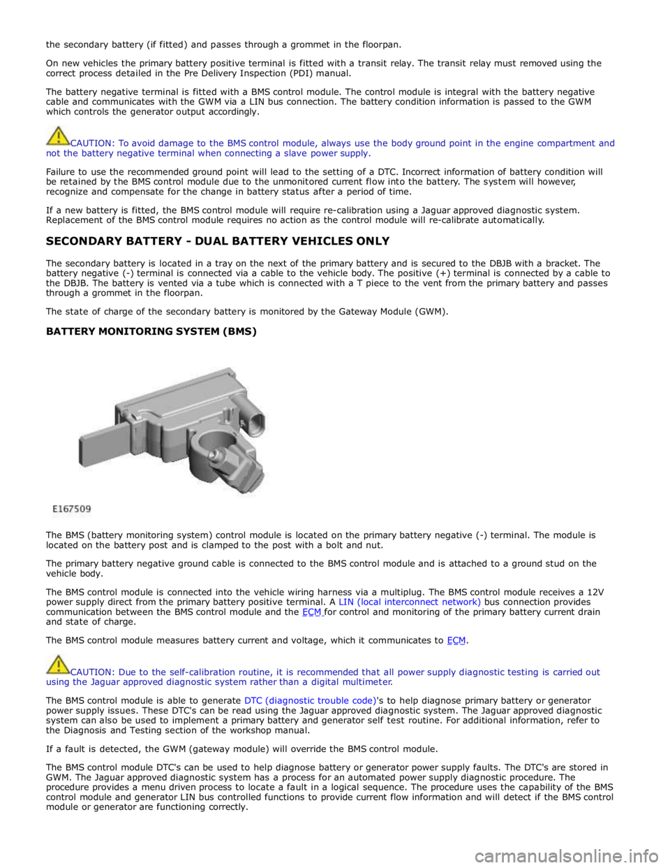
The battery negative terminal is fitted with a BMS control module. The control module is integral with the battery negative
cable and communicates with the GWM via a LIN bus connection. The battery condition information is passed to the GWM
which controls the generator output accordingly.
CAUTION: To avoid damage to the BMS control module, always use the body ground point in the engine compartment and
not the battery negative terminal when connecting a slave power supply.
Failure to use the recommended ground point will lead to the setting of a DTC. Incorrect information of battery condition will
be retained by the BMS control module due to the unmonitored current flow into the battery. The system will however,
recognize and compensate for the change in battery status after a period of time.
If a new battery is fitted, the BMS control module will require re-calibration using a Jaguar approved diagnostic system.
Replacement of the BMS control module requires no action as the control module will re-calibrate automatically.
SECONDARY BATTERY - DUAL BATTERY VEHICLES ONLY
The secondary battery is located in a tray on the next of the primary battery and is secured to the DBJB with a bracket. The
battery negative (-) terminal is connected via a cable to the vehicle body. The positive (+) terminal is connected by a cable to
the DBJB. The battery is vented via a tube which is connected with a T piece to the vent from the primary battery and passes
through a grommet in the floorpan.
The state of charge of the secondary battery is monitored by the Gateway Module (GWM).
BATTERY MONITORING SYSTEM (BMS)
The BMS (battery monitoring system) control module is located on the primary battery negative (-) terminal. The module is
located on the battery post and is clamped to the post with a bolt and nut.
The primary battery negative ground cable is connected to the BMS control module and is attached to a ground stud on the
vehicle body.
The BMS control module is connected into the vehicle wiring harness via a multiplug. The BMS control module receives a 12V
power supply direct from the primary battery positive terminal. A LIN (local interconnect network) bus connection provides
communication between the BMS control module and the ECM for control and monitoring of the primary battery current drain and state of charge.
The BMS control module measures battery current and voltage, which it communicates to ECM.
CAUTION: Due to the self-calibration routine, it is recommended that all power supply diagnostic testing is carried out
using the Jaguar approved diagnostic system rather than a digital multimeter.
The BMS control module is able to generate DTC (diagnostic trouble code)'s to help diagnose primary battery or generator
power supply issues. These DTC's can be read using the Jaguar approved diagnostic system. The Jaguar approved diagnostic
system can also be used to implement a primary battery and generator self test routine. For additional information, refer to
the Diagnosis and Testing section of the workshop manual.
If a fault is detected, the GWM (gateway module) will override the BMS control module.
The BMS control module DTC's can be used to help diagnose battery or generator power supply faults. The DTC's are stored in
GWM. The Jaguar approved diagnostic system has a process for an automated power supply diagnostic procedure. The
procedure provides a menu driven process to locate a fault in a logical sequence. The procedure uses the capability of the BMS
control module and generator LIN bus controlled functions to provide current flow information and will detect if the BMS control
module or generator are functioning correctly.
Page 1911 of 3039
Published: 11-May-2011
Generator and Regulator - V8 5.0L Petrol/V8 S/C 5.0L Petrol - Generator - System Operation and Component Description
Description and Operation
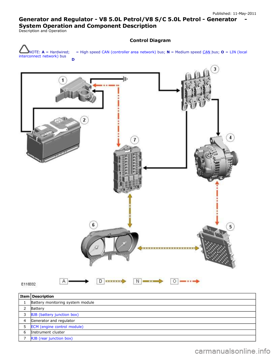
Control Diagram
NOTE: A = Hardwired;
interconnect network) bus
D = High speed CAN (controller area network) bus; N = Medium speed CAN bus; O = LIN (local
Item Description 1 Battery monitoring system module 2 Battery 3 BJB (battery junction box) 4 Generator and regulator 5 ECM (engine control module) 6 Instrument cluster 7 RJB (rear junction box)
Page 1945 of 3039
player is only compatible with standard CD's. All other versions of CD player are compatible with standard CDs and CDs with MP3 or WMA (windows media audio) files.
A portable audio module allows for the connection of a range of portable audio devices to the car’s audio system. The portable
audio module is controlled through the IAM (integrated audio module) and Touch-screen with play back through the car’s
speaker system. The introduction of this system allows the user to import their personal portable media player to interface
with the car, including iPod and other MP3 players, or USB mass storage devices such as memory sticks. MP3 players can also
be controlled through the Touch-screen if they are configured as mass storage devices. Details of how to do this will be
contained in the manufacturers instructions.
The chosen audio device can be plugged into the car using an interface panel located in the floor console between the front
seats. The interface includes a 3.5mm auxiliary jack-plug socket, a 12-volt power supply, a dedicated iPod connector with
charging function, plus a USB2 connector which allows connectivity for a wide variety of USB devices. The USB port also
provides a charging function although it does not support a USB hub. The maximum charging current supplied is 500ma. The
user can connect an iPod and USB device at the same time, changing the source via the Touch-screen. The non selected source
will still charge.
The Jaguar Sound System is the basic audio system which comprises of an IAM (integrated audio module) with no external
amplifier and 8 speakers.
The Jaguar 320W Premium Sound System has the addition of an AUD 8 power amplifier and a 9 speaker system.
The Bowers & Wilkins 440w Surround Sound System additions include an AUD 12 power amplifier, a Dolby Pro-Logic 2 7.1
Surround Sound System, and 14 speakers.
DAB (digital audio broadcasting) is available for most European markets and gives access to digital radio channels for better
sound quality and enhanced functionality depending on local service availability. The DAB (digital audio broadcasting) module
is located in the luggage compartment. The system receives reception signals from the following sources to ensure optimum
signal strength.
DAB band L antenna located in the roof pod antenna module
DAB band III antenna located in the heated rear window.
For NAS vehicles the digital format adopted is satellite radio which specifically links to the Sirius network. The system operates
in the S-band frequency range, and as a result of the use of satellite transmission, has the ability to provide CD quality audio broadcasts over very large areas (typically continents). The satellite radio receiver is located in the luggage compartment. The
system receives reception signals from the satellite radio antenna located in the roof pod module.
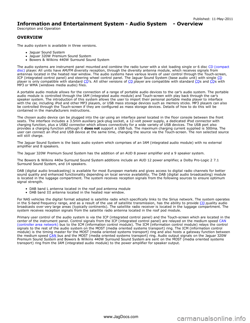
Primary user control of the audio system is via the ICP (integrated control panel) and the Touch-screen which are located in the
center of the instrument panel. Control signals from the ICP (integrated control panel) are relayed on the medium speed CAN
(controller area network) bus to the ICM (information control module). The ICM (information control module) relays the control
signals to the rest of the audio system on the MOST (media oriented systems transport) ring. The ICM (information control
module) is the timing master for the MOST (media oriented systems transport) ring and also hosts a gateway function between
the medium speed CAN bus and the MOST (media oriented systems transport) ring. Audio output signals on the Jaguar 320W Premium Sound System and Bowers & Wilkins 440W Surround Sound System are sent on the MOST (media oriented systems
transport) ring from the IAM (integrated audio module) to the power amplifier for speaker output. www.JagDocs.com
Page 1946 of 3039
Published: 11-May-2011
Information and Entertainment System - Audio System - System Operation
and Component Description
Description and Operation
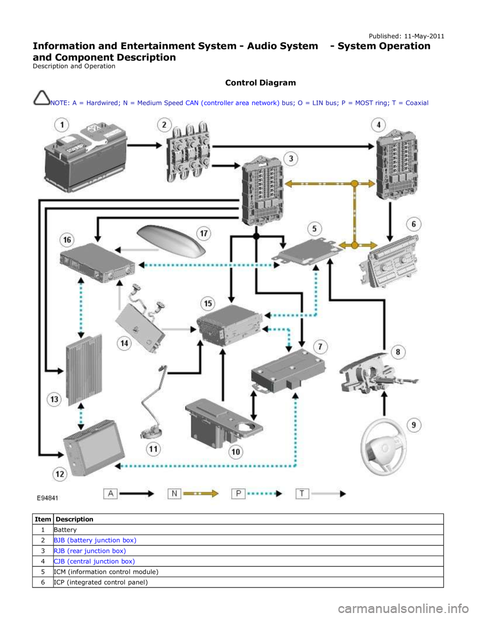
Control Diagram
NOTE: A = Hardwired; N = Medium Speed CAN (controller area network) bus; O = LIN bus; P = MOST ring; T = Coaxial
Item Description 1 Battery 2 BJB (battery junction box) 3 RJB (rear junction box) 4 CJB (central junction box) 5 ICM (information control module) 6 ICP (integrated control panel)