2010 JAGUAR XFR Can bus
[x] Cancel search: Can busPage 1948 of 3039
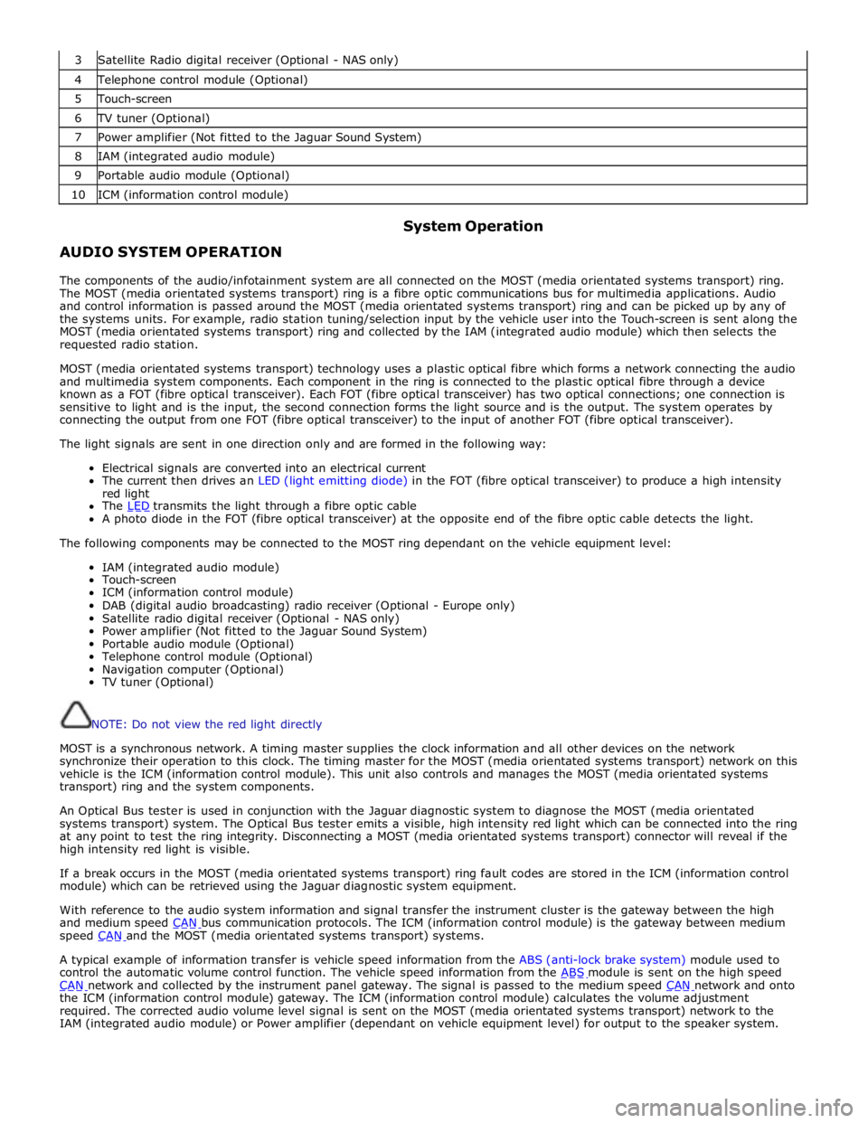
3 Satellite Radio digital receiver (Optional - NAS only) 4 Telephone control module (Optional) 5 Touch-screen 6 TV tuner (Optional) 7 Power amplifier (Not fitted to the Jaguar Sound System) 8 IAM (integrated audio module) 9 Portable audio module (Optional) 10 ICM (information control module)
AUDIO SYSTEM OPERATION System Operation
The components of the audio/infotainment system are all connected on the MOST (media orientated systems transport) ring.
The MOST (media orientated systems transport) ring is a fibre optic communications bus for multimedia applications. Audio
and control information is passed around the MOST (media orientated systems transport) ring and can be picked up by any of
the systems units. For example, radio station tuning/selection input by the vehicle user into the Touch-screen is sent along the
MOST (media orientated systems transport) ring and collected by the IAM (integrated audio module) which then selects the
requested radio station.
MOST (media orientated systems transport) technology uses a plastic optical fibre which forms a network connecting the audio
and multimedia system components. Each component in the ring is connected to the plastic optical fibre through a device
known as a FOT (fibre optical transceiver). Each FOT (fibre optical transceiver) has two optical connections; one connection is
sensitive to light and is the input, the second connection forms the light source and is the output. The system operates by
connecting the output from one FOT (fibre optical transceiver) to the input of another FOT (fibre optical transceiver).
The light signals are sent in one direction only and are formed in the following way:
Electrical signals are converted into an electrical current
The current then drives an LED (light emitting diode) in the FOT (fibre optical transceiver) to produce a high intensity
red light
The LED transmits the light through a fibre optic cable A photo diode in the FOT (fibre optical transceiver) at the opposite end of the fibre optic cable detects the light.
The following components may be connected to the MOST ring dependant on the vehicle equipment level:
IAM (integrated audio module)
Touch-screen
ICM (information control module)
DAB (digital audio broadcasting) radio receiver (Optional - Europe only)
Satellite radio digital receiver (Optional - NAS only)
Power amplifier (Not fitted to the Jaguar Sound System)
Portable audio module (Optional)
Telephone control module (Optional)
Navigation computer (Optional)
TV tuner (Optional)
NOTE: Do not view the red light directly
MOST is a synchronous network. A timing master supplies the clock information and all other devices on the network
synchronize their operation to this clock. The timing master for the MOST (media orientated systems transport) network on this
vehicle is the ICM (information control module). This unit also controls and manages the MOST (media orientated systems
transport) ring and the system components.
An Optical Bus tester is used in conjunction with the Jaguar diagnostic system to diagnose the MOST (media orientated
systems transport) system. The Optical Bus tester emits a visible, high intensity red light which can be connected into the ring
at any point to test the ring integrity. Disconnecting a MOST (media orientated systems transport) connector will reveal if the
high intensity red light is visible.
If a break occurs in the MOST (media orientated systems transport) ring fault codes are stored in the ICM (information control
module) which can be retrieved using the Jaguar diagnostic system equipment.
With reference to the audio system information and signal transfer the instrument cluster is the gateway between the high
and medium speed CAN bus communication protocols. The ICM (information control module) is the gateway between medium speed CAN and the MOST (media orientated systems transport) systems.
A typical example of information transfer is vehicle speed information from the ABS (anti-lock brake system) module used to
control the automatic volume control function. The vehicle speed information from the ABS module is sent on the high speed CAN network and collected by the instrument panel gateway. The signal is passed to the medium speed CAN network and onto the ICM (information control module) gateway. The ICM (information control module) calculates the volume adjustment
required. The corrected audio volume level signal is sent on the MOST (media orientated systems transport) network to the
IAM (integrated audio module) or Power amplifier (dependant on vehicle equipment level) for output to the speaker system.
Page 1956 of 3039
controlled through the device itself.
NOTE: The system will support devices with a storage capacity up to 256 GB which is approximately 65,000 audio tracks.
The wiring link harness between the portable audio module and interface panel consists of hardwired and digital connections
for data and signal exchange. The MOST carries the communication signals and information between the portable audio module
to the IAM and touch-screen. Audio output to the speaker system is controlled by the IAM or power amplifier depending on the
audio system specification.
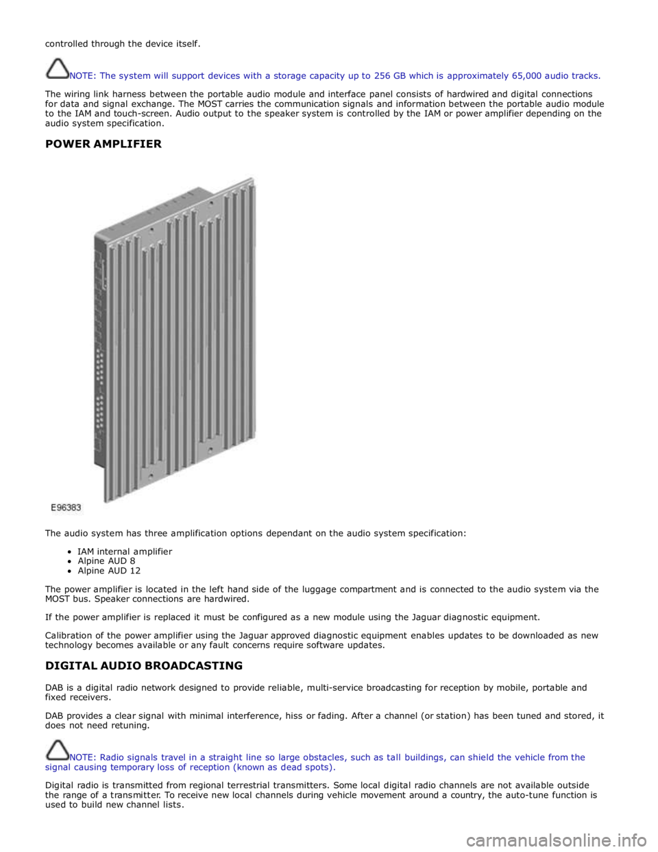
POWER AMPLIFIER
The audio system has three amplification options dependant on the audio system specification:
IAM internal amplifier
Alpine AUD 8
Alpine AUD 12
The power amplifier is located in the left hand side of the luggage compartment and is connected to the audio system via the
MOST bus. Speaker connections are hardwired.
If the power amplifier is replaced it must be configured as a new module using the Jaguar diagnostic equipment.
Calibration of the power amplifier using the Jaguar approved diagnostic equipment enables updates to be downloaded as new
technology becomes available or any fault concerns require software updates.
DIGITAL AUDIO BROADCASTING
DAB is a digital radio network designed to provide reliable, multi-service broadcasting for reception by mobile, portable and
fixed receivers.
DAB provides a clear signal with minimal interference, hiss or fading. After a channel (or station) has been tuned and stored, it
does not need retuning.
NOTE: Radio signals travel in a straight line so large obstacles, such as tall buildings, can shield the vehicle from the
signal causing temporary loss of reception (known as dead spots).
Digital radio is transmitted from regional terrestrial transmitters. Some local digital radio channels are not available outside
the range of a transmitter. To receive new local channels during vehicle movement around a country, the auto-tune function is
used to build new channel lists.
Page 1967 of 3039
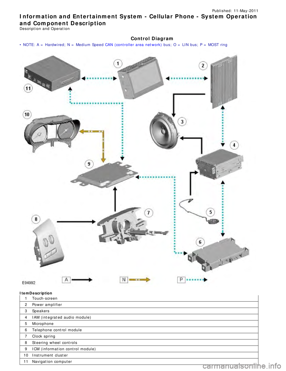
1
2
3
4
5
6
7
8
9
10
11Publi s hed: 11-May-2011
Information and Entertainment System - Cellular Phone - System Operation
and Component Description
Des cript ion and Operat ion
Control Diagram
• NOTE: A = Hardwi red; N = Medium Speed CAN (controller area net work) bus ; O = LIN bus ; P = MOST ringItemDescription
Touch-s creen
Power ampli fi er
Speakers
IAM (i nt egrat ed audi o module)
Microphone
Tel ephone cont rol module
Cl ock spring
St eering wheel cont rol s
ICM (i nformat ion control modul e)
Ins trument cl us t er
Navigat ion computer
Page 1973 of 3039

Published: 11-May-2011
Information and Entertainment System - Navigation System - Overview
Description and Operation
OVERVIEW
The navigation system provides audible and visual route guidance information to enable the driver to reach a desired
destination. The system allows the driver to choose the desired route using minor or major roads and will present 3 routes to
the driver based on user preferences. Directions to hospitals, museums, monuments and hotels are also available. The
navigation computer uses map information stored on a DVD (digital versatile disc) to determine the best route for the journey
and provide the driver with details of directions and approaching junctions.
The navigation system has various levels of user control through the Touch-screen and JaguarVoice system. System volume
adjustment can be made using the ICP (integrated control panel), Touch-screen and steering wheel controls.
There are 3 navigation system variants specific to various markets. On all systems the GPS (global positioning system) signal
is received by the GPS (global positioning system) antenna located in the roof pod antenna module.
The European navigation system includes the TMC (traffic messaging channel) function, which receives traffic information from
an FM antenna integrated into the heated rear window. On a pre-selected route the system will offer re-routing options
depending on traffic conditions.
The Japanese navigation system includes the VICS (vehicle information and communication systems) function. The VICS
(vehicle information and communication systems) supplies information to enable the navigation computer to re-route the
navigation guidance or to inform the vehicle driver of traffic conditions in the vehicles vicinity. Information is provided to the
system through an FM antenna integrated into the heated rear window and a VICS beacon located in the LH upper side of the
instrument panel.
The NAS (North American specification) variant does not include any additional traffic information systems.
The navigation system is primarily controlled from the Touch-screen which is located in the center of the instrument panel.
Control signals from the Touch-screen are sent on the MOST (media oriented systems transport) ring to the navigation
computer. The navigation computer uses a dedicated GVIF (gigabit video interface) bus to transmit video signals to the Touch-
screen.
Depending upon the audio system version fitted the navigation audio output signals are sent on the MOST (media oriented
systems transport) ring to the IAM (integrated audio module) or the power amplifier for speaker output.
Page 1974 of 3039
Published: 11-May-2011
Information and Entertainment System - Navigation System - System
Operation and Component Description
Description and Operation
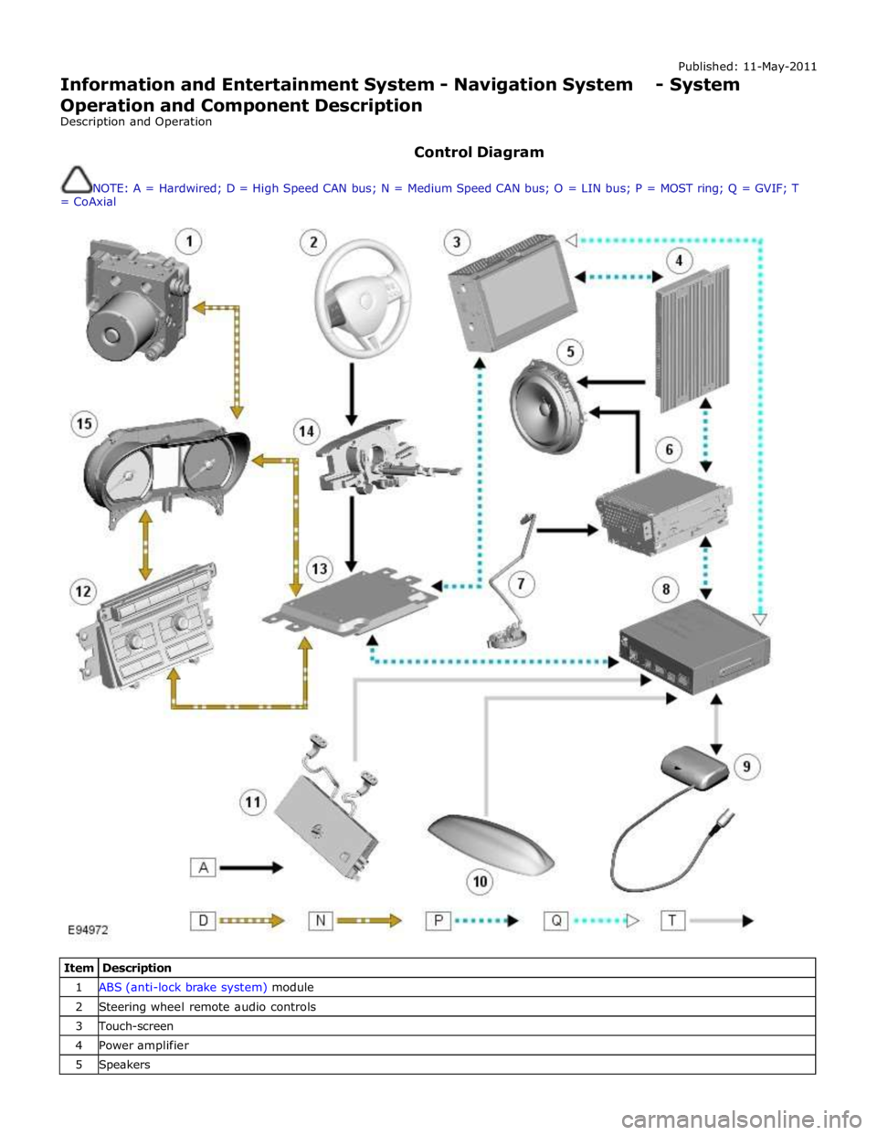
Control Diagram
NOTE: A = Hardwired; D = High Speed CAN bus; N = Medium Speed CAN bus; O = LIN bus; P = MOST ring; Q = GVIF; T
= CoAxial
Item Description 1 ABS (anti-lock brake system) module 2 Steering wheel remote audio controls 3 Touch-screen 4 Power amplifier 5 Speakers
Page 1985 of 3039
1
2
3
4
5
6
7
8
9
10Publi s hed: 11-May-2011
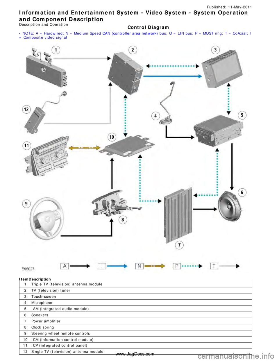
Information and Entertainment System - Video System - System Operation
and Component Description
Des cript ion and Operat ion
Control Diagram
• NOTE: A = Hardwi red; N = Medium Speed CAN (controller area net work) bus ; O = LIN bus ; P = MOST ring; T = CoAxial; I
= Compos it e video s i gnalItemDescription
Triple TV (televis i on) ant enna modul e
TV (t elevis ion) t uner
Touch-s creen
Microphone
IAM (i nt egrat ed audi o module)
Speakers
Power ampli fi er
Cl ock spring
St eering wheel remote controls
ICM (i nformat ion control modul e)11
12ICP (int egrated control panel)
Si ngl e TV (t el evi s ion) ant enna module
www.JagDocs.com
Page 1986 of 3039
System Operation
The Televis ion s ys tem has various l evels of us er cont rol t hrough the Touch-s creen, ICP (int egrated control panel) and
s teeri ng wheel control panel. The s ys tem includes nine analogue and nine di git al cha nnel pre-s et s . As wit h t he audio
s ys t em, the us er can s earch up or down and s tore by a l ong pres s of the s elect ed cha nnel but ton. The s ys t em offers a
choi ce of screen as pect rati os s imi lar t o a t ypi cal domes ti c receiver, givi ng opt ions bet ween the s t andard 4:3 format, wi de
s creen 16:9 format and zoom to fil l the screen.
To provide the s t rongest pos s ible si gnal t he Televis ion t uner recei ves s i gnal s from 4 ant enna s ources l ocat ed in the
heat ed rear wi ndow. Unl ike domes ti c s ys t ems t hi s s yst em gi ves a more progres s ive pict ure l oss if t he s ignal i s los t . The
s ignal los s is i ndicat ed t o t he user by a ‘los s of recepti on’ s creen mes s age.
The Televis ion s ys tem is primaril y cont rol led from the Touch-s creen and t he ICP (i nt egrat ed cont rol panel ) which are
located i n t he cent er of the i nst rument panel. Control s i gnals from t he Touch-screen di s pl ay are sent on t he MOST (media
ori ent ed s yst ems t rans port ) ri ng to the Televis i on tuner. The Televis i on tuner uses a dedi cat ed CVBS (compos it e video
s ignal) bus t o t ransmit video s i gnals to the Touch-s creen.
Control s i gnals from t he ICP (Integrat ed control panel) are rel ayed on the medi um s peed CAN bus t o t he ICM (i nformati on
cont rol module). The ICM (i nformati on cont rol module) rel ays the control s i gnal s to the Tel evi si on tuner on t he MOST
(medi a oriented s ys tems trans port ) ri ng. The ICM (i nformat ion control modul e) is t he t imi ng mas ter for the MOST (medi a
ori ent ed s yst ems t rans port ) ri ng and als o host s a gat eway functi on between t he medium s peed CAN bus and the MOST
(medi a oriented s ys tems trans port ) ri ng.
Dependi ng upon the audio sys tem vers ion fit ted the Televis i on tuner audi o output s ignals are s ent on the MOST (medi a
ori ent ed s yst ems t rans port ) ri ng to the IAM (int egrated audi o module) or the power a mpli fi er for s peaker out put.
Component Description
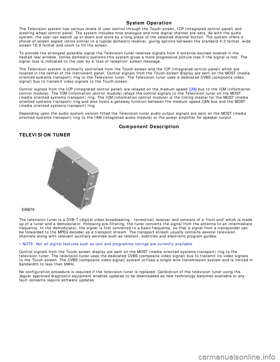
TELEVISION TUNERThe t el evi s ion t uner i s a DVB-T (di git al vi deo broadcas ti ng - terres trial ) receiver and cons is ts of a 'front end' whi ch is made
up of a t uner and a demodul at or. Foll owing pre-fi lt eri ng, t he t uner converts t he s ignal from t he antenna t o an i nt ermedi ate
frequency. In t he demodulator, the si gnal i s fi rs t convert ed t o a bas ic frequency, s o t hat a s ignal from a t rans ponder can
be forwarded t o t he MPEG decoder as a trans port s t ream. The t rans port s tream us ual ly contai ns several t el evi s ion
channels al ong wit h rel evant auxili ary s ervi ces s uch as t eletext , subt it les and electronic program guides .
• NOTE: Not all digi tal feat ures s uch as text and programme l is ti ngs are currentl y a vai lable.
Control s i gnals from t he Touch-screen di s pl ay are sent on t he MOST (media orient ed sys t ems transport) ring t o t he
t el evi s ion t uner. The tel evi si on tuner us es the dedicated CVBS (composi te vi deo s ignal) bus t o transmit i ts vi deo si gnal s
t o the Touch-s creen. The CVBS (composi te video s ignal) s yst em ut il izes a s i ngl e wire t rans mis s ion sys tem and is limit ed in
bandwi dth to l ess than 6MHz.
No confi gurati on procedure is required if t he tel evi si on t uner is replaced. Cal ibrat ion of t he t el evi s ion t uner us ing t he
Jaguar approved di agnos t ic equipment enabl es updat es to be downl oaded as new technol ogy becomes availabl e or any
faul t concerns require s oft ware updat es .
Page 1989 of 3039
1
2
3
4
5
6
1
2
3
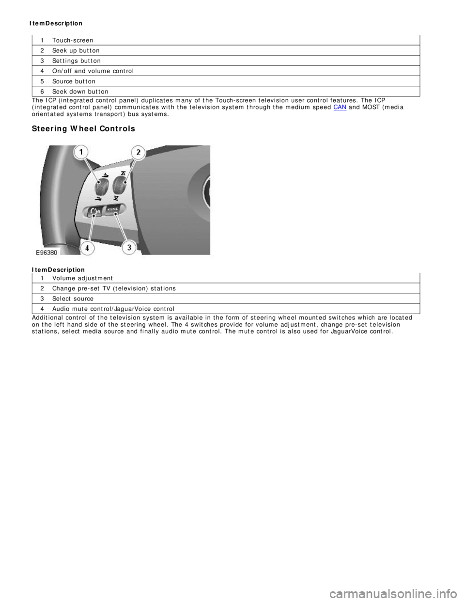
4Touch-s creen
Seek up but ton
Set ti ngs but ton
O n/off and volume cont rol
Source but ton
Seek down but ton
The ICP (i ntegrat ed cont rol panel ) dupl icates many of t he Touch-s creen tel evi si on user control features . The ICP
(integrat ed cont rol panel) communicates wi th the televis i on sys t em t hrough the medium speed CAN and MOST (medi a
ori ent ated sys tems trans port ) bus s ys t ems .
Steering Wheel ControlsItemDescription
Vol ume adjus tment
Change pre-s et TV (t elevis ion) s tat ions
Sel ect s ource
Audio mute cont rol/JaguarVoi ce cont rol
Addit ional control of t he t elevis ion s ys tem is avail abl e in the form of s teeri ng whe el mount ed s wit ches whi ch are l ocat ed
on t he left hand si de of the s t eering wheel . The 4 s wit ches provi de for volume adjus t ment, change pre-s et t elevis ion
s tat ions , sel ect media s ource and fi nal ly audio mute cont rol. The mut e control i s al s o us ed for JaguarVoice cont rol . ItemDescription